IS9100
—
MDC
9ISEO
L1
N
24
25
26
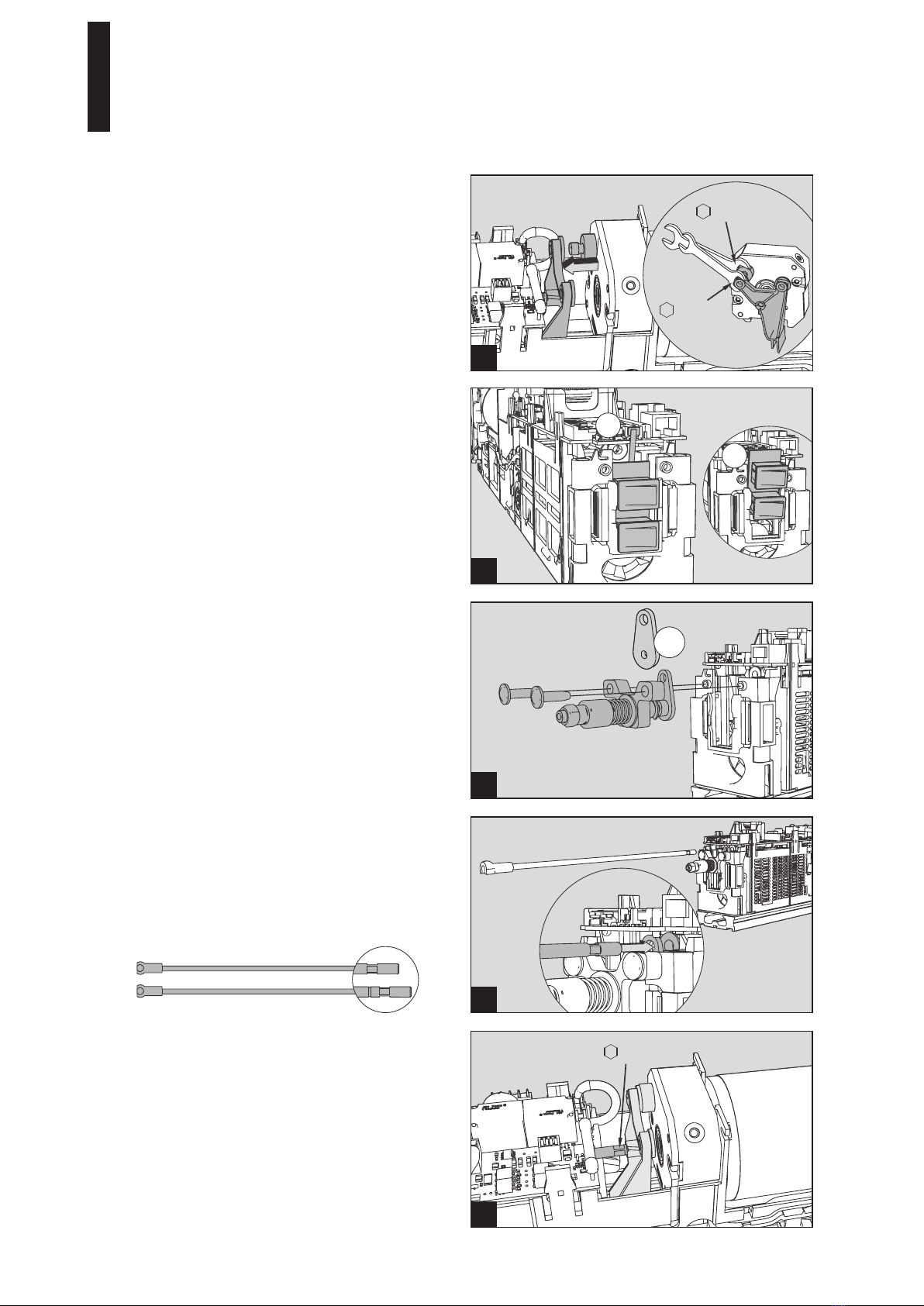
4. Installation of operators
Fix the mounting plates for both operators.
Please consider the mounting instructions for the IS9100
(pages 8 to 12 & page 14).
Don’t forget to put supplied holding pins.
Connect the 230 V supply at one of the mounting plates.
Work on electrical equipment may only be performed
by properly qualified staff (electricians).
Connect earthing (grounding) cable.
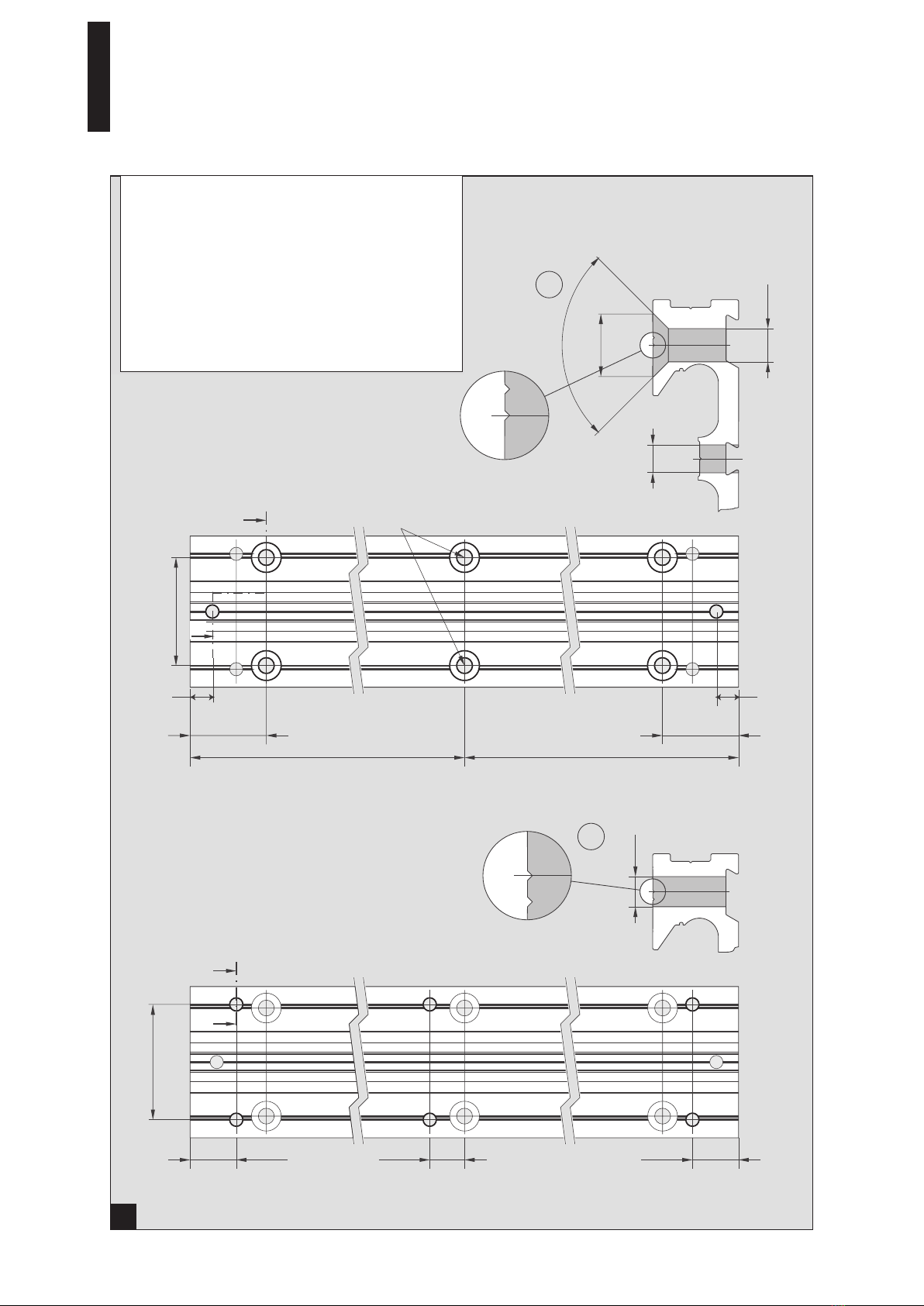
Lay the mains cable for the second operator inside the
groove of the mounting plates ➀.
Also lay the cable for the program switch and, if required,
further cables inside the provided groove ②.
Cables are provided with the kit ACE.
Small plastic sheet will help you to hold wires into grooves.
Mount both operators.
Then mount the standard arm or the slide channel.
Please consider the mounting instructions for the IS9100
accompanying the operators.
27
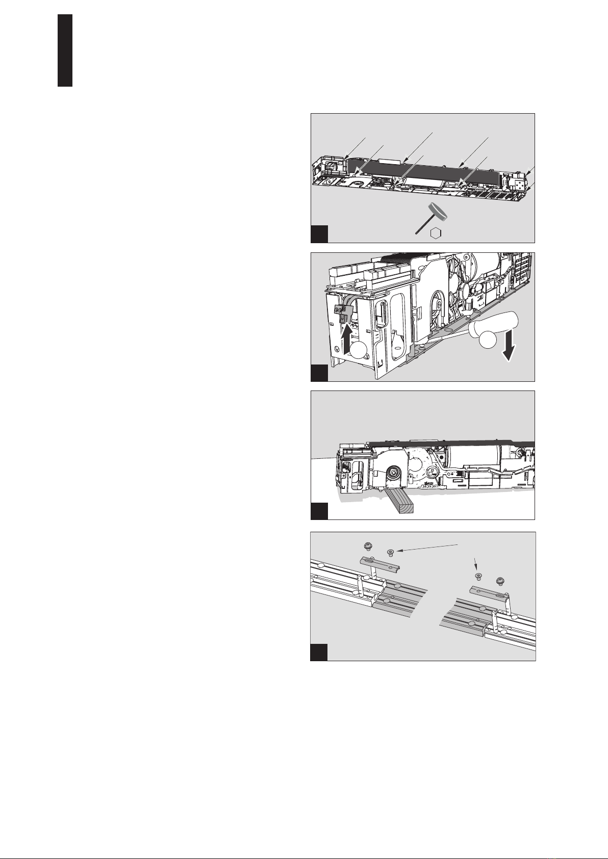
Preparation of brackets
Break out the plastic parts located in the middle of both
brackets by turning them upwards, then use as air deflector
at the bottom of the bracket.
supply
power
cable
internal program
switch cables
with or without
"exit only" function
connection
wires for DAS
version
(NFS 61937)
FRANCE