ECO Schulte SR BG III User manual

1/15
ECO Schulte GmbH & Co. KG
Iserlohner Landstraße 89
D-58706 Menden
3-5 21 13 5
19
0432-CPR-00099-06 EN 1158:1997/A1:2002/AC:2006
Leistungserklärung nach Verordnung (EU) Nr. 305/2011 finden Sie unter http://www.eco-schulte.de/leistungserklaerungen
Declaration of performance according to Regulation (EU) No 305/2011 see http://www.eco-schulte.de/declarationofperformance
Déclaration des performances conformément au règlement (UE) N° 305/2011 voir http://www.eco-schulte.de/declarationdesperformances
Only original parts have to be used. The assembly has to be made by a qualified person according to the mounting instruction. In case of
non-respect the guarantee is invalid. This instruction is to be handed over to the operator by the fitter after assembly!
Impérativement utiliser la notice de montage fournie par le fabricant. La mise en œuvre et le montage doivent être exécutés par du person-
nel qualifié. Le non respect de ces règles annule catégoriquement tout droit de garantie. Cette instruction est à remettre par le poseur
à l’exploitant après montage.
Für die Montage dürfen ausschließlich Originalteile des Herstellers verwendet werden. Die Montagearbeiten müssen gemäß Anleitung von
einer qualifizierten Person durchgeführt werden. Bei Nichtbeachtung entfällt jeglicher Garantieanspruch. Diese Anleitung ist vom Monteur
nach der Montage an den Betreiber weiterzugeben!
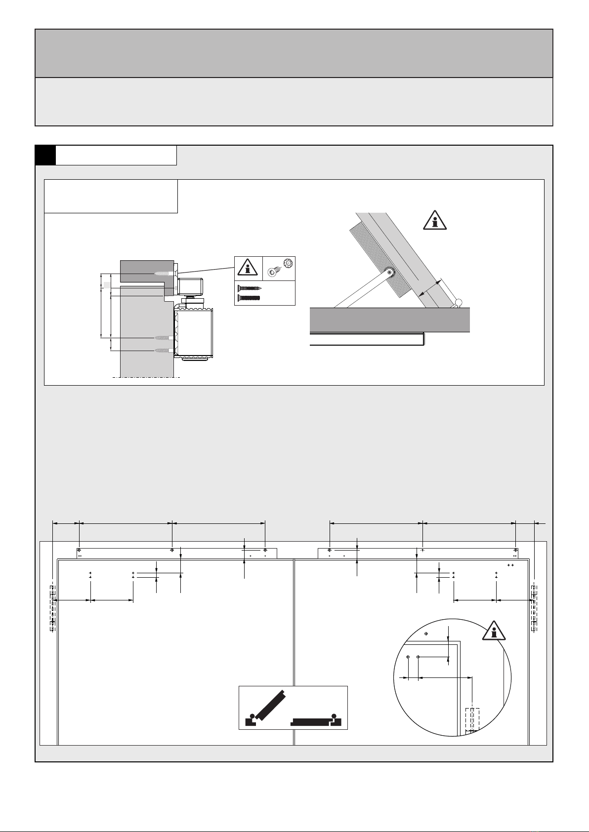
Für die Montage sowie die Ventileinstellungen des Türschließers
beachten Sie bitte die dem Türschließer beiliegende separate
Montageanleitung.
Please refer to the enclosed assembly instruction of the doorcloser
for mounting as well as adjusting the valves of the doorcloser.
Pour le montage et le réglage des ferme-portes, merci d'utiliser la
notice de pose incluse séparément.
!
Bei Vollpanikfunktion ist eine Mitnehmerklappe
MK Basis 2 zu montieren.
Nicht im Lieferumfang enthalten!
With full panic function, a panic flap MK Basis 2
must be installed.
Not included in the delivery!
En cas de montage d'Anti-paniques sur les deux
vantaux, il faut utiliser l'entraineur MK Basis 2.
(N'est pas compris dans la livraison, à commander
séparément)
max.
3,5mm
GS
DIN links - spiegelbildlich
DIN left - mirror image
DIN gauche - inverser l´illustration
Montageanleitung / Assembly instruction / Notice de montage
ECO SR BG III
ECO SR BG III
ECO SR BG III
(DIN rechts / DIN links spiegelbildlich)
(DIN right / DIN left mirror image)
(DIN droite / DIN gauche inverser l‘illustration)
© Änderungen vorbehalten / ECO SR BG III / MTS00754 / 5030056241 / Index: a

2/15
1a
X
X = 60-95mm
Direktmontage (ohne Unterprofil)
Direct mounting (without underprofile)
Montage direct (sans sous profil)
106 65636
11
11
142 160
16
53
53
160 142
16
698
G S
A
16 64
53
24
77
15
A
Montageanleitung / Assembly instruction / Notice de montage
ECO SR BG III
ECO SR BG III
ECO SR BG III
(DIN rechts / DIN links spiegelbildlich)
(DIN right / DIN left mirror image)
(DIN droite / DIN gauche inverser l‘illustration)
3/15
X
X = 60-95mm
Montage mit Adaptionsprofil
Mounting with adaptor plate
Montage avec profil d’adaptation
99 349 349 65349349
33
33
142 160
16
53
53
160 142
16
A
16
64
53
22
33
G S
24
77
15
A
1b (optional, optional, optionnelle)
Montageanleitung / Assembly instruction / Notice de montage
ECO SR BG III
ECO SR BG III
ECO SR BG III
(DIN rechts / DIN links spiegelbildlich)
(DIN right / DIN left mirror image)
(DIN droite / DIN gauche inverser l‘illustration)
M5x20
5x30

4/15
Montage mit Sturzfutterwinkel
Mounting with under-lintle angle
Montage sous linteau avec équerre X = 65-95mm
X
56,5
<
16
83
142 160
16
83
160 142
A
96,5
185 300 185 185300185
16
23
16
23
130,5
16 83
716
G S
54
77
15
A
1c (optional, optional, optionnelle)
Montageanleitung / Assembly instruction / Notice de montage
ECO SR BG III
ECO SR BG III
ECO SR BG III
(DIN rechts / DIN links spiegelbildlich)
(DIN right / DIN left mirror image)
(DIN droite / DIN gauche inverser l‘illustration)
5/15
2
3
4
!
!
!
!
Montageanleitung / Assembly instruction / Notice de montage
ECO SR BG III
ECO SR BG III
ECO SR BG III
(DIN rechts / DIN links spiegelbildlich)
(DIN right / DIN left mirror image)
(DIN droite / DIN gauche inverser l‘illustration)
6/15
5a
5b (optional, optional, optionnelle)
5c (optional, optional, optionnelle)
Direktmontage (ohne Unterprofil)
Direct mounting (without underprofile)
Montage direct (sans sous profil)
M5x20
5x30
M5x20
5x30
M5x20
5x30
M5x20
5x30
M5x20
5x30
M5x20
5x30
3
22
3
2
M5x20
5x30
1
M5x20
5x30
1
M5x20
5x30
1
Montage mit Adaptionsprofil 40mm
Mounting with adaptor plate 40mm
Montage avec profil d‘adaption 40mm
Montage mit Sturzfutterwinkel 30mm
Mounting with under-lintle angle 30mm
Montage 30mm sous linteau avec équerre
Montageanleitung / Assembly instruction / Notice de montage
ECO SR BG III
ECO SR BG III
ECO SR BG III
(DIN rechts / DIN links spiegelbildlich)
(DIN right / DIN left mirror image)
(DIN droite / DIN gauche inverser l‘illustration)

7/15
6b (optional, optional, optionnelle)
6a
M5x40
5x60
M5x40
5x60
M5x20
5x30
M5x12
M5x35
M5x35
M5x35
M5x35
6c (optional, optional, optionnelle)
Direktmontage (ohne Unterprofil)
Direct mounting (without underprofile)
Montage direct (sans sous profil)
Montage mit Adaptionsprofil 40mm
Mounting with adaptor plate 40mm
Montage avec profil d‘adaption 40mm
Montage mit Sturzfutterwinkel 30mm
Mounting with under-lintle angle 30mm
Montage 30mm sous linteau avec équerre
M5x12
Montageanleitung / Assembly instruction / Notice de montage
ECO SR BG III
ECO SR BG III
ECO SR BG III
(DIN rechts / DIN links spiegelbildlich)
(DIN right / DIN left mirror image)
(DIN droite / DIN gauche inverser l‘illustration)

8/15
Für die Montage des Türschließers beachten Sie bitte die
dem Türschließer beiliegende separate Montageanleitung.
Refer to the enclosed assemby instruction of the doorcloser
for mounting of the doorcloser.
Pour le montage des ferme-portes, merci d'utiliser la notice
de pose incluse séparément.
7
9
8
2
1
2
12
2
5Nm
2
Öffnen der Ventile wie in der beiliegenden
Montageanleitung des Türschließers beschrieben.
Open the valves as described in the enclosed assembly
instruction of the doorcloser.
Ouvrir les valves de réglages comme indiqué dans la
notice de pose incluse séparément.
SW 2,5
SG/CS/VF
2
1
Montageanleitung / Assembly instruction / Notice de montage
ECO SR BG III
ECO SR BG III
ECO SR BG III
(DIN rechts / DIN links spiegelbildlich)
(DIN right / DIN left mirror image)
(DIN droite / DIN gauche inverser l‘illustration)

9/15
2
max.
1
max.
10
12
Ymax 8mm
3mm
A
5mm
B
Xmax 2mm
+
max. 1
2.1
2.2
11
1
Montageanleitung / Assembly instruction / Notice de montage
ECO SR BG III
ECO SR BG III
ECO SR BG III
(DIN rechts / DIN links spiegelbildlich)
(DIN right / DIN left mirror image)
(DIN droite / DIN gauche inverser l‘illustration)
a
b
2
Den Standflügel öffnen . Der Schiebeblock wird durch den Gleitschuh verschoben. Am Umkehrpunkt,
an dem der Gleitschuh anfängt wieder in die Gegenrichtung zu fahren, wird der Schiebeblock mit
den beiden Schrauben fixiert.
Open the inactive leaf . The shifting block will be moved by the sliding block . When the sliding block
reaches the reversal point where it will start moving into the opposite direction, the shifting block must be
fixed with the pair of set screws .
Ouvrez le vantail secondaire . Le bloc coulissant est déplacé par le patin . Au point de retournement,
où le patin commence à revenir dans le sens opposé, le bloc coulissant doit être fixé à l'aide des deux
vis .
a a
a
a
a
a
b
b
b
b
b
b
1
1
1
2
2
2

10/15
13
Die Einstellungen des Türschließers sind der dem
Türschließer beiliegenden Montageanleitung zu
entnehmen.
The adjustments of the doorcloser can be taken
from the enclosed assembly instruction of the
doorcloser.
Pour le réglage des ferme-portes, merci d'utiliser
la notice de pose incluse séparément.
nicht bei allen Türschließertypen verfügbar
not available on all types of door closers
Pas disponible sur tous les types de ferme-portes
*
Einstellungen Türschließer
Adjustments of the door closer
Reglages du ferme - portes
SK
ES
ÖD
SG
Endschlag
Öffnungs-
dämpfung
Schließkraft CF
Abkürzungen Abbreviations Abréviations
Closing speed
LS
BC
CS
Latching speed
Back check
Closing force
Vitesse de
fermeture
FF
CF
FO
VF
Coup final
Frein á
l’ouverture
Force de
fermeture
Schließ-
geschwindigkeit
SV Schließ-
verzögerung DA Delay action TF Temporisation à
la fermeture
*
*
15
Ls + 214 mm
2
Ls
1
Ls
14
ca.105° ca.105°
S
GTürstopper setzen
Place door stopper
Placer butoir de porte
Montageanleitung / Assembly instruction / Notice de montage
ECO SR BG III
ECO SR BG III
ECO SR BG III
(DIN rechts / DIN links spiegelbildlich)
(DIN right / DIN left mirror image)
(DIN droite / DIN gauche inverser l‘illustration)

11/15
16
18
Funktionsprüfung SR
Functional test SR
Test fonctionnel SR
17
LA
1
LA - 6 mm
2
LA
3
1
90°
2
SW2,5
2x
4
SW2,5
2x
Montageanleitung / Assembly instruction / Notice de montage
ECO SR BG III
ECO SR BG III
ECO SR BG III
(DIN rechts / DIN links spiegelbildlich)
(DIN right / DIN left mirror image)
(DIN droite / DIN gauche inverser l‘illustration)

12/15
19
31
1
2
2
3
Montageanleitung / Assembly instruction / Notice de montage
ECO SR BG III
ECO SR BG III
ECO SR BG III
(DIN rechts / DIN links spiegelbildlich)
(DIN right / DIN left mirror image)
(DIN droite / DIN gauche inverser l‘illustration)
13/15
Montageanleitung / Assembly instruction / Notice de montage
ECO SR BG III
ECO SR BG III
ECO SR BG III
(DIN rechts / DIN links spiegelbildlich)
(DIN right / DIN left mirror image)
(DIN droite / DIN gauche inverser l‘illustration)
Im Folgenden wird die Montage für Gangflügel DIN rechts gezeigt. Bei Gangflügel DIN links bitte entsprechend spiegel-
bildlich vorgehen.
14
Abhängig von den baulichen Gegebenheiten und der vorhandenen Türstärke beträgt der maximale Öffnungswinkel
der Türen ca. 105°. Um Beschädigungen der Türen bzw. der Türschließer zu vermeiden, ist am maximalen Öffnungs-
winkel ein Türstopper zu setzen! (Gang- und Standflügel)
5b
6a-c
1
9
10
12
15
16
2
17
18
12
3
4
12
5a
5c
12
3
1
2
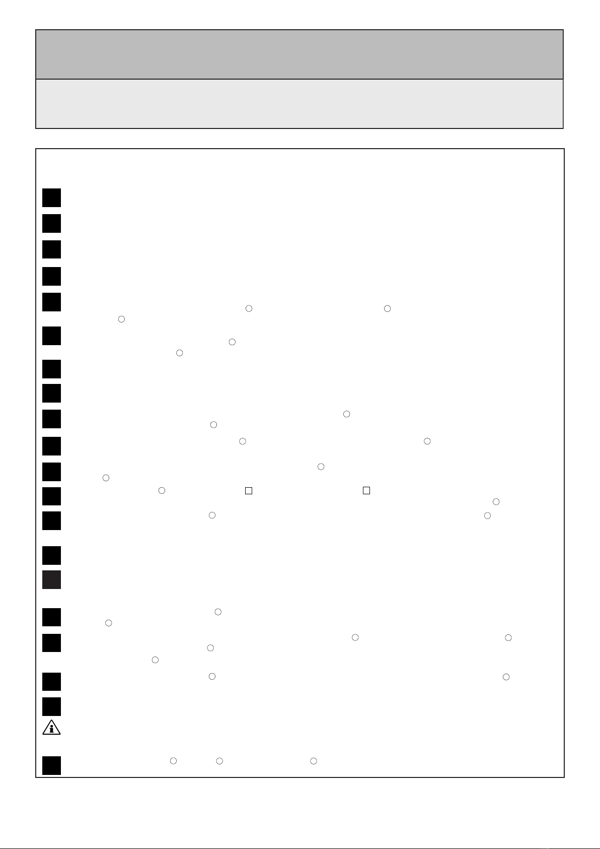
Montageplatten (Türschließer) anschrauben.
Adaptionsprofile (optional) bei Bedarf kürzen und anschließend anschrauben . Montageplatten (Türschließer)
anschrauben .
Montage mit Adaptionsprofil
Direktmontage
Montage mit Sturzfutterwinkel
Den Auslöseblock auf Anschlag in Richtung Türmitte schieben . Den Schiebeblock auf Anschlag gegen den Gleitschuh
schieben .
Sturzfutterwinkel (optional) anschrauben , Gangflügelprofil gegebenenfalls bei Überlappung kürzen. Montageplatten
(Türschließer) anschrauben .
Gangflügelgleitschiene und Standflügelgleitschiene montieren.
Maß Ls gemäß Darstellung ermitteln . Verbindungsstange auf entsprechendes Maß Ls+214mm ablängen und
entgraten .
Abdeckprofil montieren.
Maß LA gemäß Darstellung ermitteln . Abdeckprofil auf entsprechendes Maß LA - 6mm ablängen und entgraten .
Funktionsprüfung SR
Beide Türen ca. 60° öffnen, Gangflügel muss geöffnet bleiben. Standflügel schließt. Gangflügel darf erst ab einem Schließ-
winkel des Standflügels von ca. 30° schließen.
Verbindungsmuffen wie dargestellt auf die Verbindungsstange schieben . Verbindungsstange um 90° drehen und
zwischen die Stangenenden führen . Die Verbindungsmuffen über die Stangenenden auf Anschlag schieben und Maden-
schrauben festziehen . Wichtig: Die Schrauben der Verbindungsmuffen müssen nach unten zeigen.
Bohrschablone anlegen und je nach Anbauvariante Bohrlochgruppe wählen und Löcher bohren.
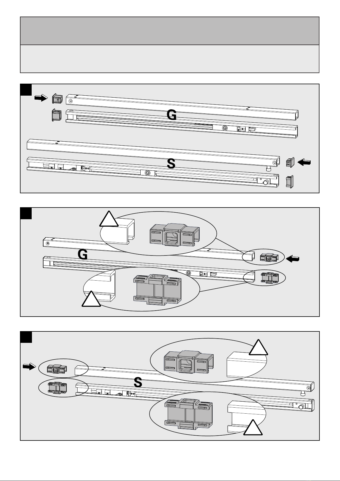
2Endkappen in die Gleitschienen des Gangflügels (G) und des Standflügels (S) einsetzen.
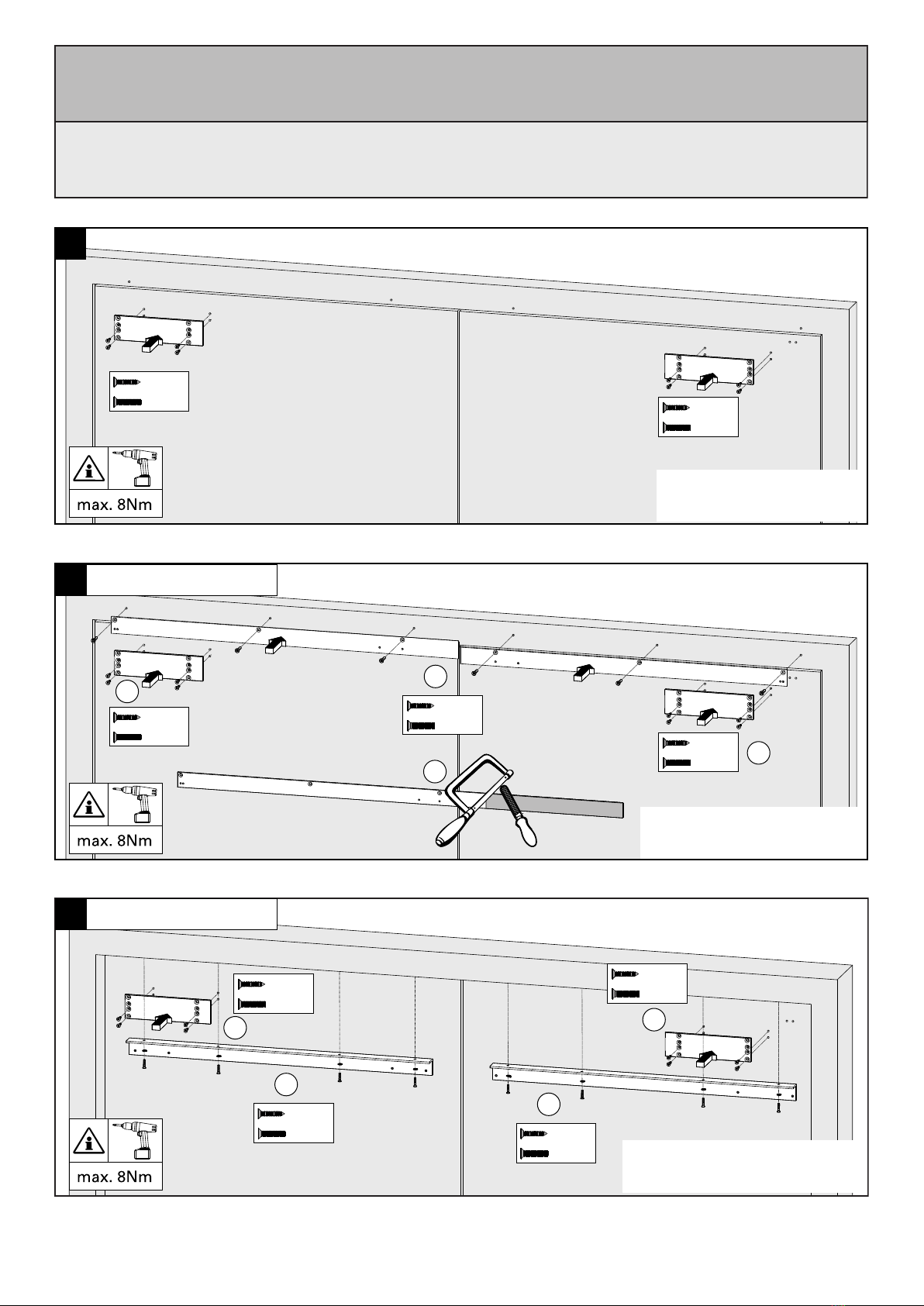
3+4 Mittelstück in die Gangflügelschiene (G) bzw. in die Standflügelschiene (S) einsetzen. Es ist darauf zu achten,
dass die Nasen am Mittelstück nach vorne und nach unten zeigen!
1a-c Bohrbild entsprechend der Zeichnung bohren.
7
81
1
2
Türschließer montieren.
Nach Schließen der Schließgeschwindigkeitsventile die Türen öffnen und den Hebelarm zur Gleitschiene führen.
Hebelarm mit Gleitschuh verbinden .
1
2
2
Auslösebock auf Anschlag schieben . Auslösewinkel auf Anschlag an die Rolle schieben und montieren .
Wichtig: Der maximale Zargenüberstand beträgt 2mm, darüber sind die Distanzplatten A oder B zu verwenden.
Der maximale Zargenüberstand mit Platten beträgt 8mm, darüber bitte anfragen.
12
13 Türschließer nach separater Anleitung einstellen.
Kunststoff-Clips einsetzen . U-Cover und Ritzelabdeckung am Türschließer aufklippen.
123
19
11 Den Standflügel öffnen . Der Schiebeblock wird durch den Gleitschuh verschoben. Am Umkehrpunkt, an dem der
Gleitschuh anfängt wieder in die Gegenrichtung zu fahren, wird der Schiebeblock mit den beiden Schrauben fixiert.
a
b
12
Öffnen der Schließgeschwindigkeitsventile und die Türen folgerichtig schließen lassen .

14/15
Montageanleitung / Assembly instruction / Notice de montage
ECO SR BG III
ECO SR BG III
ECO SR BG III
(DIN rechts / DIN links spiegelbildlich)
(DIN right / DIN left mirror image)
(DIN droite / DIN gauche inverser l‘illustration)
Assembly for active leaves DIN right is described below. For active leaves DIN left, please proceed accordingly.
14
5b
6a-c
9
10
12
15
16
17
18
5a
5c
2
3+4
1a-c
7
8
13
19
Attach the drilling template and choose corresponding drill holes depending on mounting situation. Drill the holes.
Drill the hole pattern according to the drawing.
Insert the end caps into the active leaf slide rail (G) and into the passive leaf slide rail (S).
Insert the middle pieces into the active leaf slide rail (G) and into the passive leaf slide rail (S). The lugs on the middle pieces
have to point forwards and downwards!
13
2
1
2
Mounting with under-lintle angle
Direct mounting
Mounting with adaptor plate
Screw on the under-lintle angle (optional), shorten the active leaf profile if necessary. Screw on the door closer
mounting plates .
Screw on the adaptor plates (optional), shorten if necessary .Screw on the door closer mounting plates .
Screw on the door closer mounting plates.
Mount the active leaf slide rail and the passive leaf slide rail.
Fit the door closer.
The maximum opening angle of the door leaves is approx. 105°, depending on the constructional condition and the
door thickness. In order to avoid damages on doors and / or door closers, please set a door stopper at the
maximum opening angle (active and passive leaf).
1
2
Determine dimension Ls in line with drawing . Cut connecting rod to length in line with said dimension Ls + 214 mm
and trim .
12
34
Push coupling sleeves as depicted onto the connecting rod . Turn the connecting rod by 90° .Push connecting rod between
the rod ends . Push the coupling sleeves over the rod ends and tighten grub screws . Attention: the screws of the coupling
sleeves have to point downwards.
2
Determine dimension LA acc. to drawing . Cut the cover profile to dimension LA - 6mm and deburr .
1
Attach the cover profile.
Functionality test SR
Open both doors approx. 60°, the active leaf has to remain open. The Passive leaf closes. The active leaf is only allowed to
close if the passive leaf reaches a closing angle of approx. 30°.
123
Attach the nylon clips . Clip on U-Cover and pinion cover .
Adjust the doorcloser as stated in the separate mounting instruction.
Move the triggering block until stop . Mount triggering angle at stop on the roll . Important: maximum projection length of
the door frame is 2mm, otherwise use distance plates A or B. The maximum projection length of the door frame with distance
plates is 8mm, all other lengths on request.
12
Open the valve for the closing speed and close the doors in the correct order .
1
1
1
2
2
2
Push the triggering block to its stop in direction of the door centre. Push the follower against the sliding block.
11
Open the inactive leaf . The shifting block will be moved by the sliding block . When the sliding block reaches the
reversal point where it will start moving into the opposite direction, the sliding block must be fixed with the pair of set screws .
1
2
a
b
After closing the valve for the closing speed,open the doors . Connect the arm to the sliding block .
15/15
Montageanleitung / Assembly instruction / Notice de montage
ECO SR BG III
ECO SR BG III
ECO SR BG III
(DIN rechts / DIN links spiegelbildlich)
(DIN right / DIN left mirror image)
(DIN droite / DIN gauche inverser l‘illustration)
Ci-dessous le montage pour vantail principal droite. Pour le montage à gauche veuillez procéder en conséquence.
1
Ci-dessous le montage pour vantail principal droite. Pour le montage à gauche veuillez procéder en conséquence.
14
5b
6a-c
1
9
10
12
15
16
17
18
12
34
12
5a
5c
123
1
2
Montage sous linteau avec équerre
Faites glisser le bloc de déclenchement jusqu'en butée en direction du centre de la porte . Faites glisser le bloc
coulissant contre le patin .
Fixer l'équerre (optionel) , Si besoin, raccourcir le profil du vantail principal en cas de chevauchement. Fixer la plaque de
montage du ferme-porte .
2
3+4
1a-c
7
81
2
1
2
2
1
1
2
13
19
Positionner le gabarit de perçage et selon le cas de configuration, choisir les trous adaptés puis perçer.
Percer le motif de trous après le dessin.
Fixer les embouts dans la glissière de vantail secondaire (S) et vantail principal (G).
Insérer la pièce centrale soit dans la glissière du vantail secondaire (S) soit dans la glissière du vantail principal (G).
Prêter attention que le "nez" de la pièce centrale soit face à vous et tournée vers le bas.
Montage direct
Fixer la plaque de montage du ferme-porte.
Montage avec profil d’adaptation
Fixer le ferme-portes.
Fixer la glissière du vantail principal et du vantail secondaire.
Selon les informations fournies et selon l’épaisseur de la porte, l’angle d’ouverture des vantaux est de 105°.
Il est conseillé de fixer un butoir de porte pour chaque vantail.
Ajuster le ferme-porte, merci d‘utiliser la notice de pose incluse séparément.
2
Prendre la mesure Ls comme indiqué . Recouper et ébavurer la tige à la dimension Ls +214 mm .
Positionner comme indiqué les manchons de raccordement sur la tige . Tourner la tige de 90° , positionner et fixer les
manchons à l’aide des vis 6 pans creuses . (les vis doivent être dirigées vers le bas).
Prendre la mesure LA comme indiqué . Recouper et ébavurer le profil de recouvrement à la dimension LA -6mm .
Fixer le profil de recouvrement.
Test du sélecteur.
Ouvrir les deux vantaux à 60°, le vantail principal doit se maintenir en position ouverte. Le vantail secondaire doit se fermer.
Le vantail principal doit se fermer à partir d’un angle de fermeture du vantail secondaire à partir de 30°.
23
Positionner les clips plastique . Clipser le capot U du ferme-portes ainsi que le cache de l’axe .
Faire glisser le patin à rouleau de la glissière en butée . Monter l’équerre jusqu’au rouleau .
Important: Recouvrement maximum 2mm, si plus utiliser les cales A (3mm) ou B (5mm). Au-delà de 8mm de recouvrement,
nous consulter.
Serrer la vis de réglagle de la vitesse de fermeture et ouvrir les deux vantaux. Fixer le bras de levier au patin de la
glissière .
Fixer le profile d‘adaption (en option); recouper si necessaire . Fixer la plaque de montage du ferme-porte .
11 Ouvrez le vantail secondaire . Le bloc coulissant est déplacé par le patin . Au point de retournement, où le patin
commence à revenir dans le sens opposé, le bloc coulissant doit être fixé à l'aide des deux vis .
a
b
12
Desserrer la vis de réglagle de la vitesse de fermeture et ferme les deux vantaux .
Other ECO Schulte Door Opening System manuals

ECO Schulte
ECO Schulte EF BG User manual

ECO Schulte
ECO Schulte FSA ECO SR-EFR User manual

ECO Schulte
ECO Schulte ETS 42 User manual

ECO Schulte
ECO Schulte ECO SR-EF User manual

ECO Schulte
ECO Schulte FSA ECO SR-EFR User manual

ECO Schulte
ECO Schulte ECO EF User manual

ECO Schulte
ECO Schulte FH842 User manual

ECO Schulte
ECO Schulte SR BGX User manual


