Helmer i.series User manual

HELMER SCIENTIFIC
14400 Bergen Boulevard
Noblesville, IN 46060 USA
PH +1.317.773.9073
FAX +1.317.773.9082
USA and Canada 800.743.5637
0086
ISO 13485:2003 CERTIFIED
Undercounter Refrigerator Operation Manual
i.Series®and Horizon Series™
Model Group i.Series Horizon Series
Blood Bank iB105 (Version A) HB105 (Version A)
Laboratory/Pharmacy iLR105 (Version A) HLR105 (Version A)
360116-1/D

360116-1/D i
Document History
Revision Date CO Supersession Revision Description
D16 JAN 2014* 8580 Supersedes A,
B, C Revised layout for ease of navigation and locating information.
* Date submitted for Change Order review. Actual release date may vary.

360116-1/D ii
Contents
Section I: General Information ........................................4
1 About this Manual .......................................................... 4
1.1 Intended Audience. . . . . . . . . . . . . . . . . . . . . . . . . . . . . . . . . . . . . . . . . . . . . . . . . . . . . . . . . . . . . . . . . . . . . . 4
1.2 Model References ......................................................................4
1.3 Copyright and Trademark ................................................................4
2 Safety .................................................................... 4
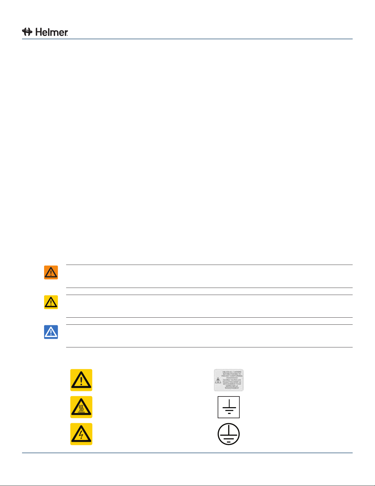
2.1 SafetyDenitions ......................................................................4
2.2 Product Labels ........................................................................4
2.3 Avoiding Injury.........................................................................5
3 General Recommendations. . . . . . . . . . . . . . . . . . . . . . . . . . . . . . . . . . . . . . . . . . . . . . . . . . . 5
3.1 Intended Use..........................................................................5
3.2 General Use ..........................................................................5
3.3 Initial Loading .........................................................................5
4 Specications.............................................................. 6
4.1 Stacked Undercounter Units ..............................................................7
5 Compliance................................................................ 8
5.1 Regulatory Compliance..................................................................8
5.2 WEEE Compliance .....................................................................8
6 Installation ................................................................ 8
6.1 Location Requirements ..................................................................8
6.2 Install AC Power Cord ...................................................................8
6.3 Placement ............................................................................9
6.4 Temperature Probes ....................................................................9
6.5 Temperature Chart Recorder. . . . . . . . . . . . . . . . . . . . . . . . . . . . . . . . . . . . . . . . . . . . . . . . . . . . . . . . . . . . . . 9
6.5.1 Install and Change Chart Paper ....................................................10
7 Maintenance Schedule ..................................................... 11
Section II: i.Series®Models..........................................12
8 Operation ................................................................ 12
8.1 Initial Start Up ........................................................................12
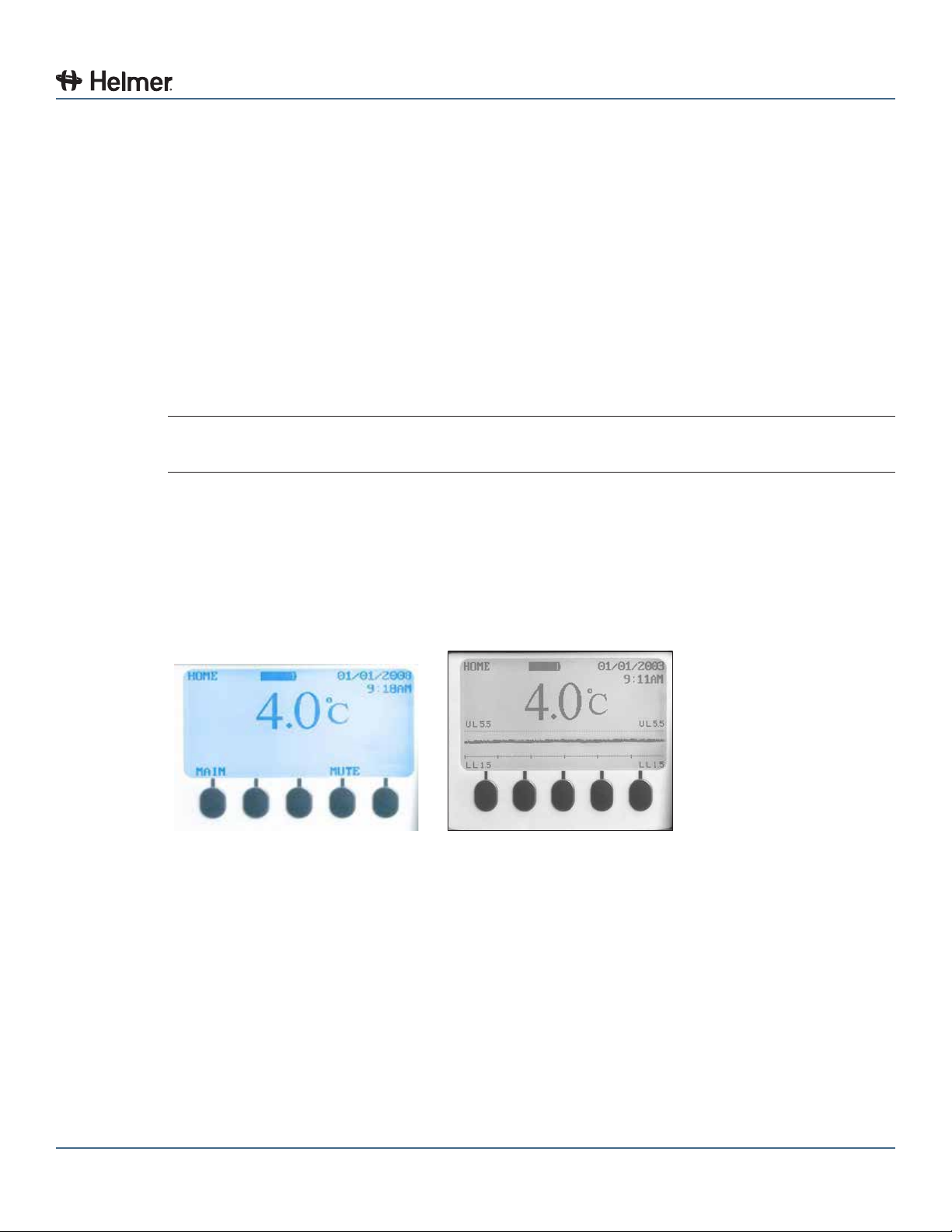
8.2 Normal Operation .....................................................................12
8.3 Change Temperature Setpoint ...........................................................13
8.4 Set Alarm Parameters ..................................................................14
8.5 Active Alarms.........................................................................14
8.6 Mute and Disable Active Alarms ..........................................................14
8.7 Light Operation .......................................................................14
9 i.Center Screen Reference .................................................. 15
10 Components .............................................................. 17
10.1 Front and Base .......................................................................17
10.2 Chamber ............................................................................18
10.3 Rear................................................................................19

360116-1/D iii
Section III: Horizon Series™ Models ..................................20
11 Operation ................................................................ 20
11.1 Initial Start Up ........................................................................20
11.2 Temperature Setpoints .................................................................20
11.2.1 Change Setpoint................................................................20
11.2.2 Monitor Offset..................................................................21
11.2.3 Control Sensor Offset............................................................21
11.2.4 Hysteresis.....................................................................21
11.2.5 Change a Temperature Alarm Setpoint ..............................................21
11.3 Active Alarms.........................................................................22
11.4 Mute and Disable Audible Alarms .........................................................22
11.5 Light Operation (Optional)...............................................................22
12 Components .............................................................. 23
12.1 Front and Base .......................................................................23
12.2 Chamber ............................................................................24
12.3 Rear................................................................................25

360116-1/D 4
General Information
Section I: General Information
1 About this Manual
1.1 Intended Audience
This manual is intended for use by end users of the refrigerator and authorized service technicians.
1.2 Model References
Generic references are used throughout this manual to group models that contain similar features. For
example, “105 models” refers to all models of that size (iB105, HB105, iLR105, HLR105). This manual
coversallundercounterrefrigerators,whichmaybeidentiedsingly,bytheirsize,orbytheirrespective
“Series.”
1.3 Copyright and Trademark
Helmer®, i.Series®, i.Center®, Horizon Series™, and Rel.i™ are registered trademarks or trademarks of
Helmer, Inc. in the United States of America. Copyright © 2014 Helmer, Inc. All other trademarks and
registered trademarks are the property of their respective owners.
Helmer,Inc.,doingbusinessas(DBA)HelmerScienticandHelmer.
2 Safety
Includes general safety information for refrigerator operation.
2.1 SafetyDenitions
The following general safety alerts appear with all safety statements within this manual. Read and abide
by the safety statement that accompanies the safety alert symbol.
WARNING The safety statement that follows this safety alert symbol indicates a hazardous situation
which, if not avoided, could result in serious injury.
CAUTION The safety statement that follows this safety alert symbol indicates a hazardous situation
which, if not avoided, could result in minor or moderate injury.
NOTICE The safety statement that follows this safety alert symbol indicates a situation which, if
not avoided, could result in damage to the product or stored inventory.
2.2 Product Labels
Caution: Risk of damage
to equipment or danger to
operator
Caution: Unlock all casters
Caution: Hot surface Earth / ground terminal
Caution: Shock/electrical
hazard
Protective earth / ground
terminal

360116-1/D 5
General Information
2.3 Avoiding Injury
► Review safety instructions before installing, using, or maintaining the equipment.
► Before moving unit, ensure door is closed and casters (if installed) are unlocked and free of debris.
► Before moving unit, disconnect the AC power cord and secure the cord.
► Never physically restrict any moving component.
► Avoid removing electrical service panels and access panels unless so instructed.
► Keep hands away from pinch points when closing the door.
► Avoid sharp edges when working inside the electrical compartment and refrigeration compartment.
► Ensure biological materials are stored at recommended temperatures determined by standards,
literature, or good laboratory practices.
► Proceed with caution when adding and removing samples from the refrigerator.
► Use supplied power cord only.
► UsingtheequipmentinamannernotspeciedbyHelmerScienticmayimpairtheprotection
provided by the equipment.
► Decontaminatepartspriortosendingforserviceorrepair.ContactHelmerScienticoryour
distributor for decontamination instructions and a Return Authorization Number.
► Ensure biological materials are stored safely, in accordance with all applicable organizational,
regulatory, and legal requirements.
► Therefrigeratorisnotconsideredtobeastoragecabinetforammableorhazardousmaterials.
3 General Recommendations
3.1 Intended Use
Helmerrefrigeratorsareintendedforthestorageofbloodproductsandothermedicalandscienticproducts.
3.2 General Use
Allow refrigerator to come to room temperature before switching power on.
NOTE During initial startup, high temperature alarm may sound while refrigerator reaches
operating temperature.
3.3 Initial Loading
Allow the refrigerator to reach room temperature before powering on. Allow chamber temperature to
stabilize at the setpoint before storing product.
NOTE Donotoverloadtopdrawer,basket,orshelfsuchthatairowfromtheunitcooleris
obstructed.

360116-1/D 6
General Information
4 Specications
iB105 iLR105 HB105 HLR105
Exterior Dimensions (1)
Height (2,3) 33.5” (851 mm)
Width 24” (610 mm)
Depth 28.5” (724 mm)
Physical
Weight 200 lbs (91 kg) 188 lbs (86 kg) 200 lbs (91 kg) 188 lbs (86 kg)
Interior Volume 5 ft³ / 142 L
Refrigeration System
Refrigerant R-134A (non-CFC)
Compressor 0.25 HP, air-cooled
Initial Charge 9.5 oz. (269 g)
Operational
Default Set Point 4 °C (39 °F)
Temperature Control Range 2 °C to 10 °C (36 °F to 50 °F)
Cabinet
Insulation High-density, non-CFC foam
Wall Thickness 2” (51 mm)
Door Thickness 2” (51 mm)
External Material Galvannealedsteelwithbacteria-resistantpowder-coatednish
Internal Material Galvannealedsteelwithbacteria-resistantpowder-coatednish
InteriorConguration(4) 2 drawers 2 shelves 2 drawers 2 shelves
Drawer, Shelf, or Basket Load 100 lbs (46 kg)
External Port 1, standard (top-left corner, rear of cabinet)
Temperature Chart Recorder (5) Standard Optional Standard Optional
Electrical
Input Voltage and Frequency 115 V; 230 V (50 Hz); 230 V (60 Hz)
Voltage Tolerance ±10%
Circuit Breakers 6 A (quantity 2, standard on 230 V models)
Power Consumption 5.0 A (115 V); 4.0 A (230 V, 50 Hz); 3.25 A (230 V, 60 Hz)
Power Source Grounded outlet, meeting national electric code (NEC) and local electrical requirements
Control and Monitoring
Interface Monitoring and display system; separate
temperature control system Temperature control and display system
Alarms
High, low, and condenser temperature;
door open; AC power failure; low battery;
no battery; probe failure; change chart paper
High and low temperature; door open;
AC power failure; probe failure
Remote Alarm Interface Dry contacts (standard)
Remote Alarm Capacity 0.5 A at 125 V (AC); 1 A at 250 V (DC) 10 A at 250 V (AC); 10 A at 125 V (AC);
5 A at 100 V (DC)
Environmental
Operating Standards
► Indooruseonly
► Altitude(maximum):2000m
► Ambienttemperaturerange:15°Cto32°C
► Relativehumidity(maximumforambienttemperature):80%fortemperaturesupto
31 °C, decreasing linearly to 50% at 40 °C

360116-1/D 7
General Information
(1) Includes features that protrude from the cabinet.
(2) With casters, height is approximately 35.5” (915 mm).
(3) With leveling feet fully engaged (minimum height), height is approximately 34” (864 mm). Maximum
height leveling feet may add is approximately 2” (51 mm).
(4) Bloodbankmodels(iBandHB)featuredrawersasthestandardstorageconguration.Laboratory/
pharmacymodels(iLRandHLR)featureshelvesasthestandardstorageconguration.Any
combination of drawers, shelves, or baskets may be installed.
(5) 4” (102 mm), 7-day inkless, pressure-sensitive chart paper, backup battery.
CAUTION ► The interface on the remote alarm monitoring system is intended for connection to
the end user’s central alarm system(s) that uses normally-open or normally-closed
dry contacts.
► If an external power supply exceeding 30 V (RMS) or 60 V (DC) is connected to the
remote alarm monitoring system’s circuit, the remote alarm will not function properly;
may be damaged; or may result in injury to the user.
NOTE In the event of a power failure, the power failure alarm condition is transmitted through
the remote alarm contacts.
4.1 Stacked Undercounter Units
WARNING ► Forastackedconguration,bothunitsmusthavelevelingfeetinstalled.
► The back brace bars and front stabilizing brackets must be installed.
► When stacking a refrigerator and freezer (104 and/or 105 models), place the heavier
unit on the bottom.
► Do not open multiple, loaded drawers or baskets at the same time.
Call Helmer or your distributor for more information on the stacking kit, and for methods to secure both
unitstothewalland/ortheoor.

360116-1/D 8
General Information
5 Compliance
5.1 Regulatory Compliance
This device complies with the requirements of directive 93/42/EEC concerning
Medical Devices, as amended by 2007/47/EC.
0086
Sound level is less than 70 dB(A).
EC REP Emergo Europe
Molenstraat 15
2513 BH
The Hague, Netherlands
5.2 WEEE Compliance
The WEEE (waste electrical and electronic equipment) symbol (right) indicates
compliance with European Union Directive WEEE 2002/96/EC and
applicable provisions. The directive sets requirements for the labeling and
disposal of certain products in affected countries.
When disposing of this product in countries affected by this directive:
► Do not dispose of this product as unsorted municipal waste.
► Collect this product separately.
► Use the collection and return systems available locally.
For more information on the return, recovery, or recycling of this product, contact your local distributor.
6 Installation
6.1 Location Requirements
► Has a grounded outlet meeting national electric code (NEC) and local electrical requirements.
► Is clear of direct sunlight, high temperature sources, heating vents, and air conditioning vents.
► Has a minimum of 3” (76 mm) of space behind the refrigerator for clearance and feature access.
► Meetsthelimitsspeciedforambienttemperatureandrelativehumidity.
6.2 Install AC Power Cord
WARNING Use supplied power cord only.
Install the power cord:
1 Insert the power cord into the receptacle on rear of the cabinet.
2 Install the power cord retainer to prevent accidental disconnection.
Power cord retainer (for refrigerators with casters installed).

360116-1/D 9
General Information
6.3 Placement
WARNING To prevent tipping, ensure the casters (if installed) are unlocked and the door is closed
before moving the refrigerator.
1 Ensure door is closed and casters (if installed) are unlocked.
2 Move refrigerator into place. Lock casters if installed.
3 Ensure refrigerator is level.
NOTE Helmer recommends the use of leveling feet (unless casters are installed).
6.4 Temperature Probes
For each probe bottle, use:
► Approximately 4 oz. (120 mL) of product simulation solution (10:1 ratio of water to glycerin).
6.5 Temperature Chart Recorder
A B F
C
D
E
Chart recorder with paper and battery installed.
Label Description Function
A Left and right buttons Adjust settings and stylus position
B LED Indicates status of chart recorder in operating mode, or selected
temperature range in paper change mode
C Chart change button Adjust position of stylus when changing chart paper, or run a test pattern
D Stylus Mark temperature line on paper
E Reset button Restart chart recorder
F Backup battery Provides power during AC power failure. Connect prior to use.

360116-1/D 10
General Information
6.5.1 Install and Change Chart Paper
1 Press and hold Cbutton.Whenstylusbeginstomoveleft,releasebutton.TheLEDashesto
indicate current temperature range.
2 When stylus stops moving, remove chart knob then move knob up and away from chart paper.
3 Place new chart paper on chart recorder.
4 Gently lift stylus and rotate paper so current time line corresponds to time line groove.
5 Hold chart paper and reinstall chart knob.
NOTE For accurate temperature reading, ensure that current time is aligned with time line
groove when chart knob is tightened.
6 Conrmthetemperaturerangeissettothecorrectvalue.
7 Press and hold C button. When the stylus begins to move right, release the button.
8 Conrmthestylusismarkingthetemperaturecorrectly.

360116-1/D 11
General Information
7 Maintenance Schedule
Maintenance tasks should be completed according to the following schedule. Refer to the service manual
for more detail on the various tasks.
NOTE These are recommended minimum requirements. Regulations for your organization or
physical conditions at your organization may require maintenance items to be performed
more frequently, or only by designated service personnel.
Task Frequency
Quarterly Annually As needed
Test the high and low temperature alarms.
Test the power failure alarm (as required by your organization’s
protocols).
Test the door alarm (as required by your organization’s
protocols).
Check the temperature calibration on the monitor and change it
if necessary.
(Models with chart recorders)
Check the backup battery for the chart recorder after an
extended power failure and change it if necessary, or change
the battery if it has been in service for one year. Refer to the
Temperature Chart Recorder Operation and Service Manual.
► Inspect electrical components and wiring terminals in the
electrical box for discoloration. Contact Helmer Technical
Service if any discoloration is found.
► Inspect all wiring for terminals for secure connection.
Tighten wiring terminal connections as necessary.
Checkthelevelofthesolutionintheprobebottle.Rellor
replace solution if necessary.
Examine the probe bottle and clean or replace if necessary.
Check the chamber lights and replace them if necessary.
Clean the condenser grill.
Clean the door gaskets, interior, and exterior of the refrigerator.
NOTICE Clean the condenser grill on a quarterly basis.
NOTE ► During a power failure, the backup batteries provide power to the monitoring system
and the power failure alarm. If the backup batteries are not functioning, the power
failure alarm will not be activated.
► If the backup batteries do not provide power to the monitoring system during the
power failure alarm test, replace the batteries.
► If battery (batteries) have been in service for one year, replace battery (batteries).

360116-1/D 12
i.Series® Models
Section II: i.Series®Models
8 Operation
8.1 Initial Start Up
1 Plug the power cord into a grounded outlet that meets the electrical requirements on the product
specicationlabel.
2 Switch AC ON/OFF switch ON.
3 Insert the D-cell backup battery in the monitoring system backup battery pack.
4 Select language.
a The SYSTEM OPTIONS screen is displayed.
b To select a different language, press the INC or DEC buttons until the preferred language is
displayed.Thisassumesthelanguagewaspreviouslyloadedfromtheashmemorycard.
c Press the HOME button. All text will display in the selected language.
NOTE Active alarms are displayed on the HOME screen. If an alarm condition other than High
Temperature occurs, refer to the service manual for troubleshooting.
5 If an alarm sounds, temporarily mute the alarm by pressing the MUTE button.
8.2 Normal Operation
The HOME screen displays temperature and alarm information, and provides buttons for reaching other
functions of the i.Center monitoring system. If the temperature graph is enabled, a graph of the chamber
temperature is displayed over time on the HOME screen. Temperature setpoints and calibration settings
areconguredthroughthetemperaturecontroller.
i.Center Home screen. i.Center temperature graph.

360116-1/D 13
i.Series® Models
8.3 Change Temperature Setpoint
Independent temperature controller.
NOTICE Parameter values are factory-preset and should not be changed unless directed by
Helmer Technical Service.
NOTE ► Default setpoint is 4.0 °C.
► When there is no interaction for 25 seconds, the temperature controller exits program
mode and returns to normal mode.
► The reference temperature displayed on the temperature controller may not be the
same as the temperature displayed on the i.Center monitor.
1 Observe the chamber temperature displayed on the i.Center.
2 Determine how much the refrigerator setpoint will be changed.
EXAMPLE ► Current setpoint is 4.0 °C
► Target setpoint is 4.5 °C
► Setpoint adjustment value is +0.5 °C.
3 On the temperature controller, press and hold the SET button.
4 While holding the SET button, press the UP or DOWN arrow buttons to change the temperature
setpoint by the same value as determined in step 2.
5 Release all buttons. The temperature setpoint is changed.

360116-1/D 14
i.Series® Models
8.4 Set Alarm Parameters
i.Center Home screen.
1 Press the MAIN button.
2 Press the DOWNbuttontohighlightEditConguration.PresstheSELECT button.
3 Press the DOWN button to highlight Alarm Setpoints. Press the SELECT button.
4 Press the DOWN button to highlight the desired alarm setting.
5 Press the INC or DEC buttons to set the alarm setpoint.
6 Press the BACKbuttontoreturntotheEditCongurationscreen,orpresstheHOME button to exit.
The new settings are saved.
8.5 Active Alarms
The HOME screen displays the number and type of alarms that are active.
Alarm Description
High Temperature Chamber temperature reading is above high temperature alarm setpoint
Low Temperature Chamber temperature reading is below low temperature alarm setpoint
Low Battery Battery voltage is low
No Battery Battery voltage is zero or battery (or batteries) has been removed
Power Failure Power to unit has been disrupted
Door Open Doorisopenbeyonduser-speciedduration
Condenser
Temperature
Condenser temperature reading is above condenser temperature alarm
setpoint
8.6 Mute and Disable Active Alarms
1 On the HOME screen, press the MUTEbuttononcetomuteanalarmforveminutes.
► “MUTE05”isdisplayed,indicatingthatveminutesremainonthemutetimer.
2 Each additional press of the MUTEbuttonaddsveminutesofmuting.
► The timer duration is changed, and the new time is displayed.
8.7 Light Operation
Press the Light ON/OFF button to turn the light on or off.

360116-1/D 15
i.Series® Models
9 i.Center Screen Reference
HOME screen
MAIN button
MAIN screen
MUTE button (changes mute timer)
LIGHT button (turns light on or off, if option installed)
MAIN screen
Event Log option
(Press the SELECT button)
EVENT LOG screen
System Alarm Test & Status option
SYSTEM ALARM TEST & STATUS screen
EditConguration option
(Enter the password)
CONFIGURATION screen
ViewConguration option
VIEW CONFIGURATION screen
Product/Company Information option
INFORMATION screen
EVENT LOG screen
EVENT LOG DETAIL screen
SYSTEM ALARM TEST & STATUS screen
Start High Alarm Auto Test option
Start Low Alarm Auto Test option
Cancel High or Low Test option
Chart Paper Days Left or Chart Paper Timer display
Door Status display
Condenser Temp display
CONFIGURATION screen
Set Date & Time option
SET DATE & TIME screen
System Options option
SYSTEM OPTIONS screen
Alarm Setpoints option
SET ALARM SETPOINT screen
Temperature Calibration option
TEMPERATURE CALIBRATION screen
Factory Default Settings option
FACTORY DEFAULT SETTINGS screen
Change Password option
(Enter a new password)

360116-1/D 16
i.Series® Models
SYSTEM OPTIONS screen
Language option
Date Format option
Alarm Volume option
Alarm Pulse option
Temperature Units option
Chart Paper Timer option
SET ALARM SETPOINT screen
High Alarm Setpoint option
Low Alarm Setpoint option
Cond. Alarm Setpoint option
Door Ajar Timeout option
Power Failure Timeout option
Temperature Graph option
TEMPERATURE CALIBRATION screen
Temperature probe display
Temperature option
VIEW CONFIGURATION screen
Clock Mode display
Date Format display
Door Ajar Timeout display
Pwr Failure Timeout display
High Alarm Setpoint display
Low Alarm Setpoint display
Cond. Alarm Setpoint display
Alarm Volume display
Alarm Pulse display
Chart Paper Days Left or Chart Paper Timer display
Temperature Graph display

360116-1/D 17
i.Series® Models
10 Components
10.1 Front and Base
E F G H I
A
B
C
D
Front and base features (iB105 model shown).
Label Description
A Chart recorder (standard on blood bank models, optional on
laboratory/pharmacy models)
B i.Center monitoring system
C Door handle with lock
D Leveling foot (standard; casters are optional)
E Monitoring system backup batteries
F Flash port
G Circuit breakers (230 V models only; knockouts shown on 115
V model)
H Temperature controller
I Main power switch

360116-1/D 18
i.Series® Models
10.2 Chamber
A
B
E
F
G
H
C D
Chamber features (multiple models shown).
Label Description
A Probe bottle
B Shelf (laboratory/pharmacy models)
C Roll out basket (optional)
D Drawer (blood bank models)
E Unit cooler with fan guard
F Chamber label
G Standard for adjusting storage components
H Slide for drawer or basket
NOTE Bloodbankmodels(iB)featuredrawersasthestandardstorageconguration.
Laboratory and pharmacy models (iLR) feature shelves as the standard storage
conguration.Anycombinationofdrawers,baskets,andshelvesmaybeinstalled.

360116-1/D 19
i.Series® Models
10.3 Rear
A
B
C
D
E
F
G
H
I
J
K
L
Rear features (iB105 model shown).
Label Description
A Insert for stacking bracket
B Drain line
C Compressor
DProductspecicationlabel
E Power connector
F Access port
G Rear panel
H Remote alarm interface
I i.Center monitoring system data port
J RS-232 COM port (optional)
K Power cord
L Condensate evaporator
Other manuals for i.series
10
This manual suits for next models
5
Table of contents
Other Helmer Refrigerator manuals

Helmer
Helmer i.series Installation and user guide

Helmer
Helmer i Series Installation and user guide

Helmer
Helmer i Series User manual

Helmer
Helmer i Series User manual

Helmer
Helmer iB105 User manual

Helmer
Helmer i.series User manual

Helmer
Helmer i.series User manual

Helmer
Helmer i.series User manual

Helmer
Helmer iBX080 Manual

Helmer
Helmer i.series User manual