manuals.online logo
Brands
  1. Home
  2. •
  3. Brands
  4. •
  5. HELVAR
  6. •
  7. Accessories
  8. •
  9. HELVAR SF-PIR-SW-01 User manual

HELVAR SF-PIR-SW-01 User manual

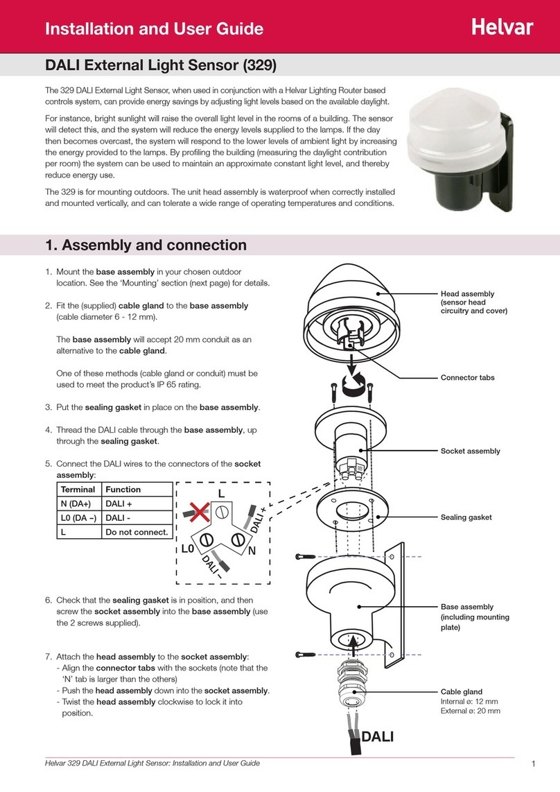
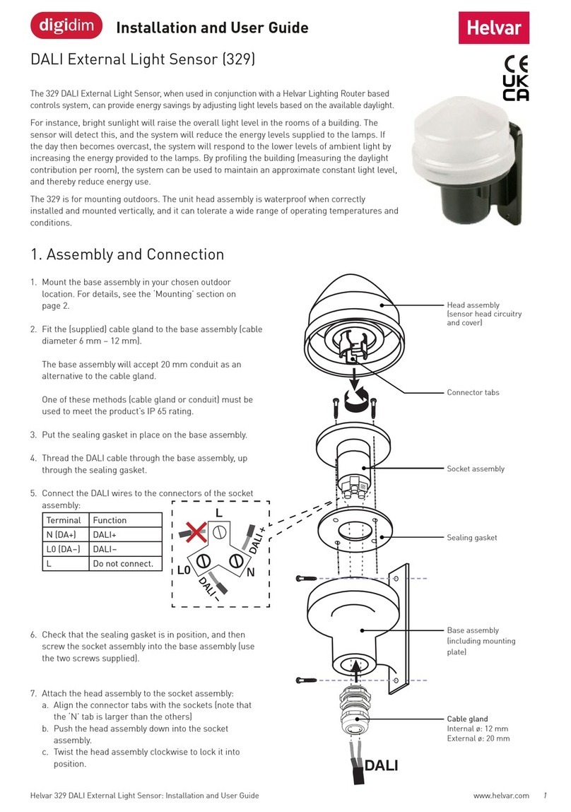
1Helvar Flush-Mount PIR Switching Sensor: Installation Guide
The SF-PIR-SW-01 is a PIR-triggered switch suitable for mounting into a ceiling void. It allows simple selection of presence or
absence detection to control both lighting and nonlighting loads.
Configurable for any room occupancy style, it switches on the connected load if the area is occupied and the illuminance is
lower than the specified level (with the photocell activated). Similarly, it switches off the load if the area is unoccupied for the
set time.
In absence mode, the unit can also be operated from a mains-rated retractive wall switch.
Flush-Mount PIR Switching Sensor (SF-PIR-SW-01)
Installation Guide
Features
230V. 50Hz
µ
AB PR
Sw
1
Helvar Flush Mount
PIR Switch.
Please refer to Installation
Guide for maximum loads.
HELVAR
SF-PIR-SW-01
www.helvar.com
Illuminance
threshold adjuster
Time adjuster
1000 lx
Photocell
inactive 10 lx
40 min
20 min
10 min
5 min
80 s
10 s
20 s
40 s
2,5 min2.5 min
Presence/Absence
mode selector
Presence Mode (Default Mode)
Out of the box, the time-out adjuster is set to 10 s, and the illuminance threshold adjuster is set to maximum (photocell
inactive). With the illuminance threshold adjuster set to maximum, the sensor will always switch on the connected load
when movement is detected. There are nine time periods available from the time-out adjuster (from 10 s to 40 min).
Multiple sensors can be connected to the same load in order to extend the detection zone (see ‘Multiple sensors’ on
page 2).
Absence Mode
With the mode selector set to absence detection mode, pressing a retractive switch connected to the sensor will switch
on the connected load. Then, if no presence is detected for the selected time period, or if the retractive switch is pressed
shortly, the load will be switched off.
Operation
2Helvar | Data is subject to change without notice.
2.8 m
7 m
Installation Notes
• Position the sensor so that the occupants of the room are normally inside the detection zone.
• Do not fix the sensor to an unstable or vibrating surface.
• Do not install the sensor within 1 m of any lighting, forced air heating, or ventilation equipment.
• Do not install several sensors in parallel near lamps that emit infrared radiation if these lamps are switched via another
PIR switch. This can cause false triggering.
• Make sure that the wires and cables are securely held within the connection terminals.
• Do not connect on a circuit with large inductive loads, as induced spikes can cause false triggering or damage the sensor.
• Protect the sensor by a 6 A MCB or fuse.
• Disconnect the sensor from the circuit before performing insulation testing of the wiring circuit.
L: Live in SW¹: Switch input (only in absence mode)
N: Neutral in SL: Switched live
Single sensor Multiple sensors
L
L
L
N
SW1SL
N
L
N
SL SL
SL
Mains-rated
retractive wall switch
~230VAC
Only available
in absence mode.
(Presence detection mode only)
Area
oflower
sensitivity
Area
ofhigher
sensitivity
Connections
www.helvar.com
Detection Pattern
3Helvar Flush-Mount PIR Switching Sensor: Installation Guide
Setup
Presence Mode
Auto on, auto off via time-out settings (no manual wall switch control). Multiple sensors can be connected to the same load
in order to extend the detection zone (see figure in section ‘Multiple sensors’ on page 2). When used in conjunctions
with illuminance settings, the load will only switch on if the detected light levels are below the minimum level set on the
illuminance threshold adjuster.
Absence Mode
Manual on via wall switch, auto off via time-out settings or manual off via wall switch. Single sensors only. Not for use with
multiple sensors in parallel.
Illuminance Setup
Notes: It is best to adjust the illuminance setting when the ambient light level is at the required minimum level.
For loads that should switch on regardless of ambient light levels, set the illuminance setting to maximum (photocell
inactive).
1. Set the illuminance setting to minimum and wait for the load to switch off.
2. Slowly increase the illuminance setting while waving your hand below the sensor until the connected load switches on.
Time Setup
Set the time appropriately for the usage of the area. For example, some possible settings could be:
• Offices with workers regularly walking: 20 min
• Offices with mainly desk-based workers: 40 min
• Corridors: 5 min
• Washrooms with total coverage: 10 min
• Washrooms with entry coverage only: 40 min
• 2D fittings: Not less than 20 min, due to potential lamp failure. If in doubt, contact your
lamp manufacturer.
Connection and Fixing
Attach
the cover
Connect the power
cable (and wall
switch in absence
mode only)
3. 4.
1. 2.
Squeeze the spring
coils together and
fit onto each of the
two lugs in turn
Then repeat the operation
with the other spring
Push the unit
into the ceiling void
⌀75 mm
Then centre it
about the hole
as required
4
Helvar Ltd
Hawley Mill
Hawley Road
DARTFORD
DA2 7SY
UNITED KINGDOM
www.helvar.com
Doc. 7860341, issue 2, 2015-12-15
Helvar | Data is subject to change without notice.
Conformity and standards
EMC emission: EN60669-2-1:2004 inc
A12:2010
EMC immunity: EN60669-2-1:2004 inc
A12:2010
Safety: EN60669-2-1:2004 inc
A12:2010
Environment: Complies with WEEE and RoHS
directives.
Version information
Hardware version: Rev. 1
Hole diameter: Ø 75 mm
2
60
7785
Dimensions (mm)
Technical Data
Electrical data
External power: Terminal block
Wire section: 0.5 mm² –
2.5mm² solid or stranded
Cable rating: All cables must be mains
rated.
Mains supply: 230 VAC, 50 Hz
Loads: 6 A resistive (e.g. heater)
4 A incandescent
3 A fluorescent ballast / LED
driver
1 A inductive (e.g. fan/motor)
Mains LED lamps: Equivalent
to 1000W halogen load
Min. load: 2 W resistive,
suitable for most energy saving
lamps, LEDs and emergency
fittings.
External
protection:
6 A maximum (MCB or fuse)
Illuminance: 10 lx to 1000 lx and maximum
(photocell inactive) at the PIR
switch.
Sensors
Presence detector: PIR (Passive InfraRed)
Detection range: 360° with up to 7 m diameter
when mounted at a 2.8m
ceiling height
Time: 10 s to 40 min
Mechanical data
Mounting hole
diameter:
75 mm
Bezel diameter: 85 mm
Recommended
clearance depth
(incl. 50mm for
cabling):
80 mm (without protective
cover)
100 mm (with protective cover)
Material (casing): Flame-retardant polycarbonate
Finish / Colour: Matt / White RAL9003
Weight: 100 g
IP code: IP20
Operating conditions
Ambient
temperature:
+10 °C to +35 °C
Note: The temperature
difference between the detection
target and the background must
be at least 4°C.
Relative humidity: Max. 90 %, noncondensing
Storage
temperature:
–10 °C to +70 °C
Other HELVAR Accessories manuals

HELVAR 329 User manual

HELVAR

HELVAR 329 User manual

HELVAR 32 TR Series User manual

HELVAR

HELVAR 32 TR Series User manual

HELVAR DIGIDIM 329 User manual

HELVAR

HELVAR DIGIDIM 329 User manual

HELVAR 320 User manual

HELVAR

HELVAR 320 User manual

HELVAR 322 User manual

HELVAR

HELVAR 322 User manual

HELVAR mDim series User manual

HELVAR

HELVAR mDim series User manual

HELVAR SS-PIR-SW-01 User manual

HELVAR

HELVAR SS-PIR-SW-01 User manual

Popular Accessories manuals by other brands

BEMKO SES60WH instructions

BEMKO

BEMKO SES60WH instructions

YEAZ BLACK RUN instruction manual

YEAZ

YEAZ BLACK RUN instruction manual

Paramotor PXP Meter manual

Paramotor

Paramotor PXP Meter manual

ETC Echo Dual Tech Wall-mount Vacancy Sensor installation guide

ETC

ETC Echo Dual Tech Wall-mount Vacancy Sensor installation guide

Siemens QAA2391.EWTC installation instructions

Siemens

Siemens QAA2391.EWTC installation instructions

SCHUNK FTN Commissioning instructions

SCHUNK

SCHUNK FTN Commissioning instructions

ProMed HKP-1.6 XL Instruction leaflet

ProMed

ProMed HKP-1.6 XL Instruction leaflet

Sigfox Sens’it 3 series user manual

Sigfox

Sigfox Sens’it 3 series user manual

Festo Span Series operating instructions

Festo

Festo Span Series operating instructions

Bernard Liners SPEC L-1.2 Specification sheet

Bernard

Bernard Liners SPEC L-1.2 Specification sheet

Golfzon SM200 manual

Golfzon

Golfzon SM200 manual

Interlogix TX-6010-03-1 Installation sheet

Interlogix

Interlogix TX-6010-03-1 Installation sheet

Show home ZW1102 quick start guide

Show

Show home ZW1102 quick start guide

Orion 8684 instruction manual

Orion

Orion 8684 instruction manual

Amphenol Temposonics MH Series operating manual

Amphenol

Amphenol Temposonics MH Series operating manual

Eaton CWPD Series Wiring and installation manual

Eaton

Eaton CWPD Series Wiring and installation manual

Camfil AIR IMAGE user guide

Camfil

Camfil AIR IMAGE user guide

Carefree Universal Eclipse installation manual

Carefree

Carefree Universal Eclipse installation manual

manuals.online logo
manuals.online logoBrands
  • About & Mission
  • Contact us
  • Privacy Policy
  • Terms and Conditions

Copyright 2025 Manuals.Online. All Rights Reserved.