2 Great Valley Blvd., Wilkes-Barre, PA 18706
Office Ph: 570-820-8811
Fax: 570-820-8838
www.itohdenki.com
HB-510N/P
Designed to be functional with the FS and
FE series motors, as well as the higher
torque series FP
Run Hold timer added to the Forcible RUN
input
Now there is no need for an external
controller/timer with, or awkward
positioning of, a second sensor used for
infeeding the conveyor
Specifications subject to change without notice
Integral indexed rotary switch provides easy
speed adjustment without the need for
“tweaking”
More LED functionality to communicate
operating and error statuses
Selectable automatic or manual recovery for
thermal overload protection
Motor lock protection shuts motor down if it is
locked for at least 4 seconds
Lead free design for RoHS conformity
What's New:
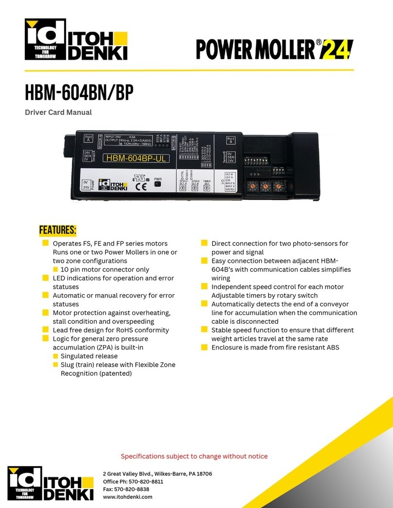
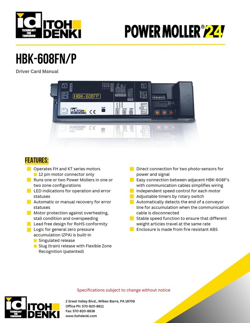
Driver Card Manual
Features:
Logic for general zero pressure
accumulation (ZPA) control is built-in
Direct connection for a photo-sensor to
both power it and receive its output signal
Easy connection between adjacent HB-
510s with communication cables
simplifies wiring
Selectable singulated or slug (train)
release modes for ZPA function
Flexible Zone Recognition (patented) to
handle long articles which simultaneously
block multiple sensors
Only available in slug release mode
Synchronized speed variation to
simultaneously adjust the speed of the rollers
with a single external speed control signal
Stable speed function to ensure that different
weight articles travel at the same rate
As long as the load does not exceed the
rated torque for a given speed
Enclosure is made from fire resistant ABS

