Regal Seepex IntelliGear Plus MD Manual

F O R M
Installation and Maintenance Manual
For IntelliGear Plus™ MD and BW1/BW2
Variable Speed Drives
9178E
Revised
October 2015
Power Transmission Solutions
Regal Beloit America, Inc.
7120 New Bufngton Road
Florence, KY 41042
Application Engineering: 800 626 2093
www.RegalPTS.com
• Periodic inspections should be performed. Failure to perform proper maintenance
can result in premature product failure and personal injury.
• Read and follow all instructions carefully.
• Disconnect and lock-out power before installation and maintenance.
Working on or near energized equipment can result in severe injury or death.
• Do not operate equipment without guards in place. Exposed equipment can
result in severe injury or death.
®c e
c
UL Listed
E211799
Ind. Cont EQ. 54 DN
us

IntelliGear PlusTM Variable Speed MD Gearmotors
2 MCIM15103E • Form 9178E • Printed in USA
Thank you for choosing an IntelliGear Plus Gearmotor.
• All electrical work should be performed by qualied
personnel and compliant with local and national electrical
codes.
• Periodic inspections should be performed. Failure to
perform proper maintenance can result in premature
product failure and personal injury.
• Read and follow all instructions carefully.
• Disconnect and lock-out power before installation and
maintenance. Working on or near energized equipment
can result in severe injury or death.
• Disconnect power at least 2 minutes prior to servicing to
allow capacitors to discharge. Handling wires sooner than
this could result in electric shock, severe injury, or death.
• Do not operate equipment without guards in place.
Exposed equipment can result in severe injury or death.
• Any eyebolts that have been supplied with the breakmotor
or gearmotor are designed for lifting only these
components. Lifting additional weight attached to theses
components may break the eyebolt and result in personal
injury or death, and product damage.
• IntelliGear Plus contains parts sensitive to static
electricity. Care should be taken to discharge static prior
to handling these components to avoid damage to them.
• Contact Regal Power Transmission Solutions for
recommendations for units running at slow speeds or
unusual conditions.

IntelliGear PlusTM Variable Speed MD Gearmotors
MCIM15103E • Form 9178E • Printed in USA 3
Contents
1 General Information................................................................................................................................................ 4
1.1 General operating principle....................................................................................................................................... 4
1.2 Product name............................................................................................................................................................ 4
1.3 Environmental characteristics ................................................................................................................................... 4
1.4 Radio-frequency interference.................................................................................................................................... 5
1.4.1 General ..................................................................................................................................................................... 5
1.4.2 Standards (Emissions).............................................................................................................................................. 5
1.4.3 Standards (Immunity)................................................................................................................................................ 5
1.5 Description of cables and protection devices (Customer Supplied).......................................................................... 5
1.6 UL conformity ............................................................................................................................................................ 5
1.6.1 Specied mains supply ............................................................................................................................................. 5
1.6.2 Cables....................................................................................................................................................................... 5
1.6.3 Fuses ........................................................................................................................................................................ 5
1.8 Dimensions ............................................................................................................................................................ 6-7
2 Installation ............................................................................................................................................................... 8
2.1 General ..................................................................................................................................................................... 8
3 Connections ............................................................................................................................................................ 8
3.1 Control Terminal Blocks ............................................................................................................................................ 8
3.2 Power terminal blocks............................................................................................................................................... 8
3.3 Wiring diagram based on standard conguration ..................................................................................................... 9
3.4 Terminal Block Assignments and MD Functionality ................................................................................................ 10
4 Commissioning ..................................................................................................................................................... 10
5 Faults - Diagnostics...............................................................................................................................................11
5.1 Troubleshooting Guide.............................................................................................................................................11
6 Gear Lubrication ................................................................................................................................................... 12
7 Gear Parts List ...................................................................................................................................................... 13
8 Motor Parts List..................................................................................................................................................... 14

IntelliGear PlusTM Variable Speed MD Gearmotors
4 MCIM15103E • Form 9178E • Printed in USA
1 - General Information
1.1 - General operating principle
The IntelliGear Plus is a combination of a 3-phase induction motor and an integrated open loop vector variable speed
drive. The motor can be combined with many gear types from Regal Power Transmission Solutions range.
In the standard product version, the integrated drive does not require any connection other than the power supply. The
options may be used to broaden the application range of the IntelliGear Plus.
IntelliGear Plus motors meet the requirements of the Low Voltage Directive 73/23/EEC, modied by 93/68/EEC. The
harmonized standards of the DIN VDE 0160 series in connection with standard VDE 0660, part 500 and EN 60146/VDE
0558 are also applicable.
1.2 - Product name
1.3 - Environmental Characteristics
115V Single Phase Power Supply 230V Single Phase Power Supply
Rating Power (HP) Rating Power (HP)
310 M 050 0.50 31 M 050 0.50
32 M 075 0.75 31 M 075 0.75
IntelliGear PLUS Controlling Options
Designation Description
RP1 4-20 mA follow or local Start/Stop/10 Turn Potentiometer
Characteristics Level - IntelliGear PLUS
Degree of protection TEFC Version TEFC motor and NEMA 4/12 Controller
Storage temperature -40 oC to +70 oC
Transport temperature -40 oC to +70 oC
Ambient operating temperature -20 oC to +40 oC (above 40 oC requires derating 1% per oC
Altitude Up to 3000 feet above sea level without derating
Ambient humidity 95% non-condensing
Humidity during storage 93%, 40 oC, 4 days
Vibration
Shocks
Immunity Conforming to EN61000-6-2
Radiated and conducted emissions Conforming to EN500081-2 with internal lters
UL (USA) Conforming to UL 508 C (E211799)
CUL (CANADA)
IntelliGear PLUS Accessories
Designation Description
KEYPAD LCD Parameter setting console w/cable to locally reprogram to customize parameters
VMA30SOFT CD w/cable and USB to locally reprogram to customize parameters

IntelliGear PlusTM Variable Speed MD Gearmotors
MCIM15103E • Form 9178E • Printed in USA 5
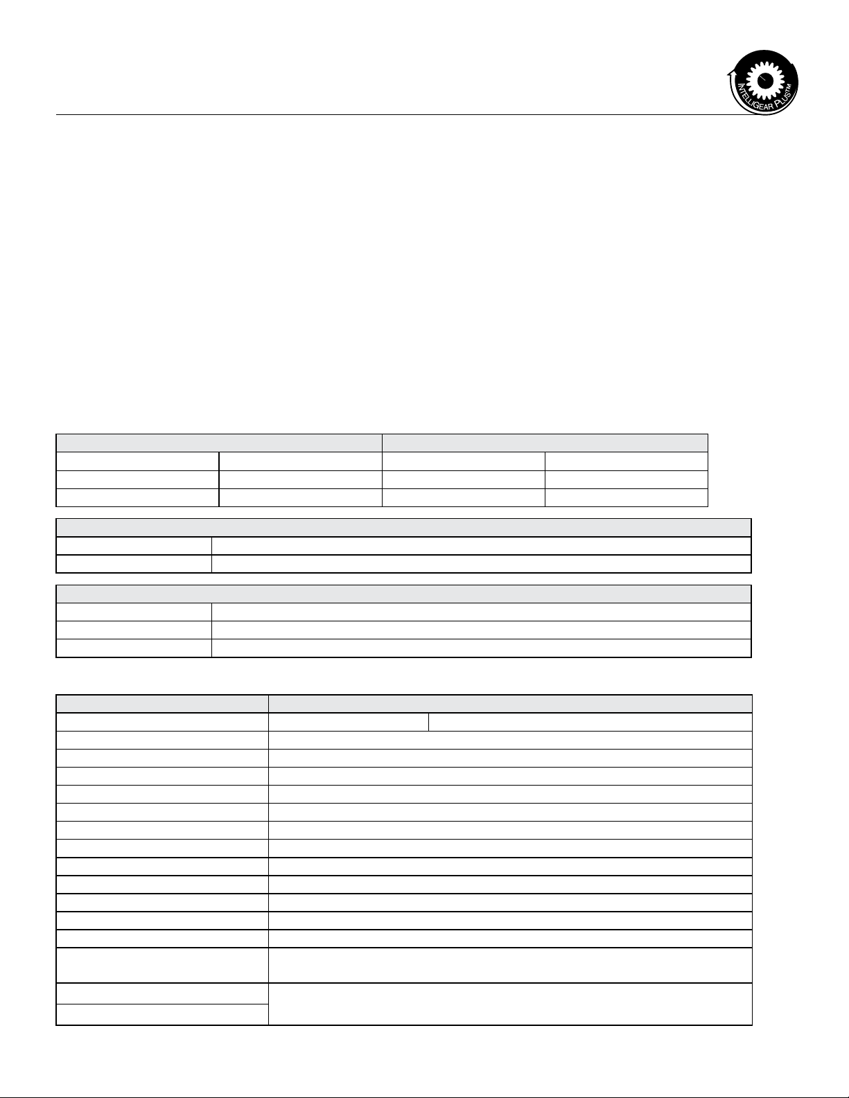
1.5 - Description of cables and protection devices (Customer Supplied)
NOTICE: When using a circuit-breaker, it must be a motor circuit-breaker (D curve).
• Comply with the size of protection fuses.
• The cable size may vary according to legislation applicable in the country, which will take precedence over the values
given in the table below without exception.
1.6 - UL conformity
1.6.1 Special mains supply
The drive can be incorporated in an installation with short circuit capacity of 5000 A rms maximum at voltage 264 VAC rms
maximum for 230 V (TL) drives or 528 VAC rms maximum for 400 V (T) drives.
1.6.2 Cables
Only class 1 copper cables 60/70° C (140/167° F) should be used.
1.6.3 Fuses
UL conformity is adhered to if the fuses are UL-listed, fast-blow fuses (class CC up to 30 A) with a rating as indicated in
the above table and if the short-circuit symmetrical current does not exceed 5 kA.
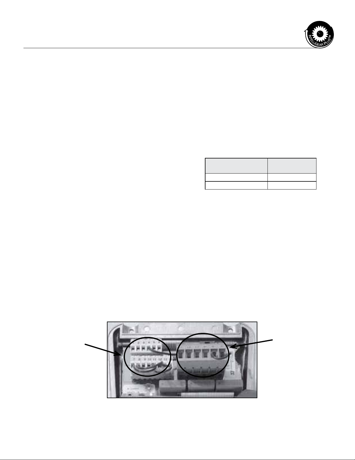
1.4 - Radio-frequency interference:
1.4.1 - General
Variable speed drives use high-speed switches (transistors,
semi-conductors) which switch high voltages (around 660V
for 3-phase drives) at high frequencies (several kHz). This
provides better efciency and a low level of motor noise. As
a result, they generate radio-frequency signals which may
disturb operation of other equipment or distort measurements
taken by sensors:
• due to high frequency leakage currents which escape to
ground via the stray capacity of the drive/motor cable and
that of the motor via the metal structures which support
the motor
• by conduction or feedback of R.F. signals on the power
supply cable; conducted emissions
• by direct radiation near to the main supply power cable
or the drive/motor cable: radiated emissions
These phenomena are of direct interest to the user. The
frequency range concerned (radio-frequency) does not affect
the energy distribution company.
1.4.2 - Standards (Emission)
The maximum emission level is set by (EN 50081-2) and
(EN 50081-1). IntelliGear Plus conforms to:
• EN 50081-2 as standard
• EN 50081-1 with lter option
1.4.3 - Standards (Immunity)
The maximum immunity level is set by (EN 50082-2) and
(EN 50082-1). IntelliGear Plus conforms to:
• EN 50082-2 and EN 50082-1 as standard
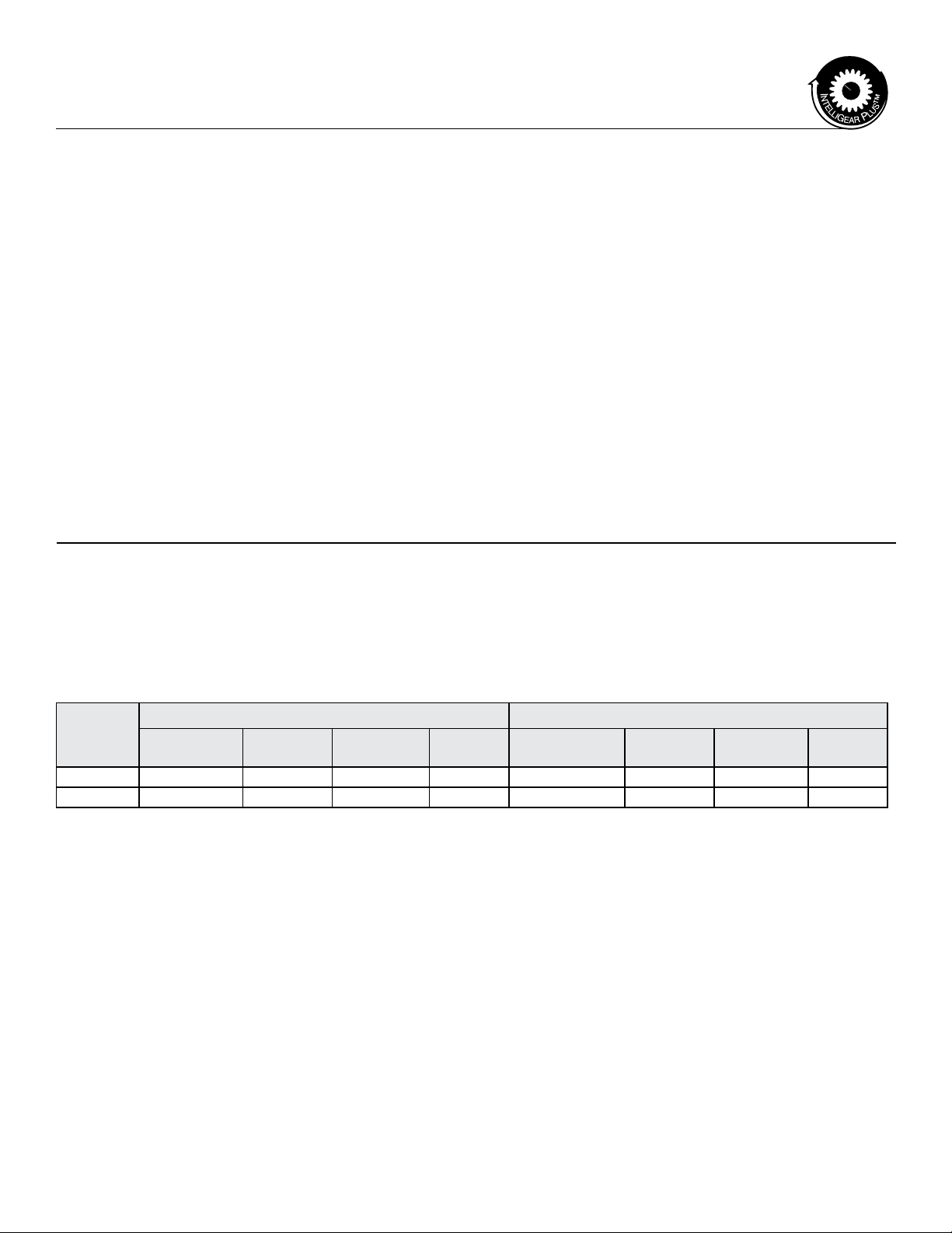
Motor 115V Single Phase Power Supply 230V Single Phase Power Supply
HP Rating IntelliGear
Plus Number Input Amps Wire Gauge Fuse Size IntelliGear Plus
Number Input Amps Wire Gauge Fuse Size
0.50 I 310M 050 5 14AWG 10 A I 31M 050 2.5 14AWG 8A
0.75 I 32M 075 8.5 14AWG 14A I 31M 075 4 14AWG 8A

IntelliGear PlusTM Variable Speed MD Gearmotors
6 MCIM15103E • Form 9178E • Printed in USA
1.8 - Dimensions
8.52
.39
.12
6.30
5.00
Ø .344 + .007 / -.002 HOLES
Ø 4.72
Ø 3.94
5.90
11.23
3.50
1.40
5.50
Ø .280 HOLES
4 @ 90º AS SHOWN
Ø 3.1500
3.1493
CATALOG NUMBER
CBN3001BSCB524.556 CCI 109
CCI NUMBER
CCI 109-G

IntelliGear PlusTM Variable Speed MD Gearmotors
MCIM15103E • Form 9178E • Printed in USA 7
CATALOG NUMBER CCI NUMBER
SEEPEXBW2+TS1LS80B14 CCI0109G

IntelliGear PlusTM Variable Speed MD Gearmotors
8 MCIM15103E • Form 9178E • Printed in USA
2 - Installation
After connection, ensure that the seals are rmly in place,
and that the screws and cable glands are watertight to ensure
drive protection. Clear any condensation from the drain holes
at the bottom of the motor.
2.1 - General
The IntelliGear Plus is usually tted to the gear and mounted
to the machine with ange or foot mounting. The motor fan
cools the whole assembly. Make sure that the ventilation air
inlet is free of obstruction. The positions of the potentiometer/
cable gland supports are specied at the time of ordering.
However they may be reversed if necessary.
3 - Connections
Connection with copper conductor only.
3.1 - Control Terminal Blocks
• Remove the terminal block from it’s xed holder
(unplugged) before making any connections, to avoid
putting pressure on the card.
CAUTION: The IntelliGear Plus has a positive logic
conguration. Using a drive with a control system which
has a different control logic may cause unwanted starting
of the motor.
• The control circuits in the drive are isolated from
the power circuits by single insulation (IEC 664-1).
• The installer must ensure that the external control
circuits are isolated against any human contact.
• If the control circuits need to be connected to circuits
conforming to SELV safety requirements, additional
insulation must be inserted to maintain the SELV
classication.
Removable screws in terminal block:
• Tightening torque = 2.62 in. lbs.
• Maximum cross section = 17 AWG
3.2 Power terminal blocks
3.2.1 Terminal block for power supply PB1
(marked L&N)
This terminal block is used to connect the 3 phase
power supply when the RFI lter is not used in an
IntelliGear Plus. Otherwise, the RFI lter output
is screwed onto this connector and the power
supply should be attached to the terminals located
on top of the lter. (See table below)
Screw terminal
blocks Frame 310M
Tightening Torque 7.1 in. lbs.
Max. cross-section AWG 14
Numbered Controller
Terminal Blocks
Terminal Block
for Power Supply

IntelliGear PlusTM Variable Speed MD Gearmotors
MCIM15103E • Form 9178E • Printed in USA 9
3.3 Wiring diagram based on standard conguration
NOTE:
IF AUTO MODE RUN/STOP CONTACT IS NOT USED, 4-20mA INPUT
CONNECTOR PINS 5 & 6 MUST BE JUMPERED TO RUN IN AUTO
MODE.
User supplied male Turck connectors can be secured locally using the
following information -
4 pin connector with 4 meter cable attached = Turck # SB4T - 4
5 pin connector with 4 meter cable attached = Turck # SB5T - 4
6 pin connector with 4 meter cable attached = Turck # SB6T - 4

IntelliGear PlusTM Variable Speed MD Gearmotors
10 MCIM15103E • Form 9178E • Printed in USA
3.4 Terminal block assignments and MD functionality
Controller
Terminal
Number
Designation Function Characteristics
110V +10V analog internal source Accuracy ± 2%
Maximum output current 30 mA
Voltage input
2 ADI1 Hand Mode Speed Reference Full scale voltage 10 V ± 2%
** Input Impedance 95 kΩ
30V Logic circuit common 0V
Current input
Current range 0 to 20 mA ± 5%
4 ADI2 Auto Mode Speed Reference Input impedance 500 Ω
Resolution 10 bits
Sampling 6 ms
Logic input (if connected to the +24 V)
6ADIO3 Fault Signal Input Threshholds “0”:<5V-”1”; >10V
From Pump Operation Voltage range 0 to +24V
Run Dry and/or High Pressure Load 95 kΩ
Input threshold 7.5V
Characteristics Digital output 1
7DIO1 Alarm LED Threshholds “0”:<5V-”1”; >10V
Voltage range 0 to +24V
Sampling/refreshment 2 ms
5Output current 10 mA in total
Overload current 33 = 150mA, 31/32 = 50mA
24V +24V internal source Accuracy ± 5%
11 Protection Current limiting and overload
fault trip
Logic input 2 Characteristics Logic input (positive logic)
8 DI2 Run/Stop Threshold “0”:<5V-”1”; >10V
Voltage range 0 to +24V
Logic input 3
Motor Thermal Input
Sampling/refreshment 2 ms
9 DI3 Absolute maximum voltage 0 to +35V
range
Logic input 4
Hand Mode Selectior
Load 15 kΩ
10 DI4 Input threshold 7.5V
Voltage range 9 to + 35V
12 ENA Enable Impedance 820 Ω
13 RL1 Drive Healthy Contact
N/C after start-up if OK
Characteristics
250VAC maximum contact
current
NO single pole contact
14 RL2 4 A, resistive load
2 A inductive load
** Performs scaling function when drive is programmed for full PI mode of operation
4. Commissioning
WARNING! Before switching on the IntelliGear Plus unit, check that the electrical
connections are correct, and that any moving parts are mechanically guarded.
WARNING! For the safety of personnel, the IntelliGear Plus must not be switched
on with any protective covering removed.

IntelliGear PlusTM Variable Speed MD Gearmotors
MCIM15103E • Form 9178E • Printed in USA 11
5. Faults - Diagnostics
Information relating to the status of the IntelliGear Plus is provided by an indicator lamp (see photo bottom
right) on the control and by the internal LED in 310M.
D
é
faut d’uentrainement
Falla en el impulsor
DRIVE FAILURE
Haute pression
Alta presión
HIGH PRESURE
ROUGE
ROJO
RED
D
é
faut d’enroulement
falla en el bobinado
WINDING FAILURE
Débit bas
Bajo flujo
LOW FLOW
sur/sous tention
Alto/Bajo Voltage
OVER/UNDER VOLTAGE
Temp
é
rature
é
lev
é
e
Temperatura excesiva
OVER TEMP
Entrainement & puissance
Impulsion & Potencia
DRIVE & POWER
Pompe
Bomba
PUMP
Falla potencial / Defaut potentiel
POTENTIAL FAULT
TOUTE INTERVENTION
MINUTES AU MOINS AVANT
TENSION ET ATTENDRE 2
METTRE L’APPAREIL HORS
ADJUSTMENTS
BEFORE MAKING
AT LEAST 2 MINUTES
DISCONNECT POWER
DE INTERVENIR
2 MINUTOS ANTES
Y ESPERAR AL MENOS
DESCONECTAR EL APPARATO
CAUTION :RISK OF ELECTRIC SHOCK
seepex Inc.
Tel +1(937)864-7150
Fax +1(937)864-7157
5. 1 MD Gearmotor Troubleshooting Guide
Symptom Probable Cause(s) Actions Required
Not running in AUTO or HAND mode-
Alarm Light not lit
Power to drive is not on Check power supply and cord
HOA switch is in “OFF” position Move switch to HAND or AUTO
Not running in AUTO mode - HOA switch not in “AUTO” position Put HOA switch in “AUTO” position
Alarm light not lit Pins “5” and “6” of the six pin Turck
connector are not “connected”
• Connect Auto Mode Run/Stop contact to
pins “5”and “6” of six pin Turck connector.
• Make sure Auto Mode Run/Stop contact
is closed.
• Jumper pins “5” and “6” if Auto Mode
Run/Stop contact is not being utilized
Unit runs at only Low Speed in
AUTO mode
4-20 mA signal is not present at drive Check incoming 4-20 mA signal
4-20 mA to drive installed in reverse into
pins “1” and “2” of six pin Turck connector
Reverse 4-20 mA connection polarity
Unit in AUTO mode will not achieve
high RPM output at 20 mA
4-20 mA signal does not achieve full scale Check incoming 4-20 mA signal
Signal to drive is not reaching full 20 mA Repair signal
Potentiometer is not in “10” position Turn potentiometer to “10” position
Red LED “Alarm” light is on -
Unit has stopped
Refer to “badge” below and on top of unit
for mechanical/pump and electrical/
motor causes
Check these causes to determine the
root cause for fault. Once cleared, un-
plug and re-install main power plug with
power source

IntelliGear PlusTM Variable Speed MD Gearmotors
12 MCIM15103E • Form 9178E • Printed in USA
6 - Gear Lubrication
Series 3000 CbN gearing is shipped with one of the following synthetic lubricants per the table below. The gear reducer
has been lled to accommodate any mounting position. In the case of synthetic oil, the lubricant does not require
changing, but it is recommended that proper oil level be checked periodically.
Acceptable Mineral Oil Lubricants
Synthetic
Orient the gear head
vertically and ll to
mid-point of the Pri-
mary Gear
Primary
Gear
Input
Opening
Diagram for
Size 30
Oil Level
Fuchs is a registered trademark of Fuchs Petrolub; Shell is a registered trademark of Shell Petroleum
Incorporated. Omala is a registered trademark of Shell Trademark Management.
Ambient Range of Installation
-4˚ F to 14˚ F
(-20˚C to 10˚C)
14˚F to 122˚F (-10˚C to 50˚C) 122˚F and Above
(50 ˚C+)
No Backstop With Backstop
ISO VG 68 ISO VG 100 ISO VG 150 ISO VG 220 ISO VG 150 ISO VG 320
Manufacturer -25˚ F to 125˚ F
(-30˚ C to 50˚ C)
Fuchs®Sintogear® 125
Mobil®SHC 629
Shell®Omala® Fluids HD 150
Manufacturer -25˚ F to 125˚ F
(-30˚ C to 50˚ C)
Shell Omala RL 100
No Backstop With Backstop

IntelliGear PlusTM Variable Speed MD Gearmotors
MCIM15103E • Form 9178E • Printed in USA 13
Typical Maintenance Items - Bearings and Seals
Rep Description Quantity
001 Housing 1
009 Output ang ring 1
031 Output shaft 1
042 Pinion 1
052 Gear 1
061 Bearing front 1
062 Bearing back 1
077 Output shaft key 1
080 Gear Key 1
Rep Description Quantity
090 Oil seal 1
097 Input o-ring 1
127 Gearing snap ring* 1
130 Gearing snap ring 1
175 Input bracket screw 4
185 Washer for gear* 1
186 Screw washer* 1
187 Bolt 4
282 Nameplate 1
Gear
Frame
Item Description By Location
Bearings Seal (mm)
61 62 90
30 6205 ZZ 6005 25 x 52 x 7 DL nitrile
* Not illustrated on diagram
052
097
255
001
282
284
062
080
031
077
061
130
090
009
187
257
256
258
128
042
7.0 - Gear Parts List
CBN 3001

32
1
5
6
4
9
8
10
11
183
184
254
7
CbN 30 (Quantity Per Unit)
FRAME 56
Part # Description Qty.
1Fan Cover 1
2Self Tapping Screw 3
3Hex Nut 1
5Retaining Snap Ring 1
6 Fan 1
7Bracket 1
8 Screw 4
9Bushing 4
10 Plastic Plug 4
11 Ball Bearing 1
12 Rotor Assembly (includes items 13 & 14) 1
13 Shaft 1
14 Rotor Core 1
15 Wound Stator Assembly 1
16 Gasket 1
17 Outlet Box Base 1
18 Self Tapping Screw 2
19 Outlet Box Cover 1
20 Self Tapping Screw 2
Rep Description Quantity
1Motor adapter 1
2Input shaft 1
3 Pinion 1
4Internal snap ring 1
6 Bearing 1
8External snap ring 1
9 Seal 1
10 Pinion pin 1
183 Stud 4
184 Nut 4
Gear
Frame
Bearing Seal (mm)
6 9
30 6005 2RS 47 x 25 x 7
IntelliGear, IntelliGear Plus & Design are trademarks of Regal Beloit Corporation or one of its afliated companies.
UL is believed to be a registered trade name and/or trademark of Underwriters Laboratories, Inc. and is NOT owned or controlled by Regal Beloit America Inc.
©2015 Regal Beloit Corporation, All Rights Reserved. MCIM15103E • Form 9178E • Printed in USA
This manual suits for next models
2
Table of contents
Other Regal DC Drive manuals
Popular DC Drive manuals by other brands

Inovance
Inovance MD520 Series installation guide

SEW-Eurodrive
SEW-Eurodrive MOVI4R-U operating instructions

KEBCO
KEBCO COMBIVERT F6 Instructions for use

Wittenstein cyber motor
Wittenstein cyber motor cyber reaction wheel 2 Planning guide

Minarik
Minarik RG501A user manual

Selve
Selve Commeo SE Pro-RC quick start guide