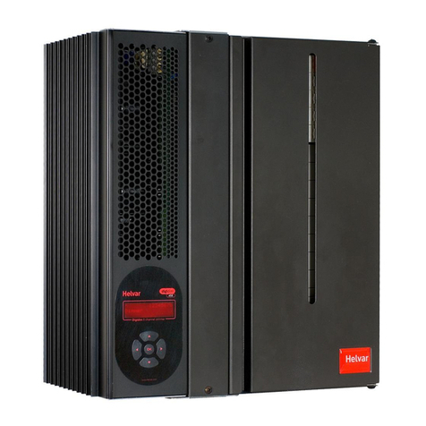
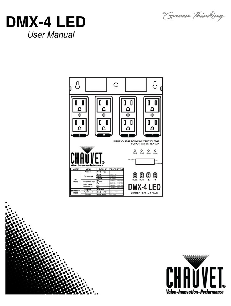
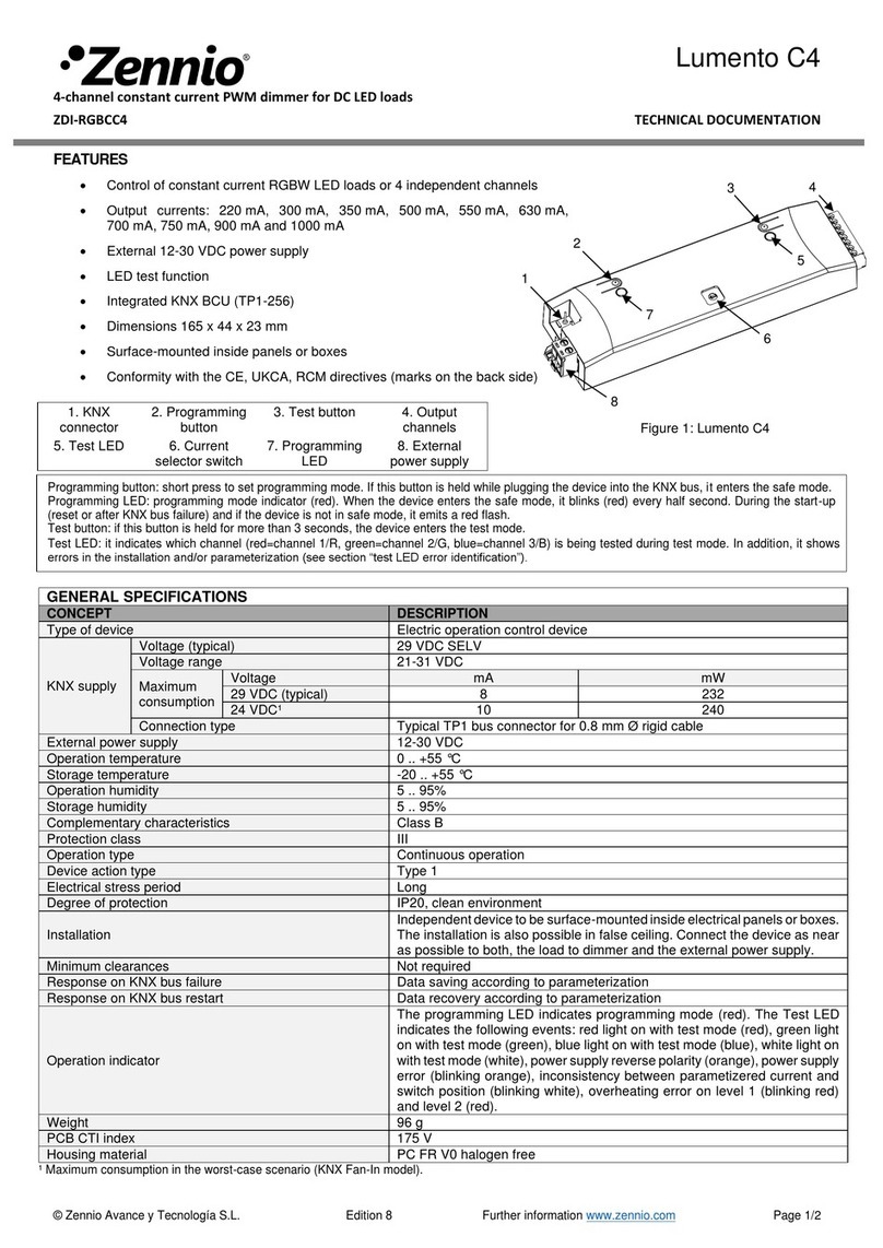
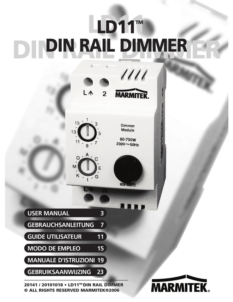
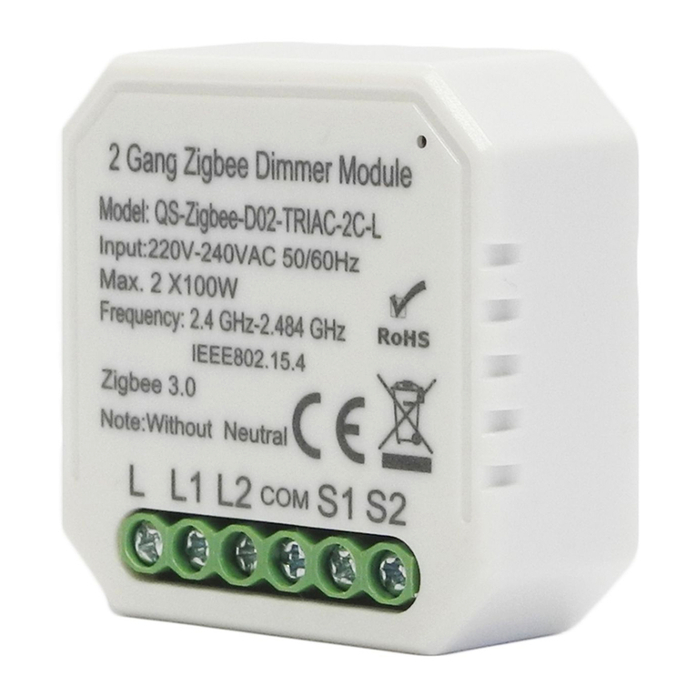
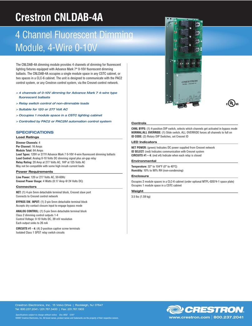
HELVAR HES99300 User manual

Installation & User Instructions
4 Channel Dimmer
HES99300
The Helvar Electrosonic HES99300 is a four channel
dimmer unit having a total current capacityof 10A. The
dimmer can control the following load types: incandescent
lamps, low voltage halogen lamps with dimmable
conventional and electronic transformers, 26 mm
fluorescent tubes or compact fluorescent tubes with Helvar
EL-FD electronic ballasts, and 3 wire dimming ballasts for
fluorescent tubes.
The dimmer can be controlled with the Ambience Master
Panels or from a Helvar Electrosonic Imagine system, or
from 0-10V analogue rotary controls or sliders. Remote
panels including one infra-red remote control can be
connected to the Master Panel.
Easy light level adjustment of the four channels is done
directly from the Master Panels. The minimum level and the
fade time adjustment of the dimmer is carried out at the
panel.
245
181
93
251
63
211
230
HES99300 4 CHANNEL DIMMER
Technical Data
Mains voltage: 200-250v AC single phase
100-130v AC single phase (to special order)
Mains frequency: 45 - 65 Hz
Mains quality: all data is based on a pure sinusoidal mains supply,
Mains signalling filtering: over 400 Hz mains signals are filtered
Output relay: single 1 pole 10A output relay
Compensation of output voltage: variation 3%, with supply voltage variation of 10 %
Nominal load: 2300 VA - max total load.
Power factor of load: min. 0.5 inductive
Conformity & Standards
EMC: Generic emission: EN 50 081 part 1
Generic immunity: EN 50 082 part 1
RFI: EN 55 014, SETI T33-91 and VDE 0875 Teil 2
Safety: Safety: EN 60 950
Isolation: 4kV
IP rating: 305
Power consumption: max. 12 W
Thermal protection: transformer: resettable fuse; power devices: thermal sensing
Installation: vertically mounted, four 5.0 mm mounting holes
Weight: 1.5kg
Operating conditions: ambient operational temperature: 0 - +35 °C
storage temperature: -10 - +70 °C
relative humidity: max 90% humidity, condensation not allowed
Document Ref. EPD05183 (08.11.99) ENGLISH Part No. I380GB issue 2
page 1

Document Ref. EPD05183 (08.11.99) ENGLISH Part No. I380GB issue 2
page 2
Load Types
Note 1)
Transformers for low-voltage halogen lamps must be approved for dimming use by the transformer manufacturer.
Note 2)
Helvar recommends lamp loading of the transformer to no more than 80% of the nominal transformer power, unless otherwise specified
by the transformer manufacturer. For example, a 500 VA transformer should not be loaded to more than 400W of lamp load. In
addition, the transformer has to endure short-circuit resistance or it must be equipped with a thermal protection on the primary side. The
thermal protection is to be of non-resettable type or manually resettable only.
Note 3)
The leakage current to the earth of the electronic ballast is about 0.5 mA. Due to harmonic currents, the leakage current can rise up to
5.0 mA/ballast when dimmed. This has to be taken into account in those installations where earth leakage circuit breakers are used. For
example, no more than six ballasts can be connected to one 30 mA fuse.
LOAD RATING OF HES99300 Min. per channel Max. in total
Incandescent lamps or 230V halogen lamps 25 W 2300W
Low voltage halogen transformers Notes 1) & 2) 50 VA 2300VA
Electronic transformers for low halogen lamps Note 1) Note 1)
Pre-heat transformers for 38 mm fluorescent tubes
(amount of tubes)
20W 1 pcs 44 pcs
40W 1 22
65W 1 14
Electronic ballasts for 26 mm fluorescent tubes Note 3)
(amount of ballasts)
EL 1x18FD 2 80
EL 1x36/2x18FD 2 46
EL 1x58FD 2 30
EL 2x36FD 2 23
EL 2x58FD 2 15
EL 1x70FD 2 23
EL 2x70FD 2 12
Electronic ballasts for TC-L-lamps Note 3)
EL 1x18FD2F 2 80
EL 1x24FD2F 2 58
EL 1x36/2x18FD2F 2 46
EL 2x24FD2F 2 30
EL 2x36FD2F 2 22

Document Ref. EPD05183 (08.11.99) ENGLISH Part No. I380GB issue 2
page 3
Installation
Before installation, isolate the electrical supply at the main distribution board.
Install the dimmer to the mounting surface using four screws. Connect the wires according to the wiring diagrams using only specified
cable types.
The display and function buttons mounted to the dimmer front panel are only used when connected to an Ambience 24 or an
Imagine system. For use within a 4 Channel system, do not change factory settings.
+A
SC B-
0VR 0V
0V 1234+10V
1 22 34 N N N N Nin Lin
24 VDC supply Data cable Dimmed channels1-4 230 VAC mains supply
Termination Resistor Switch
move down for on.
Note
Termination resistor switch only to be switched on when used with either an Ambience 24 or an Imagine system and when the
HES99300 is at the end of a data cable run.
When used with an Ambience 4 system do not alter the factory setting of termination resistor.

Document Ref. EPD05183 (08.11.99) ENGLISH Part No. I380GB issue 2
page 4
Connections
Low voltage connections:
+, - 24 VDC power supply from dimmer to Master Panel
A, SC, B Data cable with screen
OVR, 0 Level override: connecting between OVR and 0 sets light output
of all channels to 100%
0V
1 2 3 4
10V Analogue 0-10V control for 4 channels
Mains voltage connections:
Mains voltage output for use with preheat transformers, switches
off only when all four channels are switched off.
1-4 Dimmed phase for individual channels.
NNeutral for individual channels.
L in Phase of incoming mains, alternatively as L1 of delta-network.
N in Neutral of incoming mains, alternatively as L2 of delta-network.
Earth connector block for all earth cables.
Control Wiring
24VDC supply cable: Wiring distance: max. 200 m
Supply voltage: 24 VDC nominal (20 VDC - 28 VDC), max.100 mA
Cable type: solid or stranded, shield is not required, 0.22 - 1.5 mm²,
1.0 mm² recommended, maximum loop resistance 8 Ohm
(4 Ohm/cable)
Level override: Wiring distance: max. 200 m
Cable type: see 24VDC supply cable specifications
Data cable: Control distance: max. 200 m
Signal type: RS 422/485 115 kbaud
Cable type: multistranded, twisted and shielded, 0.22 - 1.5 mm²,
attenuation max 62 dB/km at 1 MHz, characteristic impedance
80 ±20 Ohm,
recommended cable type Belden 8762, Alpha 2411C, Nokia NOMAK or
equivalent. A combined 24v DC supply and data cable available from
Electrosonic 100m (ES9910) 500m (ES9950).
Pushbutton cable: Control distance: max. 100 m
Signal type: digital, typically +10 VDC, min 0 VDC, max +20 VDC
Cable type: multistranded, twisted and shielded, 0.22 - 1.5 mm²
10 kbaud capable, maximum loop resistance 8 Ohm
(4 Ohm/cable), maximum capacitance 15 nF between any wires,
recommended cable type Belden 8762, Alpha 2411C, Nokia NOMAK or
equivalent

Document Ref. EPD05183 (08.11.99) ENGLISH Part No. I380GB issue 2
page 5
HES99300 Block Schematic
CONTROL
ELECTRONICS
CONTROL
ELECTRONICS
0v
D1
D2
D3
D4
+10v
0v
D1
D2
D3
D4
+10v
+
A
SCN
B
-
+
A
SCN
B
-
0-10v
CONTROL
0-10v
CONTROL
(S-DIM)
0VR
0V
0VR
0V
SUPPLY
INPUT
SUPPLY
INPUT
E
D1
D2
D3
D4
SL1SL 1
SWITCHED
DIMMED
SWITCHED
DIMMED
E
D4 IS SHOWN IN DETAIL.
D1, D2 AND D3 ARE WIRED IDENTICALLY TO D4.
1
2
3
4
N
L N
OUTPUTS
L

Document Ref. EPD05183 (08.11.99) ENGLISH Part No. I380GB issue 2
page 6
Wiring Diagram FOR USE WITH AN AMBIENCE MASTER PANEL
Wiring Diagram FOR USE WITH AN IMAGINE SYSTEM
HES99300 10A Dimmer
HES91240
or
HES99440
Master
Panel
24 VDC supply cable:
max. 200 m
Data cable:
total max. 200 m
Remote level override for use with fire,
security, alarms, etc.
Total max. 4 slave panels
including one IR-receiver
Facility for 0-10v DC
control input
Dimmer outputs
Channels1-4
HES99040
4 Scene
+Off
Panel
-
(-)
B
SC
A
(+)
+
-
B
A
(+)
+
(-)
SC
A
B
+
SC
-
Ovr
0
1
N
432
Power input
terminals
13
0V 24
+10V NNN N
in
L
in
HES99300 10A Dimmer
S-DIM 1 or 2
connected to
breakout unit of
Imagine system.
Remote level override for use with fire,
security, alarms, etc.
Facility for 0-10 v DC
control input
Dimmer outputs
Channels1-4
A
B
+
SC
-
Ovr
0
1N
432
Power input
terminals
13
0V 24
+10V NNN N
in Lin

Document Ref. EPD05183 (08.11.99) ENGLISH Part No. I380GB issue 2
page 7
A
A
B
B
C
C
D
D
s
ss s
s
s ss
Channel Address Mode
This mode enables the addresses for channels A, B, C and D to be defined.
The HES99300 supports the following addresses:
001 - 024 for use with the Ambience 24 Channel Lighting System.
001 - 128 for use with the Imagine Lighting System.
129 - 250 these are not currently used, and should not be selected unless otherwise instructed.
251 - 254 for use with the Ambience 4 Channel Lighting System.
255 for use when analogue control only is required.
000 for test purposes only.
IMPORTANT NOTE: The HES99300 will not respond to S-DIM commands from an Ambience 24 or an Imagine System
if the channel addresses have been set incorrectly.
Changing the Channel Addresses
1. Press and hold the pair of buttons for the corresponding dimmer
until the display shows the Channel Address Mode, then release
both buttons.
For example, the left-hand pair of buttons are for channel A.
2. Press the top button to increase the address number or the bottom
button to decrease it.
To leave the address as it was previously, go to step 4.
3. To store the new address now displayed, press and hold both
buttons until the display briefly shows '888' to confirm that the
new value has been stored in the HES99300 internal memory.
4. To view or change the address for one of the other channels in the
block, repeat steps 2 and 3 using the appropriate pair of buttons.
5. If no further settings need to be changed, release the buttons; the
display will revert to Output Level Mode after ten seconds.
OR
Retain pressure on both buttons until the display changes to the
next required mode.
Procedure Display & Buttons

If you experience any functional problems after installation, please check
the following.
Check control wiring is to specification.
Check all connections are made in accordance with the wiring diagrams.
Check minimum levels have been set appropriately.
Ensure electricity supply is within the range allowed.
Use override facility to test dimmer output.
If a problem persists please contact Helvar Electrosonic or an appointed
distributor.
Wiring Diagram FOR USE WITH 0-10V ROTARY CONTROLS OR SLIDER
© 1999 HELVAR LIGHTING CONTROL LIMITED Part No. I380GB
Hawley Mill, Hawley Road, Dartford, Kent. DA2 7SY (U.K.) Document Ref. EPD05183
Tel: 01322 222211, Fax: 01322 282282 issue 2 (08.11.99)
S-DIM
S-DIM is an Electrosonic control protocol designed for
use with the Electrosonic Imagine system, which can be
used to connect HES99300 dimmers to an Imagine
system. The HES99300 would then act as a remote 4
channel dimmer accepting control from the Sceneset
control processor.
Fault Finding
HES99300 4 x 10A Dimmer
Remote ovel override for use with fire,
security, alarms, etc.
Facility for 0-10v DC
control input
Dimmer oututs
Channels1-4
A
B
+
SC
-
Ovr
0
1
N
432
Power input
terminals
13
0V 24
+10V NNN N
in
L
in
page 8
Table of contents
Other HELVAR Dimmer manuals
