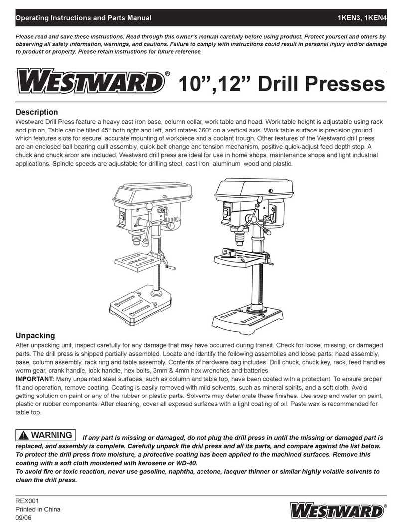
Hema PClamp N User manual

Operating instructions
PClamp N
PClamp ISO
PClamp E
PClamp_EN_2020_22012020 23.01.2020 15:39 Seite 1

PClamp
Operating manual
Information status: 1.01.2020, Version 4.1
Language of original version: German
Specifications subject to modification without prior notice. Errors excepted
No part of this documentation may be reprinted or published without prior consent issued in
writing by HEMA. RotoClamp, LinClamp and PClamp are developments by InnoTech Engineering
GmbH and are legally protected by trademarks and patents.
Contact
For further details, please contact:
HEMA Maschinen- und Apparateschutz GmbH
Am Klinggraben 2
63500 Seligenstadt
Germany
Phone: +49 (0)6182-773-0
Fax: +49 (0)6182-773-35
Web: www.hema-group.com
EN
2
Art-No 80-00-1030/EN 22012020
PClamp_EN_2020_22012020 23.01.2020 15:39 Seite 2

Operating instructions
Content
. . . . . . . . . . . . . . . . . . . . . . . . . . . . . . . . . . . . . . . . . . . . . . . . . . . . . . . . . . . .Page
1. Important information . . . . . . . . . . . . . . . . . . . . . . . . . . . . . . . . . . . . . . . . .4
2. General description . . . . . . . . . . . . . . . . . . . . . . . . . . . . . . . . . . . . . . . . . . .4
3 Model variants . . . . . . . . . . . . . . . . . . . . . . . . . . . . . . . . . . . . . . . . . . . . . . .5
4. Operating components and connections . . . . . . . . . . . . . . . . . . . . . . . . . . .6
5. Use . . . . . . . . . . . . . . . . . . . . . . . . . . . . . . . . . . . . . . . . . . . . . . . . . . . . . . . .6
6. Improper use/warnings . . . . . . . . . . . . . . . . . . . . . . . . . . . . . . . . . . . . . . . .7
7. Residual risks . . . . . . . . . . . . . . . . . . . . . . . . . . . . . . . . . . . . . . . . . . . . . . . .7
8. Warranty . . . . . . . . . . . . . . . . . . . . . . . . . . . . . . . . . . . . . . . . . . . . . . . . . . . .8
9. Transport/storage/intermediate storage . . . . . . . . . . . . . . . . . . . . . . . . . . .9
10. Type designation . . . . . . . . . . . . . . . . . . . . . . . . . . . . . . . . . . . . . . . . . . . . . .9
11. Assembly instructions . . . . . . . . . . . . . . . . . . . . . . . . . . . . . . . . . . . . . . . . .9
12. Installed state (example) . . . . . . . . . . . . . . . . . . . . . . . . . . . . . . . . . . . . . .10
13. Installing the PClamp . . . . . . . . . . . . . . . . . . . . . . . . . . . . . . . . . . . . . . . . .11
14. Starting up . . . . . . . . . . . . . . . . . . . . . . . . . . . . . . . . . . . . . . . . . . . . . . . . .13
15. Maintenance and care . . . . . . . . . . . . . . . . . . . . . . . . . . . . . . . . . . . . . . . .14
16. CE Marking . . . . . . . . . . . . . . . . . . . . . . . . . . . . . . . . . . . . . . . . . . . . . . . . .14
17. EG declaration of conformity . . . . . . . . . . . . . . . . . . . . . . . . . . . . . . . . . . .15
18. Causes of faults - solutions . . . . . . . . . . . . . . . . . . . . . . . . . . . . . . . . . . . .16
19. PClamp N - specification and drawing . . . . . . . . . . . . . . . . . . . . . . . . . . . .17
20. PClamp ISO - specification and drawing . . . . . . . . . . . . . . . . . . . . . . . . . .18
21. PClamp E - specification and drawing . . . . . . . . . . . . . . . . . . . . . . . . . . . .19
EN
3
Art-No 80-00-1030/EN 22012020
PClamp_EN_2020_22012020 23.01.2020 15:39 Seite 3

1. Important information
These operating instructions describe how to use the PClamp N, ISO, E components properly.
Warranty claims are valid only when these instructions have been observed.
It is therefore imperative that you please read these instructions before using the safety clamp
and/or brake to the end.
It is imperative that you observe the thresholds (e.g. for pressures, forces, torques, and
temperatures) and tolerance ranges for the round piston rods and clamping pairing
specified in these instructions.
Make sure that the supplied compressed air has been properly treated
Consider the environmental operating conditions.
Observe the rules and regulations issued by the professional associations and the
technical safety inspectorate TÜV, and the pertinent national, international, and European
terms and conditions.
Before installing for the first time, please remove all transport locks and guards like paper,
foil, etc. Each of these materials must be introduced to the legally prescribed disposal cycle
(recycling containers).
The product may be installed and commissioned only by qualified, specialised personnel in
accordance with these operating instructions.
Symbols used
Warning
Note
2. General description
All models in the PClamp, PClamp N, ISO and E series are round-rod clamping and
braking elements.
All PClamp products open pneumatically and generate their clamping force via a spring
accumulator.
The retaining force is exerted by the friction applied by the clamping sleeve, which is
pressed vertically against the contact surfaces on a round rod.
Disengaging: pressure is applied to the chamber between the spring diaphragms. The
diaphragm plates are elastically deformed and shortened in the radial direction. The
elastically pre-tensioned clamping sleeve increases its diameter to release the round rod.
!
Open
A1 =1 p
Compressed Air
PClamp
EN
4
PClamp_EN_2020_22012020 23.01.2020 15:39 Seite 4

Clamping: air is drawn out of the chamber between the spring diaphragms. The
diaphragms relax and reduce the clamping sleeve’s diameter. The clamping sleeve is
pressed against the round rod. In this way, longitudinal movements can be stopped and
held, rotating movements may only be held on systems that are at a standstill.
3. Model variants
The PClamp N, ISO, E components are available in different sizes. The sizes are derived from
the sizes of standard ISO/VDMA cylinders. Cylinders and the PClamp N, ISO components
possess identical footprints. The model variants differ in the following aspects:
number of clamping modules; depending on the type, up to four modules are possible
different clamping diameters, depending on the application
different base and cover plates, depending on the application
number and size of air connections
the operating pressure is generally 4 or 6 bars, other pressures are optionally available
on inquiry
Rod scraper, optional
optional without preparations for inductive proximity switch
housing material used
the PClamp N, ISO, E components are also possible in customised special sizes and with
other operating pressures
Close
A1 =0 p
PClamp N, one clamping modul
two clamping modules three clamping modules four clamping modules
PClamp ISO PClamp E
Operating instructions
EN
5
PClamp_EN_2020_22012020 23.01.2020 15:39 Seite 5

4. Controls and connections
Fastening options and connections:
Through hole (A) in the housing.
IMPORTANT! The fastening screws must be able to reliably take all loads that occur during
the application.
The control air connection for open and close (B) directly in the G 1/8 or M5 housing.
Optional venting connection (C) directly in the G 1/8 or M5 housing.
Optional preparation for inductive limit switch (D).
5. Use
The clamping elements of the PClamp series are primarily designed for braking and
holding piston rods on pneumatic cylinders and loads suspended from them. PClamps may
also be used for braking and holding other machine elements that make translational move-
ments and for holding machine elements with round cross-sections that make rotational
movements. This applies insofar as the scope of application – particularly the retaining
forces – specified for the clamping elements is observed. The direction of the introduction
of force or the axis of rotation of the effective torques is identical to the clamping sleeve's
central axis.
The switching times for all the controls and the response times by the PClamp N, ISO, E
components must be observed, the braking distances must be calculated and checked
during commissioning. The PClamp N, ISO, E components may only be used with the
specified operating pressure of 4 or 6 bars – depending on the type.
The functioning of all PClamps depends on the combination of the PClamp with the
clamping surface. The round rod's properties are therefore important factors. All PClamp
clamping elements have been optimised for the following conditions: round rod diameter
equal nominal diameter with a tolerance zone of h9 or better, round rod material
(manufacturer-dependent), e.g. C45, hard chromed, roughness Ra 0.4 - 0.8 µm.
When using the PClamp N, ISO, E components for braking, the braking force must be
dimensioned in accordance with the permissible braking distance. The force of the
weight must be added to the braking force in vertical applications.
A
A
A
A
D
C
B
!
PClamp
EN
6
PClamp_EN_2020_22012020 23.01.2020 15:39 Seite 6

6. Improper use / warning
Braking from already developed movements, of rotationally moved machine elements
is not permitted.
The retaining forces specified by HEMA can only be achieved under optimum conditions.
Fats, wear, corrosion, soiling, defects, etc. may result in changing braking/retaining forces
and moments.
The optional rod scrapers must be used to prevent fats or accumulations of greasy dirt
from negatively affecting performances.
The optional inductive limit switches have been designed solely for the purposes of
recognising the switching status and not for the purposes of carrying out function checks.
The PClamp N, ISO, E clamping and braking systems are not designed to secure suspended
loads when machines or machine parts are being manufactured, transported, assembled,
installed, commissioned, used, cleaned, subjected to troubleshooting, shut down,
disassembled or disposed of in personal danger areas without redundant safety systems.
PClamp N, ISO, E cannot be used as guides or as bearings for moving machine elements.
Shearing forces may result in reduced braking/retaining forces and torques, limit-switch
malfunctions and/or defects.
Deviations from the specified operating pressure may result in damage and/or cause the
system to fail. Higher pressures don't equate with greater retaining forces.
The braking effect or build-up of force may be delayed if the system has not been in use
or has not been activated for a long time.
The screwed connections must be able to absorb the maximum retaining forces during
the application
The limit switches' signals may cause the control to malfunction.
7. Residual risks
The PClamp N, ISO, E clamping and braking systems are not fitted with a second safety
circuit. When the system is actuated intentionally or by accident, the clamp opens and there-
fore the retaining force is no longer transferred to the round rod so that the force or mass to
be secured will no longer be held. As a consequence, during all operating modes and life-
cycle phases without a redundant system there are mechanical dangers. Additional residual
risks of crushing, cutting, shearing, abrasion, puncturing, accelerated components exist as a
result of:
unsecured connected structures, disruptions in the pneumatic air supply (e.g. pressure
fluctuations)
human error (e. g. stress, fatigue, »convenient shortcuts«)
failure to observe the information and warning signs
wrong use of the PClamp (see Section 6.)
impacts, abrasion, cutting as a consequence of inadequate compressed air connections
or loose compressed air lines or fastening screws
wrong switching procedures as a result of wrong signals from the limit switches
unintentionally fast-moving round or piston rods
7
!
Operating instructions
EN
7
PClamp_EN_2020_22012020 23.01.2020 15:39 Seite 7

8. Warranty
Valid for the following conditions of use:
The clamping and braking elements are used properly only when they are used in full
compliance with the technical specifications. Any other use will exempt HEMA Maschinen-
und Apparateschutz GmbH from providing any other services.
Ambient temperature min 10°C and max 45°C
Pneumatic operating pressure 4 or 6 bars, tolerance: ± 5%
Dried, filtered and oil-free air (particles: Class 4, condensate: Class 4, oil content: Class 3)
The warranty is valid for 12 months following delivery; however, but not in excess of
1,000,000 (one million) clamping cycles, without braking clamping. When submitting a
warranty claim, the customer must present suitable verification of the actual number of
clampings. No warranty can be assumed for braking clampings due to indefinable factors
that affect the components.
Installation, conversion, maintenance and repairs: observe the installation instructions
and use the necessary equipment along with the original accessories. The respectively
valid safety and installation instructions must be observed during all work on the
clamping and braking elements.
Use the supplied transport lock when the component has been dismounted. All PClamps
may only be clamped when an appropriate transport lock or round rod is located inside
the clamping sleeve.
Removing, dismantling or machining the PClamp by the customer without prior consent
issued in writing by HEMA reduces the operating safety and renders the warranty void.
The clamping sleeve's interior size has been produced to an exact value at the factory. The
largest possible retention force results from the smallest radial clearance between the
clamping sleeve and round piston rod.
The design peculiar to all PClamps requires that the tolerance range between the round
piston rod and clamp lie within the thresholds defined by the application. Care must in
particular be taken that the round rod is completely free when the clamp is open.
A friction force of around 2% of the nominal retaining force and friction by the optional rod
scrapers is normal.
When exposed to fat (piston rod's lubrication condition), the clamping systems' retention
forces may in certain circumstances be considerably reduced resulting in longer braking
distances. The optional rod scrapers must be used to prevent fats or fatty accumulations of
dirt from negatively affecting performances
No NBR-incompatible media or media that facilitates corrosion
Corrosion may occur as a result of the material. Any warranty claims made on this basis
will not be recognised.
PClamp
EN
8
PClamp_EN_2020_22012020 23.01.2020 15:39 Seite 8

9. Transport, stporage, intermediate storage
Only transport the clamping elements in their relaxed state
The clamping elements should be placed in storage or interim storage in the preserved
state and in the packaging selected by HEMA.
Only store and transport the clamping elements with the supplied transport lock.
10. Type designation
The engraved type designation and serial number serve to clearly identify and track the
clamping element. It is unique for every clamping element and therefore absolutely
essential for tracking and chasing purposes. So never obliterate the engraving; the
engraving must be legible at all times. Removing or obliterating the type designation
renders all warranty claims void. The engraving describes the type and size.
The engraving can be found on the intermediate panel under the air and sensor
connections on the PClamp N and ISO type clamps; the engraving can be found on the
front next to the air connection on E type clamps.
11. Installation notes
Check that the type designation engraved on the PClamp agrees with the PClamp you want
to install
PClamps cannot be fitted if they are not pressurised as they can only be opened under
pressure.
Make sure that all contact surfaces between the PClamp and installation surface on the
connecting structures are clean and plane.
Handle the PClamp so that it cannot sustain damage. This will reduce the operating
safety and render the warranty void.
Make sure that the installation is free of torsion and that the permissible loads set out
in in the terms of delivery and the operating instructions are fulfilled.
The PClamp automatically centres itself on the round rod. This requires that the round
rod's positioning is sufficiently precise and stiff.
Screws of Property Class 8.8 or higher must be used to secure the PClamps. Tighten
the screws with the recommended tightening torque. Use a screw locking product,
e. g. Loctite. Recommended tightening torques:
PClamp N and ISO Size 63: 8 Nm Size 80: 15 Nm Size 125: 35 Nm
PClamp E Size 63: 3 Nm Size 80: 6 Nm Size 125: 12 Nm
Operating instructions
EN
9
PClamp_EN_2020_22012020 23.01.2020 15:39 Seite 9

Important! In order to allow the specified retaining forces to be transferred in the best
way possible, the clamping sleeve's inside surface and the round rod's surface must be
thoroughly cleaned and any grease removed before installation.
If desired, limit switches possessing an M8 x 1 thread may be fitted. Select limit switches
with a low switching distance and low hysteresis (e.g. Sn 1.5 mm, hysteresis <10%).
Minimum screw-in depth for Size 63 = 19 mm, Size 80 = 22 mm, Size 125 = 27 mm.
The limit switches are exclusively for monitoring the condition, they are not suitable
for use as safety-relevant control systems.
The customer must implement suitable additional safety measures to prevent
malfunctioning or risks.
Important! Connections with high flow resistances (long, thin, tight radii, bends) may
affect response times.
High speed or fast ventilation valves can considerably reduce the response times of the
PClamp!
Never fit two or more PClamps above each other; HEMA supplies special solutions for
such requirements.
12. Installed state (sample)
!
!
!
!
PClamp
EN
10
PClamp_EN_2020_22012020 23.01.2020 15:39 Seite 10

13. Installing the PClampp
Carry out installation in the following steps:
Open the PClamp with compressed air
Position
Venting and alignment
Screw tight
Optional, fitting and adjusting inductive limit switches.
The individual steps in detail:
Screw in an appropriate pneumatic connection:
Size 63 M5
Size 80 G1/8
Size 125 G1/8
Then connect with air hose
Apply nominal pressure to PClamp and remove the transport lock.
Position the PClamp on the round rod, screw in the fastening screws loosely, do not
tighten yet! See the following steps.
Operating instructions
EN
11
PClamp_EN_2020_22012020 23.01.2020 15:39 Seite 11

Vent the PClamp. The PClamp will centre itself automatically on the round rod.
Here, the PClamp should be as close to its final position as possible but sufficiently free
so that it can align itself.
Tighten the fastening screws crosswise over several circuits up to the defined
tightening torque, please also refer to the installation instruction on Page 10. Open and
close the PClamp several times between each step. The screws may only be tightened
when the PClamp is closed and thus centred
Do not exceed the recommended tightening torque (see Page 10), use bolt adhesive.
Check the screw connections in regard to the occurring loads. HEMA assumes no
warranty for this.
Apply nominal pressure to the PClamp and check for ease of movement. If necessary,
repeat the installation process.
PClamp N
EN
12
PClamp_EN_2020_22012020 23.01.2020 15:39 Seite 12

Finally, install and set the limit switches for condition monitoring. To this end, change
the control to the different respective switching statuses and choose the screw-in depth
such that the one monitoring diode lights up in sequence with the other.
The switch close to the air connection must be activated in the clamped condition, the
switch furthest away from the air connection must activated when open. Secure with
the counter nut. Check the correct setting.
Guide values for screw-in depth: PClamp 63: 19 mm, PClamp 80: 22 mm, PClamp 125: 27 mm.
Do not screw in the limit switch significantly deeper; stop when resistance is felt, continuing
to screw the component in may result in defects being caused.
On types with ventilation connection: screw in a corresponding pneumatic connection:
Size 63 M5, Sizes 80 and 125: G1/8, attach connection to air hose; position the hose so
that it ends at a clean and dry place. This will prevent dirt, moisture and foreign bodies
from being sucked in.
14. Commisioning
Install the control valve close to the clamping element, connect with appropriate hose.
Important! Connections with high flow resistances (long, thin, tight radii, bends) may
affect response times.
Once it has been installed properly, check the PClamp for operational readiness.
Check ease of movement by manually moving the linear unit.
The clamping process must be checked; it may no longer be possible to manually move
the round rod.
All pneumatic connections must be checked for leaks after pressure has been applied to
the PClamp.
Take precautions for the event that the retaining forces are insufficient due to errors.
Throttle movement and set stop buffers to a high load.
Check that all fastening bolts have been tightened using the specified tightening torque.
Owing to the paired fits configured for the PClamp and the round rod at the factory,
readjustments are not required after proper installation.
Start a test run while observing the applicable regulations and execute 500 test cycles.
B10d values: PClamp, all types 2,000,000 cycles
Operating instructions
EN
13
PClamp_EN_2020_22012020 23.01.2020 15:39 Seite 13

15. Maintenance and care
Before installation, clean the round rod's and the brake/clamp linings' contact surfaces
with a soft cloth. Approved cleaning agents are all media that do not attack the
materials (recommendation: Weicon: »S« spray cleaner).
Check the clamping surfaces for wear and material abrasion.
Regularly check the function, the PClamp must be regularly exposed to loads.
Otherwise the braking/clamping effect may become delayed or reduced. Processes that
negatively impact the effect must be expected in the event of very long downtimes.
16. CE marking
In the delivered state, the PClamp N, ISO, E clamping elements fulfil the requirements
under the Machinery Directive 2006/42/EC and are marked with the CE symbol.
PClamp
EN
14
PClamp_EN_2020_22012020 23.01.2020 15:39 Seite 14

17. EC declaration of conformity
In accordance with the EC Machinery Directive 2006/42/EC of 17 May 2006, Annex II A
We hereby declare that the design and type of the structurally identical safety components
named in the following comply in their conception and build and the version we market with the
fundamental safety and health requirements in the EC Machinery Directive 2006/42/EC. This
declaration becomes void when any change is made without our consent to the safety components.
Manufacturer HEMA Maschinen- und Apparateschutz GmbH
Am Klinggraben 2, 63500 Seligenstadt, Germany
Phone: +49(0)6182/773-0, Fax: +49(0)6182/773-35
www.hema-group.com
Description of the machine
Function: Clamping of stationary shafts and axles exposed to rotational loads
Braking and clamping of round piston rods making linear movements.
Type/model: PClamp N, ISO, E
Applied harmonized standards, in particular:
DIN EN ISO 12100: 2011-03
Safety of machinery - General principles of design - Risk assessment and risk reduction
German version EN ISO 20100: 20100
DIN EN ISO 12100: 2013-08
Safety of machinery - General principles of design - Risk assessment and risk reduction,
Corrigendum to DIN EN ISO 20100: 2011-03
German version EN ISO 20100: 20100
DIN EN ISO 13849-1: 2016-06
Safety-related parts of control systems, Part 1: General principles of design
German Version he Fassung EN ISO 13849-1: 2015
DIN EN ISO 13849-2: 2013-02: Safety-related parts of control systems,
Part 2: Validation
German Version EN ISO 13849-1: 2015
Other technical standards and specifications applied:
DIN ISO 8573-1 2010-04 Compressed air - Part 1: Impurities and purity classes
HEMA Maschinen- und Apparateschutz GmbH
Steffen Walter Philipp Sendelbach
Managing Director CE authorized person
Am Klinggraben 2, 63500 Seligenstadt
Seligenstadt, 1 Januar 2020
Operating instructions
EN
15
PClamp_EN_2020_22012020 23.01.2020 15:39 Seite 15

18. Causes of faults - solutions
PClamp
EN
16
Malfunction Possible cause Remedy
Retaining force
does not
correspond to
specifications
Air pressure at the pneumatic cylinders too
high (more than 4 or 6 bars)
Call HEMA services
Rod and clamping sleeve soiled with lubricant
or fats
Clean rod with suitable cleaner, remove any
soiling, check material pairing with HEMA
services
Round rod/shaft or round guide to small Select round rod/shaft with matching diameter,
contact HEMA services
Clamp and screw-on surfaces not sufficiently
parallel
Ensure that they are parallel, take constructional
precautions, compensate differences with metal
foil
Tolerance dimensions between PClamp and
shaft deviate from specifications
Adhere to tolerances as specified by HEMA,
check tolerance and roundness
Tightening torques and correct force transfer
through screwed connection not perfect
Check tightening sequence of the connecting
screws and tightening torque
PClamp's life span exceeded Call HEMA services
Clamp does not
open properly
Diaphragm error Check the PClamp's functioning; check it for leaks,
contact HEMA services
Round rod/shaft or round guide to large Select round rod/shaft with matching diameter,
contact HEMA services
Clamp and screw-on surfaces not sufficiently
parallel
Ensure that they are parallel, take constructional
precautions, compensate differences with metal
foil
Pressure insufficient Increase pressure up to max nominal pressure
Alignment not precisely executed during
installation
Check for sufficient clearance, check installation
steps again
Storage and transport temperature outside of
specifications
Temperatures under 10°C can affect the rubber
diaphragm. This then becomes hard and un-
susceptible, and may leak temporarily
Response times
too long
Air supply throttled too much Valve too small, maintenance unit too small,
supply line too long, too thin, not free or bent
Venting insufficient Check and ensure venting
Unfavourable compressed-air circuit Avoid long and thin hoses, tight radii, etc.; high
flow resistances produce long response times,
call HEMA services
Storage and transport temperature outside of
specifications
Temperatures under 10°C can affect the rubber
diaphragm. This then becomes hard and unsus-
ceptible, and may leak temporarily
Loud air and
purging noise
Diaphragm error Check the PClamp's functioning; checkit for leaks,
contact HEMA services
Storage and transport temperature outside of
specifications
Temperatures under 10°C can affect the rubber
diaphragm. This then becomes hard and unsus-
ceptible, and may leak temporarily
Screw connections on connecting parts leaking Tighten screw connection, change sea
PClamp's life span exceeded Call HEMA services
PClamp_EN_2020_22012020 23.01.2020 15:39 Seite 16

M 8 x 1
(for inductive
sensors)
Air
connection*
* Number and size on request
optional
rod wiper
DA
A
Ø C
A
B
E* E*
B
Subject to modifications. Only the written order confirmation is valid.
19. PClamp N
Specifications and drawing
Profile A-A
Operating instructions
EN
17
Size
A B C D E Air
connec-
tion
Holding
force
Version
4 bar
Holding
force
Version
6 bar
Holding
torque
Version
4 bar
Holding
torque
Version
6 bar
Stan-
dard
rod
Mass
max.
Unit [mm] [mm] [mm] [mm] [mm] [Nm] [Nm] [Nm] [Nm] [mm] [kg]
PC 63-20-1 N 75 56,5 8,5 41,5 2,1 M5 1400 2000 15 20 20 0,7
PC 63-20-2 N 75 56,5 8,5 59,5 2,1 M5 2520 3600 25 35 20 1,13
PC 63-20-3 N 75 56,5 8,5 77,5 2,1 M5 3780 5400 35 50 20 1,56
PC 80-25-1 N 96 72 10,5 43,5 2,2 G
1/8"
2100 3000 25 35 25 1,3
PC 80-25-2 N 96 72 10,5 63,5 2,2 G
1/8"
3780 5400 40 60 25 2,2
PC 80-25-3 N 96 72 10,5 83,5 2,2 G
1/8"
5670 8100 65 95 25 3,1
PC 80-25-4 N 96 72 10,5 83,5 2,2 G
1/8"
7560 10800 85 125 25 3,1
PC 125-40-1 N 145 110 13 51,6 3 G
1/8"
7000 10000 140 200 40 3,65
PC 125-40-2 N 145 110 13 75,2 3 G
1/8"
12600 18000 250 360 40 5,85
PC 125-40-3 N 145 110 13 98,8 3 G
1/8"
18900 27000 375 540 40 8,05
PC 125-40-4 N 145 110 13 122,4 3 G
1/8"
25200 36000 500 720 40 10,25
PClamp_EN_2020_22012020 23.01.2020 15:39 Seite 17

M 8x1
(for inductive
sensors
G 1/8
Air connection
optional
rod wiper
A
E
Profile A-A
A
A
B
D
Ø C
B
Subject to modifications. Only the written order confirmation is valid.
20.PClamp ISO
Specifications and drawing
PClamp
EN
18
Size
A B C D E Air
connec-
tion
Holding
force
Version
4 bar
Holding
force
Version
6 bar
Holding
torque
Version
4 bar
Holding
torque
Version
6 bar
Stan-
dard
rod
Mass
max.
Unit [mm] [mm] [mm] [mm] [mm] [Nm] [Nm] [Nm] [Nm] [mm] [kg]
PC 63-20-1 ISO 75 56,5 8,5 69,5 2,1 M5 1400 2000 15 20 20 1
PC 63-20-2 ISO 75 56,5 8,5 87,5 2,1 M5 2520 3600 25 35 20 1,43
PC 63-20-3 ISO 75 56,5 8,5 105,5 2,1 M5 3780 5400 35 50 20 1,86
PC 80-25-1 ISO 96 72 10,5 67,5 2,2 G
1/8"
2100 3000 25 35 25 1,8
PC 80-25-2 ISO 96 72 10,5 87,5 2,2 G
1/8"
3780 5400 40 60 25 2,7
PC 80-25-3 ISO 96 72 10,5 107,5 2,2 G
1/8"
5670 8100 65 95 25 5,6
PC 125-40-1 ISO 145 110 13 95,6 3 G
1/8"
7000 10000 140 200 40 5,65
PC 125-40-2 ISO 145 110 13 119,2 3 G
1/8"
12600 18000 250 360 40 7,85
PC 125-40-3 ISO 145 110 13 142,8 3 G
1/8"
18900 27000 375 540 40 10,05
PC 125-40-4 ISO 145 110 13 166,4 3 G
1/8"
25200 36000 500 720 40 12,25
PClamp_EN_2020_22012020 23.01.2020 15:39 Seite 18

21. PClamp E
Specifications and drawing
G 1/8 - 6 deep
air connection
D
Ø A
45°
49
E
LK Ø B
C DIN 74 (4x)
fastening hole
Subject to modifications. Only the written order confirmation is valid.
optional
rod wiper
Operating instructions
EN
19
Size
A B C D E Air
connecti-
on
Holding
force
Version
4 bar
Holding
force
Version
6 bar
Holding
torque
Version
4 bar
Holding
torque
Version
6 bar
Stan-
dard
rod
Mass
max.
Unit [mm] [mm] [mm] [mm] [Nm] [Nm] [Nm] [Nm] [mm] [kg]
PC 63-20 E 92 80 M5 28 2,1 G
1/8"
700 1000 7 10 20 1,15
PC 80-25 E 118 118 M6 30 2,14 G
1/8"
1050 1500 12 17 25 2,1
PC 125-40 E 168 152 M6 34 3 G
1/8"
3500 5000 70 100 40 4,9
PClamp_EN_2020_22012020 23.01.2020 15:39 Seite 19

PClamp
PClamp_EN_2020_22012020 23.01.2020 15:39 Seite 20
This manual suits for next models
2
Table of contents
