HeMaTech 3925-0050 User manual
leak test flow test volume test test systems test machines
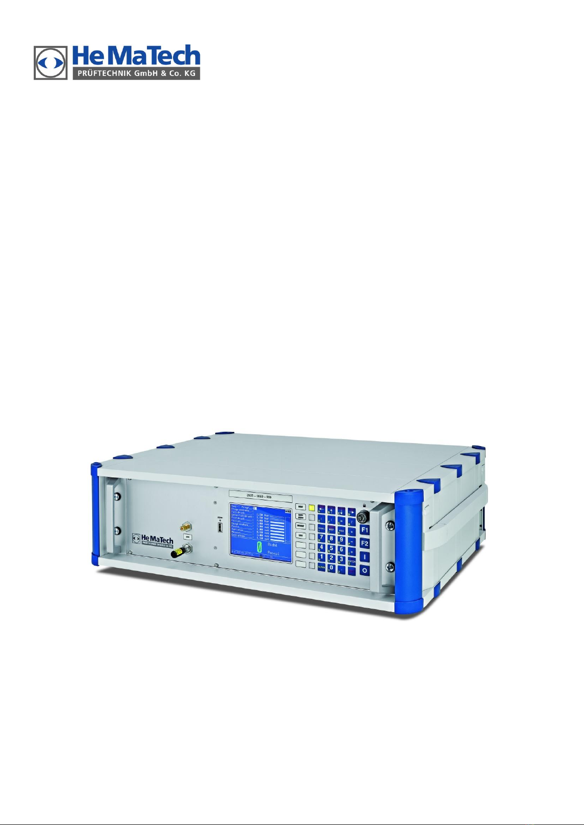
Leak Tester 3925 –0060
Operating Instructions
EN 3925-0060 V207-00 MANUAL R03.doc
Please read these instructions, before installing, starting up, storing or handling this device.

Any trademarks referred to in this manual are the
sole property of the corresponding owner.
HeMaTech Prüftechnik GmbH & Co. KG
Siemensstrasse 7
DE-71409 Schwaikheim
Phone +49 (0)71 95/13 69 0
Fax +49 (0)71 95/13 69 29
Internet http://www.hematech.de
© 2010 All rights reserved
Edition 07/2010
EN 3925-0050 V205-00 MANUAL R01.doc

Contents
Leak Tester 3925 –0060................................................... 1
Operating Instructions........................................................ 1
Introduction ...................................................................... 7
Concerning these operating instructions .................................................7
Intended use .......................................................................................8
Warranty.............................................................................................9
Structure of the manual ......................................................................10
Safety measures .............................................................. 12
Safety notes....................................................................................... 12
Symbols used .................................................................................... 14
Product description.......................................................... 15
The differential pressure method.......................................................... 15
Performance characteristics.................................................................18
Design and working principle ..............................................................19
Scope of delivery ...............................................................................20
View of device ...................................................................................21
Control elements ...............................................................................23
Installation and start-up ................................................... 25
Connecting peripheral equipment........................................................25
Switching the device ON and OFF....................................................... 28
Initializing....................................................................... 29
The display ..................................................................... 30
Working with the program ..................................................................31
Using the write protection switch..........................................................31
Command reference........................................................ 32
Program structure ..............................................................................32
Menu 1. AUTOMATIC........................................................................33
Sequencer ........................................................................................... 35
Automatic mode without leak simulation ................................................. 36
Menu 2. MANUAL .............................................................................37
1. Test ................................................................................................ 37
1.1 Determination of a reference record ................................................. 39
1.1 Sequencer ..................................................................................... 40
2. Pressurize (Flooding)......................................................................... 42
Menu 3. SETUP ................................................................................. 44
1. Set parameter (Test program)............................................................. 44
1.1 Printout PARAMETER....................................................................... 51
1.2 Copying an existing test program ..................................................... 53
2. Date & Time. ................................................................................... 54
3. Serial ports ...................................................................................... 55
3.1 Output format Profibus.................................................................... 62

3.2 Output format Profinet....................................................................67
4. Sequencer........................................................................................77
4.1 Printout SEQUENCER PARAMETER....................................................79
5. Adjusting the filling/testing pressure manually (option 0050-04).............81
6. Adjusting the vacuum manually (option 0050-01).................................83
Menu 4. DELETE ............................................................................... 84
Menu 5. PRINT MENU....................................................................... 85
1. View Program Status..........................................................................85
2. Data Collection ................................................................................86
2.1 Print Data Collection .......................................................................87
3. Operating data.................................................................................88
4. Counter...........................................................................................88
5. Backup ............................................................................................89
6. Error counter status ...........................................................................90
7. Record.............................................................................................91
8. Record Reverence .............................................................................93
Menu 6. SETTINGS ........................................................................... 95
1. Display ............................................................................................95
2. System parameters ............................................................................97
3. Pressure control ................................................................................99
4. System status ....................................................................................101
5. Options ...........................................................................................102
Testing and Setup.......................................................... 104
Testing the leak tester .......................................................................104
Setting up the device for specimen .....................................................106
Leak simulation (option) ....................................................................107
Maintenance................................................................. 108
Maintenance contract .......................................................................108
Maintenance plan ............................................................................108
Errors, Causes and Remedy ...............................................................109
Acknowledging error messages ..........................................................109
Trouble Shooting Chart.....................................................................110
Signal Exchange with Machine Control............................ 114
Automatic operation .........................................................................115
In semi-automatic operation ..............................................................118
Sample printouts ........................................................... 122
Protocol printout ..............................................................................122
Program parameters.........................................................................123
Result memory .................................................................................124
System parameters............................................................................125
Appendix...................................................................... 127
Plug assignment...............................................................................128
Pneumatic diagram (vacuum device) ..................................................128
Pneumatic diagram (overpressure device)............................................130
Technical Data.................................................................................130

Table of contents
Popular Test Equipment manuals by other brands


Redtech
Redtech TRAILERteck T05 user manual

Venmar
Venmar AVS Constructo 1.0 HRV user guide

Test Instrument Solutions
Test Instrument Solutions SafetyPAT operating manual

Hanna Instruments
Hanna Instruments HI 38078 instruction manual

Kistler
Kistler 5495C Series instruction manual

Waygate Technologies
Waygate Technologies DM5E Basic quick start guide

StoneL
StoneL DeviceNet CK464002A manual

Seica
Seica RAPID 220 Site preparation guide

Kingfisher
Kingfisher KI7400 Series Training manual

Kurth Electronic
Kurth Electronic CCTS-03 operating manual

SMART
SMART KANAAD SBT XTREME 3G Series user manual

Agilent Technologies
Agilent Technologies BERT Serial Getting started