Hendi 979983 User manual

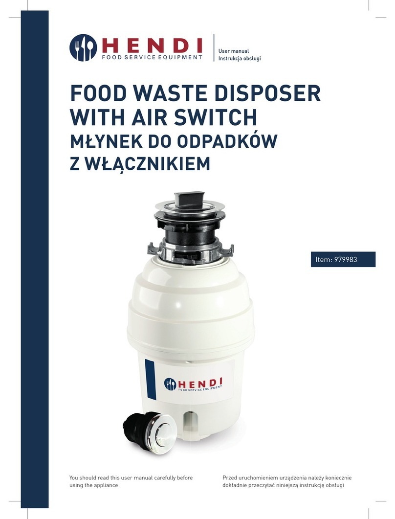
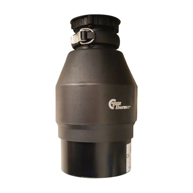
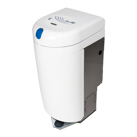
Food waste disposer
with air switch
Młynek do odpadów z włącznikiem
979983
User manual | Instrukcja obsługi
You should read this user manual carefully before
using the appliance.
Przed uruchomieniem urządzenia należy koniecznie
dokładnie przeczytać niniejszą instrukcję obsługi.

Keep this manual with the appliance.
Zachowaj instrukcję urządzenia.
For indoor use only.
Do użytku wewnątrz pomieszczeń.
CONTENTS
IMPORTANT SAFETY INSTRUCTIONS ...................................3
1. REMOVAL OF OLD UNIT ........................................................4
2. DISHWASHER CONNECTION.................................................5
3. INSTALLATION OF MOUNTING ASSEMBLY...........................5
4. ELECTRICAL CONNECTIONS ................................................7
5. ATTACHING DISCHARGE ELBOW..........................................8
6. CONNECTING DISPOSER TO MOUNT ASSEMBLY.................8
7. OPERATING INSTRUCTIONS .................................................9
8. AIR SWITCH INSTALLATIONS..............................................10
9. TROUBLESHOOTING ...........................................................10
10. CLEANING AND MAINTENANCE......................................... 11
11. DISCARDING & ENVIRONMENT ..........................................11
12. WARRANTY..........................................................................12

3
EN
Dear Customer,
Thank you for purchasing this Hendi appliance. Before using the appliance for the first time, please read
this manual carefully, paying particular attention to the safety regulations outlined below.
SEE INSERT FOR SPECIFIC INFORMATION ABOUT YOUR NEW DISPOSER
NOTE: This Food Waste Disposer has been designed to operate with your appropriate household
current exclusively. Using any other voltage or Hz adversely affects performance.
IMPORTANT: Read all instructions thoroughly. Keep this guide for future reference.
CAUTION:
Be sure to review SAFETY INSTRUCTIONS FIRST PERTAINING TO A RISK OF FIRE, ELECTRICAL
SHOCK OR INJURY TO PERSONS before using disposer.
RECORD IMPORTANT DISPOSER INFORMATION HERE
Model Number* Serial Number*
* Above information appears on the label affixed to bottom of the disposer. For your convenience, write
down the model and serial numbers prior to installation.
IMPORTANT SAFETY INSTRUCTIONS
INSTRUCTIONS PERTAINING TO A RISK OF FIRE, ELECTRIC SHOCK OR INJURY TO
PERSONS. SAVE THESE INSTRUCTIONS.
WARNING – When using electrical appliances, basic precautions should always
be followed, including the following:
• Read all instructions before using the appliance.
• To reduce the risk of injury, close supervision is necessary when an appliance is
used near children.
• Do not put fingers or hands into a waste disposer.
• Turn the power switch to the off position before attempting to clear a jam or re-
move an object from the disposer.
• When attempting to loosen a jam in a waste disposer, use a long wooden object
such as a wooden spoon or the wooden handle of a broom or mop.
• When attempting to remove objects from a waste disposer use long-handled
tongs or pliers. If the disposer is magnetically actuated, non-magnetic tools
should

4
EN
• To reduce the risk of injury by materials that may be expelled by a waste dispos-
er,
do not put the following into a disposer: clam or oyster shells; caustic drain
cleaners or similar products; glass, china or plastic; large whole bones; metal,
such as bottle caps, tin cans, aluminum foil or utensils; hot grease or other hot
liquids; whole cornhusks.
• When not operating a disposer, leave the stopper in place to reduce the risk of
objects falling into the disposer.
• DO NOT operate disposer unless splash guard is in place.
• For proper grounding instructions see the ELECTRICAL CONNECTION portion of
this manual.
1. REMOVAL OF OLD UNIT
TYPICAL INSTRUCTIONS, YOUR MODEL MAY VARY.
Before starting this step, turn off electrical power
at the circuit breaker or fuse box. If your old mount
is the same as the mount on your new disposer,
just reverse the assembly instructions found in
section 3. If your new mount system is different,
follow these instructions:
• Use a pipe wrench to disconnect drain line where
it attaches to disposer discharge tube (see 1A).
• Remove disposer from sink flange by turning
mount ring to the left clockwise (see 1B). If you
are unable to turn the mount ring, tap on one
of the extensions from the ring with a hammer.
Some mounting systems have tubular exten-
sions. Inserting a screwdriver into one tube will
provide additional leverage for turning the mount
ring (see 1B). Some disposers may require the
removal or loosening of nuts from the mount
screws (see 1C). Some disposers may require
the removal of a clamp.
CAUTION: Be sure to support the disposer while
performing this step or it may fall when the
mounting ring is disconnected from the mounting
assembly. If your disposer is hard wired (metal
shielded cable not utilizing a wall plug), complete
steps C and D. If you utilize a plugin cord, go on
to step E.
• When disposer is removed, turn up side down
and remove electrical cover plate (see 1D).
• Use screwdriver to remove green ground wire.
Remove wire nuts from black and white power
wires and separate disposer wires from power
cable wires. Loosen screws on cable clamp and
separate cable from disposer.
• To remove remaining mount system from the
sink, loosen mount screws, push mount ring up.
Under it is the snap ring. Use screwdriver to pop
off ring (see 1E). Remove mount ring, protector
ring and gasket from sink flange. Some mounts
will require the unscrewing of a large ring hold-
ing the sink flange in place. Pull sink flange up
through sink and clean off old putty from sink.
IMPORTANT: Unless you have a new home, this is
a good time to clean out the trap and drain lines
by running a drain auger or plumber’s snake be-
fore installing your new disposer.
5
EN
2. DISHWASHER CONNECTION
If you are utilizing a dishwasher, complete the fol-
lowing procedure. If dishwasher is not to be con-
nected go on to section 3.
A.
Using a blunt instrument (steel punch or wooden
dowel), knock out entire plug (see 2A). Do not use
a screwdriver or sharp instrument. When knock-
out plug falls into disposer, you may remove it or
simply grind it up when the disposer is used. This
will not damage the disposer in any way, but may
take some time to grind, over the course of sev-
eral uses. Go to Section 3.
B.Connect dishwasher hose using hose clamp. If
hose size is different, you will need a Dishwasher
Connector Kit (see 2B). Make sure all plumbing
connections are tight and in accordance with all
plumbing codes and ordinances. Run water and
check for leaks.
3. INSTALLATION OF MOUNTING ASSEMBLY
READ COMPLETELY BEFORE STARTING
NOTE: Pay close attention to the order of mount
assembly parts, as they have been correctly as-
sembled by the factory. Also, reference the cush-
ion mount detail in illustration 3J below for the
proper orientation of the cushion mount.
NOTE: Try practicing this assembly before you get
under the sink to get the “feel” of how the parts
fit together.
A.Disassemble mount assembly from disposer by
turning mount ring to the left (clockwise) and re-
move.
B.Raise mount ring toward top of sink flange.
Remove cushion mount. Remove mount ring.
You may want to practice installing the cushion
mount at this point before you are under the sink.
See paragraph H. Also see the “Important No-
tice: Cushion Mount Detail.”
C.Unscrew support ring from sink flange and re-
move fiber gasket. You are now left with sink
flange and rubber gasket.
D.The rubber gasket is used instead of plumbers
putty with stainless steel sinks. Other sinks will
require putty.
E.If no putty is used, insert sink flange through
rubber gasket into sink opening. Do not rotate
sink flange once it is seated.
F. If you use putty instead of the gasket, form a ring
around underside of sink flange. Insert flange
into sink opening, press down hard to squeeze
out excess putty. From under sink, trim off excess

6
EN
putty flush with bottom edge of sink opening.
G.From underneath sink, slip fiber gasket onto
exposed sink flange. With arrows pointing up,
screw support ring onto the sink flange, hand
tighten until the sink flange will not move (see
3F). At this point you may want to insert stopper
in sink and fill with water to check sink flange
seal and insure there are no leaks.
H. Place mount ring over sink flange and hold in
place while installing cushion mount (large side
down) so the groove on the inside of cushion
mount fits over lip on sink flange, similar to put-
ting the lid on a plastic container (see 3G, 3H & 3J).
Please read important notice below.
IMPORTANT NOTICE: CUSHION MOUNT DETAIL
When the cushion mount is installed correctly,
the lip of the sink flange fits into the groove on
the inside of the cushion mount and mount ring
can be pulled downward over cushion mount and
will be free to rotate. The bottom bead of the
cushion mount acts as a gasket between the bot-
tom of the sink flange and the top of the disposer.
See illustration 3J.

7
EN
4. ELECTRICAL CONNECTIONS
Now is the time to record the SERIAL NUMBER (located on the bottom of the disposer) onto the warranty card.
IF YOU ARE NOT FAMILIAR WITH ELECTRICAL POWER AND PROCEDURES, CALL A QUALIFIED ELECTRICIAN
WARNING: IMPROPER CONNECTION OF THE EQUIPMENT-GROUNDING CONDUCTOR
CAN RESULT IN A RISK OF ELECTRIC SHOCK. CHECK WITH A QUALIFIED ELECTRI-
CIAN OR SERVICEMAN IF YOU ARE IN DOUBT AS TO WHETHER THE APPLIANCE IS
PROPERLY GROUNDED. DO NOT MODIFY THE PLUG PROVIDED WITH THE APPLI-
ANCE IF IT WILL NOT FIT THE OUTLET, HAVE A PROPER OUTLET INSTALLED BY
A QUALIFIED ELECTRICIAN.
4.1. GROUNDING INSTRUCTIONS
FOR WASTE DISPOSERS EQUIPPED WITH A GROUND-
ED PLUG-IN POWER CORD.
This appliance must be grounded. In the event of
a malfunction or breakdown, grounding provides
a path of least resistance for electric current to re-
duce the risk of electric shock. This appliance is
equipped with a cord having an equipment-ground-
ing conductor and a grounding plug. The plug must
be plugged into an appropriate outlet that is prop-
erly installed and grounded in accordance with all
local codes and ordinances.
FOR WASTE DISPOSERS NOT EQUIPPED WITH
A GROUNDED PLUG-IN POWER CORD.
This appliance must be grounded. In the event of
malfunction or breakdown, grounding provides
a path of least resistance for electric current to re-
duce the risk of electric shock. The power cord (to
be installed) must have an equipment-grounding
conductor and a grounding plug. The plug must be
plugged into an appropriate outlet that is properly
installed and grounded in accordance with all local
codes and ordinances.Disconnect electric power to
disposer circuit before installation. Turn the circuit
breaker to the OFF position or remove the fuse.

8
EN
5. ATTACHING DISCHARGE ELBOW
A. Connect waste elbow to the disposer (see 5A),
proceed to step 6 and then connect bottom of the
elbow by tightening the slip nut (see 5B).
B. If you are connecting to a dishwasher, return to
section 2B. If not, make sure all plumbing connec-
tions are tight and in accordance with all plumbing
codes and ordinances. Run water and check for
leaks.
6. CONNECTING DISPOSER TO MOUNT ASSEMBLY
A. Line up disposer under mounting assembly.
Guide hopper projections into mount ring slots.
Turn mount ring about 1/4” to right so that
disposer is temporarily supported (see 6C).
B.Turn mount ring and disposer until disposer el-
bow lines up with trap (see 6D).
C. Turn mount ring to the right (counter-clockwise)
until it locks up tight. Tap the mount ring ears
with a hammer until the lock position is achie-
ved. Hopper projections must be to extreme left
of mounting slots (see 6E).
D.If mount ring is hard to turn, you may add a small
amount of petroleum jelly or liquid soap to hop-
per projections. Run water and check for leaks.

9
EN
7. OPERATING INSTRUCTIONS
The Anti-Jam Swivel Impellers make a clicking sound as they swing into place. This indicates normal op-
eration.
A. Remove sink stopper. Turn on a medium flow of
cold water.
B.Turn switch to ON position; your motor is turning
at full speed and ready to use.
C.
Scrape in food waste. Down the drain go table
scraps, peelings, rinds, seeds, pits, small bones
and coffee grounds. To speed up food waste dispo-
sal, cut or break up large bones, rinds and cobs.
Large bones and fibrous husks require conside-
rable grinding time and are more easily thrown
away with other trash. Do not be alarmed that
the disposer slows down while grinding. The
disposer is actually increasing torque (grin-
ding power) and is operating under normal
conditions.
D.Before turning disposer off, let water and dispo-
ser run for approximately 15 seconds after
shredding stops. This assures that all waste is
thoroughly flushed through trap and drain.
E. It is not recommended to use hot water while
running disposer. Cold water will keep waste and
fats solid so disposer can flush away particles.
7.1. TIPS FOR SUCCESSFUL OPERATION
A. Be sure disposer is empty before using your
dishwasher so it may drain properly.
B.You may want to leave the stopper in the drain
when not in use to prevent utensils and foreign
objects from falling into the disposer.
C. Your disposer is ruggedly built to give you many
years of trouble free service. It will handle all
normal food wastes, but it will NOT grind or
dispose of such items as plastic, tin cans, bot-
tle caps, glass, china, leather, cloth, rubber,
string, clam and oyster shells, aluminum foil or
feathers.
7.2. BATCH FEED OPERATING INSTRUCTIONS
The Anti-Jam Swivel Impellers make a clicking
sound as they swing into place. This indicates
normal operation.
A. Remove sink stopper and turn on a medium flow
of cold water.
B.Scrape in food waste. Down the drain go table
scraps, vegetable peelings,cobs, rinds, pits, bo-
nes and coffee grounds. (see 7A)
C. Insert stopper to start disposer. (see 7B) One of
the two small slots in stopper base must line up
with switch plunger inside the neck of the dispo-
ser. Push down firmly to turn the disposer on.
Lift stopper to shut the disposer off.

10
EN
D.Run disposer for 15 seconds after shredding
stops. This assures that all waste is thoroughly
flushed through the drain.
E. To fill sink, insert stopper and align the largest
slot with the switch plunger. (see 7C) Push down
to seal sink without starting the disposer. When
medium sized slot (see 7B) in stopper base is li-
ned up with the switch plunger, water can drain,
but tableware, etc., cannot be accidentally drop-
ped into disposer.
8. AIR SWITCH INSTALLATIONS
A. Drill a 33 mm wide hole into the kitchen work
top, or the corner of the sink unit, at the most
convenient point for use. Some sink units may
already have a suitable hole in them which can
be exposed by removing the cap.
B. Remove the nut from the push button bellows,
while keeping the stainless steel washer and ru-
bber gasket in place. Push one end of the PVC
tubing onto the spout of the push button bellows,
feed the other end of the tube through the hole in
the work top and through the nut underneath the
work top. (See Figure A)
C. Fit the push button bellows in the hole and then
screw up the nut underneath the work top until it
is hand tight. Do not use a wrench to tighten the
nut. (See Figure B)
D.Take the other end of the air tube and firmly
push it over the spout of the air switch, which is
located on the underside of the waste disposer.
(See Figure C)
9. TROUBLESHOOTING
Before seeking repair or replacement, we recommend that you review the following:
LOUD NOISES: (Other than those during grinding
of small bones and fruit pits): These are usually
caused by accidental entry of a spoon, bottle cap or
other foreign object. To correct this, turn off elec-
trical switch and water. After disposer has stopped,
remove *splash guard, remove object with long
handled tongs, and replace *splash guard.
UNIT DOES NOT START: Unplug power cord or
turn either the wall switch or breaker box switch to
“OFF” position, depending on your model and wir-
ing configuration. Remove stopper and/or *splash
guard. Check to see if turntable will rotate freely
using a wooden broom handle. If turntable rotates
freely, replace *splash guard and check re-set

11
EN
button to see if it has been tripped. Re-set button is
red and located opposite discharge elbow, near the
bottom (see 8A). Push button in until it clicks and
remains depressed. If re-set button has not been
tripped, check for shorted or broken wire connect-
ing to disposer. Check electrical power switch, fuse
box or circuit breaker. If wiring and electrical com-
ponents are intact, the unit may have internal prob-
lems that require service or replacement.
* Splash guard not used on Top Control/Batch Feed unit.
IF TURNTABLE DOES NOT ROTATE FREELY: Turn
off disposer, then check for any foreign object
lodged between the turntable and grind ring. Dis-
lodge object by rotating table with a wooden broom
handle and remove object. (see 8B) If no foreign
object is present, there may be internal problems.
LEAKS: If the unit leaks at the top, it may be due to:
1. Improper seating of sink flange (gasket cente-
ring, putty or tightening).
2. Support ring not tightened properly.
3. Defective or improperly installed cushion mount.
If unit leaks at the waste elbow, leak may be due
to improper tightening of elbow flange screws.
10. CLEANING AND MAINTENANCE
DO NOT ATTEMPT TO LUBRICATE YOUR DISPOSER!
The motor is permanently lubricated. The disposer
is self cleaning and scours its internal parts with
each use. NEVER put lye or chemical drain clean-
ers into the disposer, as they cause serious cor-
rosion of metal parts. If used, resulting damage
can be easily detected and all warranties are void.
Mineral deposits from your water can form on the
stainless steel turntable, giving the appearance
of rust. DO NOT BE ALARMED, the stainless steel
turntables used will not corrode.
11. DISCARDING & ENVIRONMENT
When decommissioning the appliance, the prod-
uct must not be disposed of with other household
waste. Instead, it is your responsibility to dispose
to your waste equipment by handing it over to a
designated collection point. Failure to follow this
rule may be penalized in accordance with appli-
cable regulations on waste disposal. The separate
collection and recycling of your waste equipment
at the time of disposal will help conserve natural
resources and ensure that it is recycled in a man-
ner that protects human health and the environ-
ment. For more information about where you can
drop off your waste for recycling, please contact
your local waste collection company. The manufac-
turers and importers do not take responsibility for
recycling, treatment and ecological disposal, either
directly or through a public system.

12
EN
12. WARRANTY
Any defect affecting the functionality of the appli-
ance that becomes apparent within one year after
purchase will be corrected by free repair or re-
placement provided the appliance has been used
and maintained in accordance with the instructions
and has not been abused or misused in any way.
Your statutory rights are not affected. If the appli-
ance is claimed under warranty, state where and
when it was bought and include proof of purchase
(f.e. receipt).
In line with our policy of continuous product devel-
opment we reserve the right to change the product,
packaging and documentation specifications with-
out notice.

13
EN

14
PL
SPIS TREŚCI
WAŻNE ZASADY BEZPIECZEŃSTWA................................... 15
1. UTYLIZACJA ZUŻYTEGO URZĄDZENIA ...............................16
2. PODŁĄCZENIE ZMYWARKI.................................................. 17
3. INSTALACJA ZESPOŁU MOCUJĄCEGO................................ 17
4. POŁĄCZENIA ELEKTRYCZNE..............................................19
5. MONTAŻ KOLANKA SPUSTOWEGO.....................................20
6. PODŁĄCZANIE MŁYNKA DO ZESPOŁU MOCUJĄCEGO........20
7. INSTRUKCJA OBSŁUGI........................................................21
8. INSTRUKCJA MONTAŻU WŁĄCZNIKA................................. 22
9. ROZWIĄZYWANIE PROBLEMÓW .........................................22
10. MYCIE I KONSERWACJA...................................................... 23
11. GWARANCJA .......................................................................24
12.
WYCOFANIE Z UŻYTKOWANIA I OCHRONA ŚRODOWISKA
....24

15
PL
Szanowny Kliencie,
Dziękujemy za zakup urządzenia firmy Hendi. Prosimy o uważne zapoznanie się z niniejszą instrukcją
przed podłączeniem urządzenia, aby uniknąć uszkodzeń spowodowanych niewłaściwą obsługą. Należy
zwrócić szczególną uwagę na zasady bezpieczeństwa.
SZCZEGÓŁOWE INFORMACJE O MŁYNKU ZNAJDUJĄ SIĘ WE WKŁADCE
UWAGA: Młynek do odpadków należy używać wyłącznie przy odpowiednim napięciu sieciowym. Korzystanie
z urządzenia przy innym napięciu albo częstotliwości może mieć negatywny wpływ na wyniki pracy.
UWAGA: Należy uważnie przeczytać wszystkie instrukcje. Zachować instrukcję w bezpiecznym miejscu
na przyszłość.
UWAGA:
Przed użyciem urządzenia należy zapoznać się z INSTRUKCJAMI BEZPIECZEŃSTWA DOTYCZĄCYMI
RYZYKA POŻARU, PORAŻENIA PRĄDEM LUB OBRAŻEŃ CIAŁA.
TUTAJ WPISAĆ ISTOTNE DANE URZĄDZENIA
Numer modelu* Numer seryjny*
* Powyższe informacje wskazane są na etykiecie przymocowanej do urządzenia od spodu. Dla własnej wygody
warto zapisać numery modelu i seryjny przed instalacją.
WAŻNE ZASADY BEZPIECZEŃSTWA
INSTRUKCJE ODNOSZĄ SIĘ DO RYZYKA POŻARU, PORAŻENIA PRĄDEM LUB OBRAŻEŃ
FIZYCZNYCH. INSTRUKCJE NALEŻY ZACHOWAĆ.
OSTRZEŻENIE: Podczas korzystania z urządzeń elektrycznych należy zawsze
przestrzegać podstawowych środków ostrożności, w tym:
• Przed przystąpieniem do użytkowania przeczytaj wszystkie instrukcje.
• Aby zmniejszyć ryzyko obrażeń, należy nadzorować pracę urządzenia, jeśli używa-
ne jest w pobliżu dzieci.
• Nie wkładaj palców ani dłoni do młynka.
• Przed usunięciem zacięcia lub przedmiotu z młynka wyłącz urządzenie (położe-
nie wył./off).
• Do usunięcia zacięcia użyj długiego drewnianego przedmiotu, np. drewnianej łyżki
albo kija od miotły czy mopa.
• Do usuwania przedmiotów z młynka używaj szczypiec albo kombinerek o długim
uchwycie. Jeśli młynek sterowany jest magnetycznie, zastosuj nienamagnesowane
narzędzia.

16
PL
• Aby zmniejszyć ryzyko obrażeń spowodowanych odpadkami, które mogą być wy-
rzucone przez młynek, nie wrzucaj do niego następujących odpadków: skorup
małż czy ostryg, żrących środków czyszczących lub podobnych substancji, szkła,
porcelany, plastiku, folii aluminiowej albo przyborów kuchennych, gorącego tłusz-
czu albo innych gorących cieczy czy też kolb kukurydzy w całości.
• Gdy urządzenie nie jest używane, zabezpiecz je zaślepką, co uniemożliwi przedo-
stanie się różnych przedmiotów do młynka.
• NIE UŻYWAJ młynka bez osłony przeciwbryzgowej.
• Instrukcje dotyczące uziemienia znajdują się w części POŁĄCZENIE ELEKTRYCZNE.
• W przypadku uszkodzenia przewodu zasilania, zwróć się do producenta, serwisu
lub wykwalifikowanej osoby w celu jego wymiany, aby uniknąć zagrożenia.
1. UTYLIZACJA ZUŻYTEGO URZĄDZENIA
INSTRUKCJE UNIWERSALNE, POSIADANY MODEL MOŻE BYĆ INNY
Przed rozpoczęciem tego kroku należy wyłączyć
zasilanie wyłącznikiem lub w skrzynce bezpiecz-
nikowej. Odłączyć młynek od sieci.
Jeśli system mocowania poprzedniego młynka jest
taki sam, jak w nowym, wystarczy wykonać czyn-
ności montażowe wskazane w pkt 3 w odwrotnej
kolejności. Jeśli system mocowania jest inny, wy-
konać następujące czynności:
A.Za pomocą klucza do rur odłączyć rurę spustową
w miejscu, w którym podłączona jest do kolanka
spustowego młynka (patrz rys. 1A).
B. Zdjąć młynek z kołnierza zlewu obracając pier-
ścień mocujący w lewo (patrz rys. 1B). Jeśli
niemożliwe jest odkręcenie pierścienia mocują-
cego, uderzyć młotkiem w wystającą część pier-
ścienia. W niektórych systemach mocujących
te części mają kształt rurowy. Włożenie śru-
bokrętu w taką rurkę stworzy dźwignię i ułatwi
obrócenie pierścienia (patrz rys. 1B). Niektóre
młynki wymagają zdjęcia albo poluzowania na-
krętek na śrubach mocujących (patrz rys. 1C).
W przypadku niektórych młynków wymagane
może być zdjęcie zacisku.
Uwaga: Podczas wykonywania tych czynności na-
leży podeprzeć młynek, ponieważ może spaść po
zdjęciu pierścienia mocującego.
C.Aby zdjąć pozostałe elementy mocujące ze zlewu,
należy poluzować śruby mocujące i wypchnąć
pierścień mocujący w górę. Pod spodem znajduje
się pierścień sprężynowy zabezpieczający. Za po-
mocą śrubokrętu podważyć pierścień (rys. 1D).
Zdjąć pierścień mocujący, pierścień ochronny
i uszczelkę z kołnierza zlewu. Niektóre systemy
mocujące wymagają odkręcenia dużego pier-
ścienia mocującego kołnierz. Wyciągnąć kołnierz
od góry ze zlewu i usunąć pozostałości kitu.
UWAGA: Przed zainstalowaniem nowego młyn-
ka warto oczyścić syfon i rury spustowe spiralą
hydrauliczną

17
PL
2. PODŁĄCZENIE ZMYWARKI
W przypadku korzystania ze zmywarki należy prze-
prowadzić następujące czynności. Jeśli zmywarka
nie będzie podłączana, przejść do części 3.
A. Za pomocą tępego narzędzia (stalowego przebi-
jaka albo drewnianego kołka) wybić całą zaślep-
kę (patrz rys. 2A). Nie należy używać śrubokrętu
ani ostrych narzędzi. (Gdy zaślepka wypadnie do
młynka, można ją wyjąć albo rozdrobnić młyn-
kiem. Nie spowoduje to uszkodzenia młynka,
może jednak zająć trochę czasu).
B.Podłączyć przewód zmywarki (patrz rys. 2B) za
pomocą zacisku. Sprawdzić, czy wszystkie połą-
czenia są dokręcone i zgodne z przepisami. Od-
kręcić wodę i sprawdzić, czy nie ma przecieków.
* Szczelina powietrzna nie jest wymagana przy
wszystkich instalacjach. Sprawdzić lokalne
przepisy hydrauliczne.
3. INSTALACJA ZESPOŁU MOCUJĄCEGO
PRZED ROZPOCZĘCIEM UWAŻNIE PRZECZYTAĆ INSTRUKCJE
UWAGA: Zwrócić uwagę na kolejność części, po-
nieważ są one fabrycznie ustawione w odpowiedniej
kolejności (patrz rys. 3A). Należy też zwrócić uwagę
na prawidłowe położenie podkładki na rysunku 3G.
UWAGA: Przed ostatecznym zainstalowaniem ze-
społu mocującego warto wykonać montaż próbny.
A. Zdemontować zespół mocujący z młynka obra-
cając pierścień mocujący w lewo i zdjąć.
B.Podnieść pierścień mocujący w kierunku koł-
nierza zlewu. Zdjąć podkładkę. Zdjąć pierścień
mocujący. Instalowanie podkładki warto prze-
ćwiczyć przed zamontowaniem urządzenia pod
zlewem. Patrz pkt H. Patrz także „Ważna infor-
macja: Podkładka”
C. Odkręcić pierścień podporowy z kołnierza i zdjąć
uszczelkę z włókna. Teraz pozostał kołnierz zle
D.W przypadku zlewów ze stali nierdzewnej, za-
miast kitu stosowana jest gumowa uszczelka.
Zlewy innego typu wymagają zastosowania kitu.
E. Jeśli kit nie jest używany, należy przełożyć koł-
nierz zlewu przez gumową uszczelkę do otworu
w zlewie. Po osadzeniu nie obracać kołnierza.
F. W przypadku zastosowania kitu zamiast uszczel-
ki, należy nanieść pierścień z kitu od spodu koł-
nierza (patrz rys. 3D). Wprowadzić kołnierz do
otworu w zlewie, mocno docisnąć, aby usunąć
nadmiar kitu (patrz rys. 3B). Pod zlewem usunąć
nadmiar kitu wyrównując jego poziom do krawę-
dzi otworu w zlewie.
wybić
zaślepkę
przewód
zmywarki
wąż
gumowy
młynek
*szczelina
powietrzna
kołek

18
PL
G. Od spodu zlewu nasunąć uszczelkę z włókna na
odsłonięty kołnierz zlewu. Zgodnie ze strzałka-
mi, dokręcić pierścień podporowy do kołnierza,
dokręcić do momentu unieruchomienia koł-
nierza. W tym momencie warto założyć korek
do zlewu i napełnić go wodą, aby sprawdzić
szczelność.
H.Umieścić pierścień mocujący nad kołnierzem
i zainstalować podkładkę (większą częścią do
dołu), tak aby nałożyć rowek wewnątrz podkładki
na języczek kołnierza, podobnie jak nakłada się
wieczko na plastikowy pojemnik (patrz rys. 3E,
3F, 3G). Należy przeczytać ważną informację
poniżej.
I. Młynek należy zainstalować w sposób umożli-
wiający dostęp do przycisku resetowania.
WAŻNA INFORMACJA: DETAL PODKŁADKI
Jeśli podkładka zainstalowana jest poprawnie,
języczek kołnierza pasuje do rowka wewnątrz
podkładki, a pierścień mocujący można nacią-
gnąć w dół na podkładkę umożliwiając swobodne
obracanie się. Dolny
profil podkładki działa jako
uszczelka między dolną częścią kołnierza, a górną
częścią młynka. Patrz rys. 3G.
zaślepka
zlew
kołnierz
zlewu
uszczelka
z włókna
zaciski
pierścienia
zaciski
pierścienia
wlot
zmywarki
uszczelka kolanka
śruby
kołnierz
lej
rowek
kolanko
pierścień
podporowy
(UWAGA:
strzałki)
zdejmowalna
osłona
uszczelka
gumowa
kołnierza
przycisk
resetowania
3A

19
PL
4. POŁĄCZENIA ELEKTRYCZNE
Młynek podłączać wyłącznie do zasilania o odpowiednich parametrach.
ZAGROŻENIE: NIEPRAWIDŁOWE PODŁĄCZENIE URZĄ-
DZENIE-UZIEMIENIE-PRZEWÓD MOŻE STWARZAĆ
RYZYKO PORAŻENIA PRĄDEM. W RAZIE WĄTPLI-
WOŚCI CO DO POPRAWNOŚCI UZIEMIENIA URZĄ-
DZENIA, NALEŻY SKONTAKTOWAĆ SIĘ Z WYKWALI-
FIKOWANYM ELEKTRYKIEM ALBO SERWISANTEM.
NIE MODYFIKOWAĆ W ŻADEN SPOSÓB WTYCZKI
DOŁĄCZONEJ DO URZĄDZENIA, JEŚLI NIE PASUJE
ONA DO GNIAZDKA. ZASTOSOWAĆ ODPOWIEDNIE
GNIAZDKO INSTALOWANE PRZEZ ELEKTRYKA
4.1. INSTRUKCJE UZIEMIENIA
DOTYCZY MŁYNKÓW WYPOSAŻONYCH WE WTYCZKĘ Z UZIEMIENIEM.
B. Urządzenie należy uziemić. W przypadku nie-
prawidłowego działania albo awarii, uziemienie
zapewnia drogę o najmniejszym oporze dla prą-
du elektrycznego i zmniejsza ryzyko porażenia.
Urządzenie wyposażone jest w przewód i wtycz-
kę z uziemieniem. Wtyczkę należy podłączyć
do odpowiedniego, poprawnie zainstalowanego
i uziemionego gniazdka, spełniającego wszystkie
obowiązujące przepisy. W przypadku uszkodzenia
przewodu zasilania, należy zwrócić się do produ-
centa, serwisu lub wykwalifikowanej osoby w celu
jego wymiany, aby uniknąć zagrożenia.
pierścień
zlew
uszczelka
kołnierza
pierścień
podporowy
kołnierz
zlewu
góra kołnierza
pusta przestrzeń,
brak przeszkód
pierścień mocujący musi
ruszać się góra-dół
zlew
uszczelka
dolny
profil
pod-
kładki
podkładka
profil
dolny
rowek
pierścień
podpor.
dolny
języczek
kołnierza

20
PL
5. MONTAŻ KOLANKA SPUSTOWEGO
A.
Podłączyć kolanko spustowe do młynka (patrz 5A),
przejść do kroku 6, a następnie podłączyć dolną
część kolanka dokręcając nakrętkę (patrz 5B).
B.W przypadku podłączenia do zmywarki, wrócić
do części 2B. W przeciwnym wypadku sprawdzić,
czy wszystkie połączenia są dokręcone i zgodne
z przepisami. Odkręcić wodę i sprawdzić, czy nie
ma przecieków.
6. PODŁĄCZANIE MŁYNKA DO ZESPOŁU MOCUJĄCEGO
A.Założyć młynek pod zespołem mocującym. Na-
prowadzić występy leja do szczeliny pierścienia
mocującego. Obrócić pierścień mocujący ok. 1/4”
w prawo, aby zapewnić tymczasowe podparcie
młynka (patrz 6A).
B.
Obracać pierścień mocujący i młynek do momen-
tu dopasowania kolanka z syfonem (patrz 6B).
C.Obrócić pierścień mocujący w prawo i dokręcić.
Stukać młotkiem w zaciski pierścienia mocują-
cego do momentu zablokowania. Występy leja
muszą znajdować się maksymalnie w lewo od
szczelin mocujących (patrz 6C i 6D).
D.W razie trudności z odkręceniem pierścienia,
można nanieść niewielką ilość wazeliny albo
mydła w płynie na występy leja. Odkręcić wodę
i sprawdzić, czy nie ma przecieków.
uszczelka
gumowa
6A
6C 6D
6B
uszczelka
DETAL BLOKADY
występ
syfon
występ leja
w położeniu podparcia
występ leja
w położeniu blokady pierścień
kolanko
Other manuals for 979983
1
Table of contents
Languages:
Other Hendi Garbage Disposal manuals