Hendrickson TIREMAAX EC User manual

TECHNICAL
PROCEDURE
TIREMAAX®EC TIRE INFLATION
SYSTEM
SUBJECT: TIREMAAX EC Hand-Held
Programming Device Operation
LIT NO: L867
DATE: June 2007 REVISION: A
TABLE OF CONTENTS
INTRODUCTION . . . . . . . . . . . . . . . . . . . . . . . . . . . . . . . . . . . . . . . . . . . . . . . . . . . . . . . . . . . . . . . . . . . 3
HAND-HELD PROGRAMMING DEVICE CONNECT PROCEDURE . . . . . . . . . . . . . . . . . . . . . . . . . . . . . . . . . . 3
TARGET PRESSURE SETTING . . . . . . . . . . . . . . . . . . . . . . . . . . . . . . . . . . . . . . . . . . . . . . . . . . . . . . . . . . 6
DIAGNOSTIC TEST OPERATION . . . . . . . . . . . . . . . . . . . . . . . . . . . . . . . . . . . . . . . . . . . . . . . . . . . . . . . . 8
FAULT CODE HISTORY OPERATION . . . . . . . . . . . . . . . . . . . . . . . . . . . . . . . . . . . . . . . . . . . . . . . . . . . . 10
HAND-HELD PROGRAMMING DEVICE DISCONNECT PROCEDURE . . . . . . . . . . . . . . . . . . . . . . . . . . . . . . 11

TIREMAAX®EC HAND-HELD PROGRAMMING DEVICE OPERATION
2L867A
This document is only applicable to TIREMAAX®EC
systems. It describes the operation of the hand-held
programming device used to program pressure
settings, run diagnostics and display fault code
history for the TIREMAAX EC system.
The descriptions and specifications contained in this
publication are current at the time of printing.
Hendrickson reserves the right to discontinue or
modify its models and / or procedures and to change
specifications at any time without notice.
Any reference to brand name in this publication
is made as an example of the types of tools and
materials recommended for use and should not be
considered an endorsement. Equivalents may be used.
IMPORTANT NOTICE
Hazard signal words (such as Warning or Caution)
appear in various locations throughout this
publication. Information accented by one of these
signal words must be observed at all times.
Additional notes are utilized to emphasize areas of
procedural importance and provide suggestions for
ease of repair. The following definitions indicate the
use of these signal words as they appear throughout
the publication.
WARNING: INDICATES HAZARDS OR UNSAFE
PRACTICES WHICH COULD RESULT
IN SEVERE PERSONAL INJURY OR
DEATH.
Caution: Indicates hazards or unsafe
practices which could result in
damage to machine or minor
personal injury.
NOTE: Additional service information not covered in
the service procedures.
Departure from the instructions, choice of tools,
materials and recommended parts mentioned in this
publication may jeopardize the personal safety of the
service technician or vehicle operator.
Always use genuine Hendrickson replacement parts.
Every effort has been made to ensure the accuracy of
all information in this publication. However,
Hendrickson makes no expressed or implied
warranty or representation based on the enclosed
information.

TIREMAAX®EC HAND-HELD PROGRAMMING DEVICE OPERATION
3
L867A
HAND-HELD PROGRAMMING
DEVICE OPERATION
INTRODUCTION
The optional hand-held programming device is used to:
• Program a target pressure setting other than the
factory preset value
• Run diagnostics
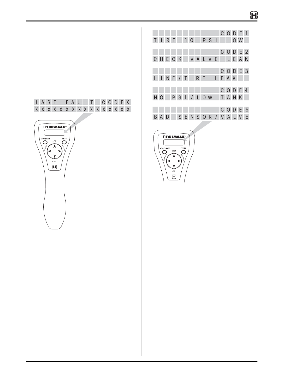
• Display fault code history
NOTE: The hand-held programming device is not
required to identify the fault that caused the
trailer mounted warning lamp to illuminate.
Before power is removed from the trailer, the
LED on the controller assembly will blink a
code associated with the fault that caused the
warning lamp to illuminate (refer to the blink
code descriptions in Hendrickson publication
L818,
TIREMAAX
®
Installation, Service and
Troubleshooting Procedures
for more details).
However if the blink code was not observed
before power was removed from the trailer, the
hand-held programming device will be needed
to reveal the last fault code stored before
power was removed.
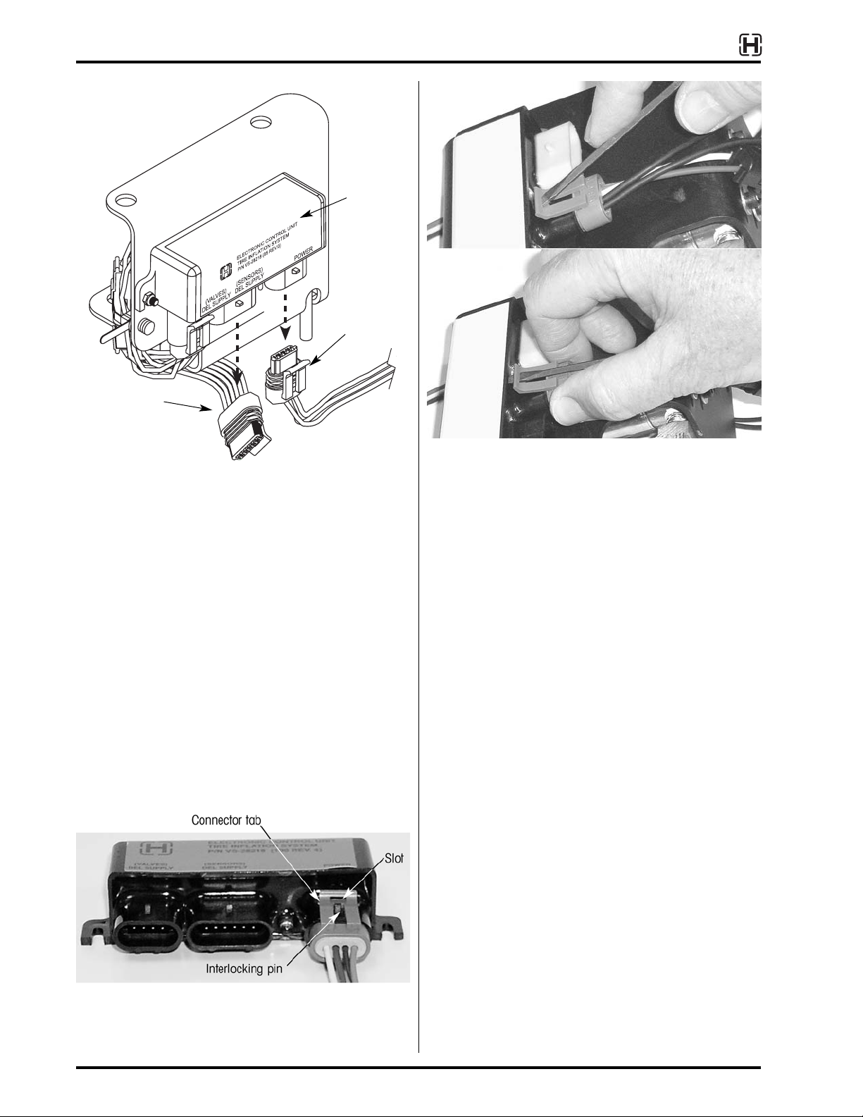
To use the hand-held programming device for any of
these tasks, it must first be connected to the
TIREMAAX®EC controller assembly, between the
pressure sensors and the ECU. When connected, the
hand-held programming device will be powered from
the trailer power circuit and is ready for use. No
additional power supplies or on / off switches are
required to use the hand-held programming device.
Use the following procedure to connect the hand-held
programming device to the controller assembly.
IMPORTANT: Do not vary the connection order from
what is presented in the following steps.
The last connection made must be the
four-pin trailer power cable into the
hand-held programming device.
HAND-HELD PROGRAMMING DEVICE
CONNECT PROCEDURE
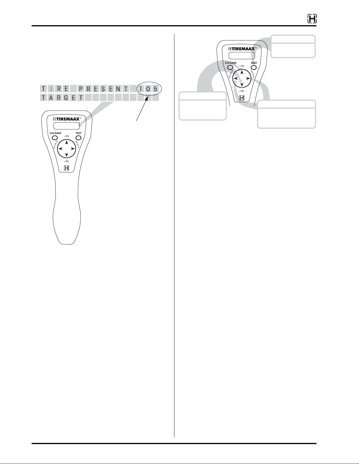
1. Power the trailer.
The hand-held programming device derives
power from the trailer, so the trailer must be
powered for the hand-held programming device
to function.
NOTE: Do not plug the four-pin trailer power cable
into the hand held programming device at this
time. This connection must be the last one
made in order for the hand-held programming
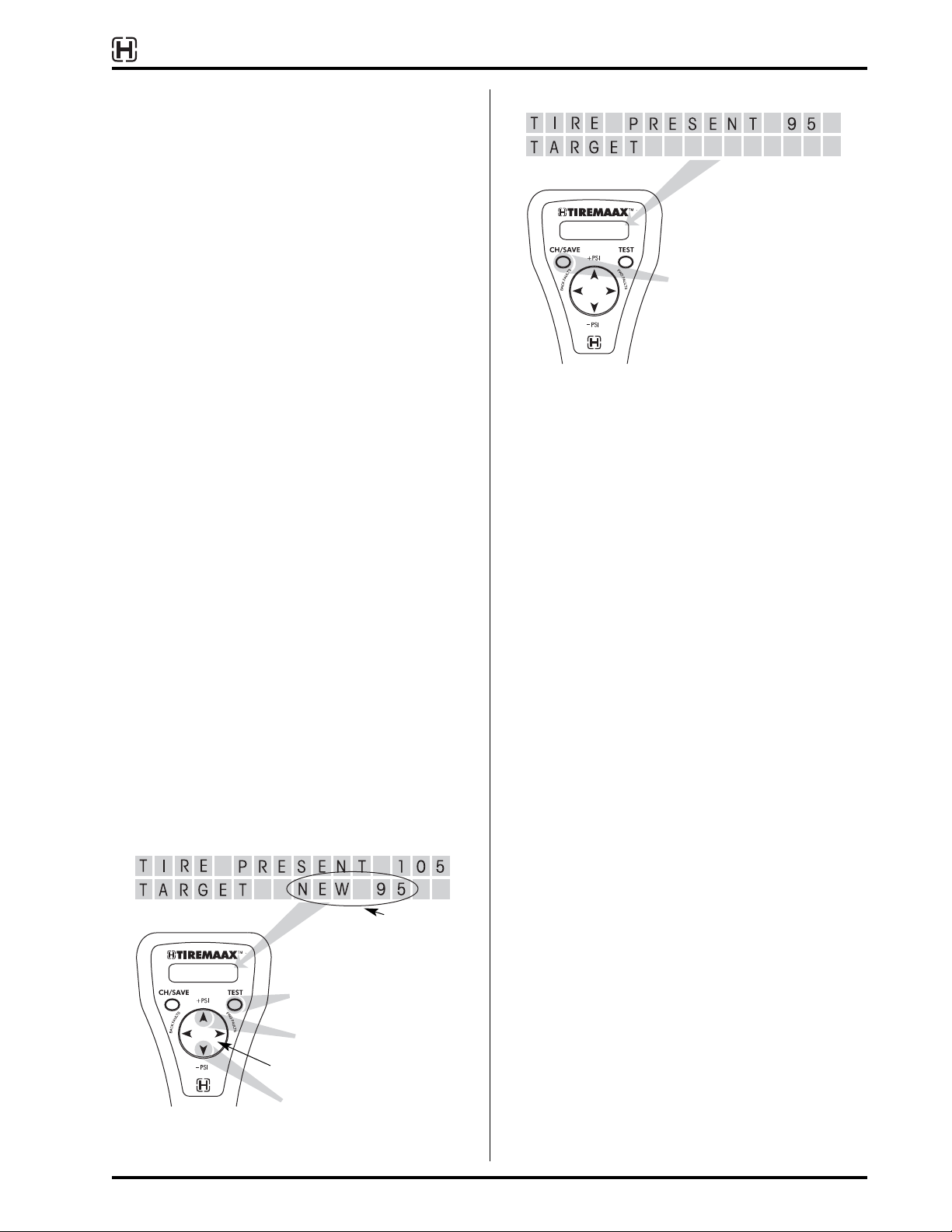
device to properly enter the target pressure
setting mode.
2. Pressurize the trailer air tank (optional).
If you wish to run the diagnostics to functionally
check the solenoid valves and pressure sensors,
the trailer must have enough air pressure (90
psi) to open the pressure protection valve on the
trailer air tank. If you do not wish to run the
diagnostics, this step can be skipped.
CAUTION: Potential overinflation hazard. When
performing diagnostics, the trailer air
tank pressure MUST NOT be higher
than the target pressure setting.
If the trailer air tank pressure is
higher, the tires will overinflate when
both supply and delivery solenoid
valves are opened at the same time.
No method exists to exhaust the
overinflated tires, other than
disconnecting the tire hoses and
manually depressing the valve stem
core at each tire.

TIREMAAX®EC HAND-HELD PROGRAMMING DEVICE OPERATION
4L867A
3. Unplug the four-pin trailer power cable from the
controller assembly ECU (figure 1).
NOTE: To unplug the connectors, insert the tip of a
small flat blade screwdriver into the slot on the
connector tab and GENTLY push down on the
screwdriver to disengage the tab from the
interlocking pin (figures 2 and 3). With the tab
disengaged, gently pull the connector apart
(figure 3). DO NOT overbend the tab. Even
though the connector is made of a resilient
plastic, it is possible to damage the connector
if excessive force is used.
4. Unplug the six-pin sensor cable from the
controller assembly ECU (figure 1).
5. Plug the four-pin connector from the hand-held
programming device into the open four-pin
socket on the controller assembly ECU
(connection A, figure 4, the four-pin socket next
to the LED).
6. Plug the six-pin connector from the hand-held
programming device into the open six-pin socket
on the controller assembly ECU (connection B,
figure 4).
7. Plug the six-pin sensor cable from the controller
assembly into the six-pin socket on the hand-
held programming device (connection C, figure
4).
8. Plug the four-pin trailer power cable into the four-
pin socket on the hand-held programming device
(connection D, figure 4).
Figure 1. Unplugging the power and sensor cables
four-pin
trailer
power cable
Six-pin sensor
cable
ECU
Figure 2. Typical connector items
Figure 3. Connector unplugging technique

TIREMAAX®EC HAND-HELD PROGRAMMING DEVICE OPERATION
5
L867A
POWER
(SENSORS)
DEL SUPPLY
HAND HELD PROGRAMMER
TIREMAAX
P/N VS-28234
A
B
C
D
Figure 4. Connecting the hand-held programming device to the controller assembly ECU
Make this
connection last
four-pin trailer
power cable
Six-pin
sensor cable
Hand-held programming
device
Controller
assembly

TIREMAAX®EC HAND-HELD PROGRAMMING DEVICE OPERATION
6L867A
When connected as described, the hand-held
programming device will automatically enter the tire
pressure setting mode. The tire pressure setting mode
displays the present target pressure setting in the
upper right corner of the display (figure 5).
If you don’t see this screen on the hand-held
programming device, unplug everything and
reconnect the hand-held programming device in the
order previously described. Make sure the last
connection made is the four-pin trailer power cable to
the hand-held programming device.
The hand-held programming device has three
operational modes:
• target pressure setting mode
• diagnostic test mode
• fault code history mode
The target pressure setting mode is always the first
mode entered when the hand-held programming
device is powered. To navigate to the other
operational modes, use the TEST button, BACK
FAULTS or FWD FAULTS arrows, and the +PSI or -PSI
arrows as shown in figure 6.
TARGET PRESSURE SETTING
The target pressure setting mode is used to program
a different tire pressure setting into the TIREMAAX®EC
controller.
NOTE: For TIREMAAX EC to function properly, the
trailer air tank pressure must be higher than
the target tire pressure. TIREMAAX EC is only
capable of allowing available air tank pressure
to reach the tires. It is not capable of supplying
pressure above the available air tank pressure.
When the target pressure setting mode is entered, the
display shows the present target pressure setting
(figure 5). This screen provides a visual indication
that you are in the target pressure setting mode.
1. To select a different pressure setting:
Press the +PSI arrow on the direction pad to
increase the target pressure setting or the -PSI
arrow on the direction pad to decrease the target
pressure setting (figure 7).
Each time the +PSI or -PSI arrow is pressed, the
target pressure setting is raised or lowered by
five psi and the display shows the newly
selected pressure setting (figure 7). Possible
target pressure settings are 70, 75, 80, 85, 90,
95, 100, 105, 110, 115, 120, 125 and 130.
Figure 5. Initial target pressure setting mode display
Present target
pressure setting
Diagnostic
test mode
TEST*
Press: To go to:
Fault code
history
mode
BACK FAULTS*
or
FWD FAULTS*
Press: To go to:
Target
pressure
setting mode
+PSI
or
-PSI
Press: To go to:
*In the target pressure
setting mode, pressing
TEST once reverts to the
present pressure setting.
A second press takes you
to the diagnostic test
mode.
*In the target pressure setting mode,
pressing the BACK FAULTS or FWD
FAULTS arrow once reverts to the
present pressure setting. A second
press takes you to the fault code
history mode.
Figure 6. Navigating through the operational modes

TIREMAAX®EC HAND-HELD PROGRAMMING DEVICE OPERATION
7
L867A
2. Press the TEST button to cancel or reset the new
target pressure setting. The lower right corner of
the display will clear and the upper right corner
of the display will revert to the present (or saved)
target pressure setting (the same pressure setting
that was in effect when the target pressure setting
mode was first entered).
In the target pressure setting mode, before the
CH/SAVE button is pressed, one press of the
TEST button, BACK FAULTS or FWD FAULTS arrow
acts as a “reset” or “do over” function. A second
press of the TEST button changes focus to the
diagnostic mode, and a second press of the
BACK FAULTS or FWD FAULTS arrow changes
focus to the fault code history mode.
3. Press the CH/SAVE (change / save) button to
save the new target pressure setting (figure 8).
The display will show the newly selected
pressure setting in the upper right corner of the
display as the present target pressure setting.
4. Disconnect the hand-held programming device
or go to one of the other operational modes.
If you wish to disconnect the hand-held
programming device, refer to the disconnect
procedure on page 11 (the four-pin trailer power
cable must be the first one disconnected from the
hand-held programming device and the last one
connected to the controller assembly ECU).
If you wish to go to the diagnostic test mode,
press the TEST button.
If you wish to go to the fault code history mode,
press either the BACK FAULTS or FWD FAULTS
arrow on the direction pad.
New target
pressure setting
Increases pressure setting
Decreases pressure setting
Figure 7. Selecting a different target pressure setting
Direction pad
TEST button, BACK FAULTS or
FWD FAULTS arrow can be used
to cancel or reset the new target
pressure setting, (reverts to
present setting)
Figure 8. Saving the new target pressure setting
Saves pressure setting

TIREMAAX®EC HAND-HELD PROGRAMMING DEVICE OPERATION
8L867A
DIAGNOSTIC TEST OPERATION
The diagnostic test mode can be used to toggle the
trailer mounted warning lamp and controller
assembly LED, the delivery solenoid valve and the
supply solenoid valve on and off to see if these
components respond properly. The diagnostic test
mode also displays delivery and supply pressure
sensor outputs in psi.
NOTE: Temporarily disconnect (unscrew) a wheel
hose at the tee fitting on the wheel after
entering the diagnostic test mode. This will
prevent inadvertent tire overinflation during
solenoid valve response testing when both
supply and delivery solenoids are opened at
the same time.
When the diagnostic test mode is entered, the display
shows the supply and delivery pressure sensor
outputs and the current state of the trailer mounted
warning lamp (figure 9). This screen provides a
visual indication that you are in the diagnostic test
mode.
1. To test the trailer mounted warning lamp and
controller assembly LED response:
Press the CH/SAVE (change / save) button to
toggle the trailer mounted warning lamp and LED
from off to on (figure 10). Press the CH/SAVE
button again to toggle from on to off.
The trailer mounted warning lamp and controller
assembly LED will remain in the last state
chosen (either on or off) when the diagnostic
focus is changed in the next step.
Figure 9. Initial diagnostic test mode display
Figure 10. Testing the trailer mounted warning lamp and
controller assembly LED response
Toggles warning lamp
Display toggles with each press of the CH/SAVE button
Figure 11. Testing the supply solenoid valve (SUP) response
2. Toggles supply solenoid
valve (SUP) on or off
Display toggles with each press of the CH/SAVE button
1. Shifts focus to supply
solenoid (SUP)

TIREMAAX®EC HAND-HELD PROGRAMMING DEVICE OPERATION
9
L867A
2. To test the supply solenoid valve response, press
the TEST button (figure 11). The diagnostic focus
shifts from the warning lamp to the supply
solenoid valve.
Press the CH/SAVE (change / save) button to
toggle the supply solenoid valve from off to on.
Press the CH/SAVE button again to toggle the
valve from on to off (figure 11).
CAUTION: Potential overinflation hazard. When
performing diagnostics, the trailer air
tank pressure MUST NOT be higher
than the target pressure setting.
If the trailer air tank pressure is
higher, the tires will overinflate when
both supply and delivery solenoid
valves are opened at the same time.
No method exists to exhaust the
overinflated tires, other than
disconnecting the tire hoses and
manually depressing the valve stem
core at each tire.
The supply solenoid valve will remain in the last
state chosen (either on or off) when the
diagnostic focus is changed in the next step.
3. To test the delivery solenoid valve response,
press the TEST button (figure 12). The diagnostic
focus shifts from the supply solenoid valve to the
delivery solenoid valve.
Press the CH/SAVE button to toggle the delivery
solenoid valve from off to on. Press the CH/SAVE
button again to toggle the valve from on to off
(figure 12).
The delivery solenoid valve will remain in the last
state chosen (either on or off) when shifting to
another mode of operation.
When warning lamp and solenoid valve
response testing is complete, set all responses to
the OFF state and reconnect the wheel hose at
the tee fitting.
4. Disconnect the hand-held programming device
or go to one of the other operational modes.
If you wish to disconnect the hand-held
programming device, refer to the disconnect
procedure on page 11 (the four-pin trailer power
cable must be the first one disconnected from the
hand-held programming device and the last one
connected to the controller assembly ECU).
If you wish to go to the target pressure setting
mode, press the +PSI or -PSI arrow on the
direction pad.
If you wish to go to the fault code history mode,
press the BACK FAULTS or FWD FAULTS arrow on
the direction pad.
Figure 12. Testing the delivery solenoid valve (DEL) response
2. Toggles delivery solenoid valve
(DEL) on or off
Display toggles with each press of the CH/SAVE button
1. Shifts focus to delivery
solenoid (DEL)

TIREMAAX®EC HAND-HELD PROGRAMMING DEVICE OPERATION
10 L867A
FAULT CODE HISTORY OPERATION
The fault code history mode is used to review fault
codes that have been stored in the TIREMAAX®EC
controller.
When the fault code history mode is entered, the
display will show the last recorded fault (figure 13).
This screen provides a visual indication that you are
in the fault code history mode.
There are five possible fault codes that can be
displayed in the fault code history mode (figure 14).
The upper right corner of the fault code display shows
the fault code number. This number will match the
number of times the LED on the controller assembly
blinks when a fault is detected. The bottom line of the
display contains a brief description of the fault. Refer
to the Blink Code Descriptions section in Hendrickson
publication L818,
TIREMAAX
®
Installation, Service
and Troubleshooting Procedures
for additional fault
details.
1. Press the BACK FAULTS arrow on the direction
pad to go back through the six most-recently
recorded faults (figure 15).
2. Press the FWD FAULTS arrow on the direction
pad to go forward through the six most-recently
recorded faults (figure 15).
The upper left corner of the display identifies the
fault by its relationship to the last fault
(figure 15).
After reviewing the fault code history, the nature of the
fault can be identified and the following steps can be
taken to correct the fault:
a. Disconnect the hand-held programming device
and reconnect the proper cables to the ECU on
the controller assembly, but do not apply power
to the trailer.
b. Fix the fault and pressurize the trailer air tank to
at least five psi above the target pressure.
c. After the trailer air tank is adequately pressurized,
apply power to the trailer.
Figure 14. Possible fault codes
Figure 13. Initial fault code history mode display
(The X’s are specific
to each fault code)

TIREMAAX®EC HAND-HELD PROGRAMMING DEVICE OPERATION
11
L867A
When the controller is repowered, it will go into its
normal operating mode. As the controller proceeds
through its system routines, it will assume the fault
has been corrected.
If the fault was not fixed, the controller will detect it
and the LED on the controller assembly will blink the
fault code. This LED blink code will be adequate to
diagnose issues until resolved, without needing to re-
attach the hand-held programming device. Every time
power is removed from the controller and then
reapplied, it will assume the fault has been corrected
and will not repeat a fault code unless it detects the
same one again.
A fault code will not be stored as a repeated code
unless the same fault is the first one recorded after a
power up. If the same fault is displayed in two
consecutive locations in the fault code history, the
fault was redetected after controller power was
reconnected.
It is not possible to clear faults from the register.
When a new fault is detected, it becomes the last
fault and all pre-existing faults shift one location.
The last location, the sixth fault, gets overwritten.
3. Disconnect the hand-held programming device
or go to one of the other operational modes.
If you wish to disconnect the hand-held
programming device, refer to the following
disconnect procedure (the four-pin trailer power
cable must be the first one disconnected from the
hand-held programming device and the last one
connected to the controller assembly ECU).
If you wish to go to the target pressure setting
mode, press the +PSI or -PSI arrow on the
direction pad.
If you wish to go to the diagnostic test mode,
press the TEST button twice. Pressing the TEST
button once takes you to the target pressure
setting mode. The second press will take you to
the diagnostic test mode.
HAND-HELD PROGRAMMING DEVICE
DISCONNECT PROCEDURE
1. Unplug the four-pin trailer power cable from the
hand-held programming device. Do not plug this
connector back into the controller assembly ECU
at this time, it will be reconnected in step six.
2. Unplug the six-pin sensor cable from the hand-
held programming device.
3. Unplug the hand-held programming device six-
pin connector from the controller assembly ECU.
4. Unplug the hand-held programming device four-
pin connector from the controller assembly ECU.
5. Plug the six-pin sensor cable back into the six-
pin connector on the controller assembly ECU.
6. Plug the four-pin trailer power cable back into the
four-pin connector on the controller assembly
ECU.
7. Observe the LED on the controller assembly.
Make sure it does not blink a fault code
associated with loose or leaking tire hoses.
Figure 15. Stepping through the fault code history
Steps forward through fault history
Steps backward through fault history

www.hendrickson-intl.com
Information contained in this literature was accurate at the time of publication. Product changes may have been made after the copyright date that are not reflected.
© 2007 Hendrickson USA, L.L.C. (U.S. Rights) Hendrickson International Corporation (Rights Outside U.S.) All Rights ReservedL867 Rev A 06-07 ECN 15822
Trailer Suspension Systems
250 Chrysler Drive, Unit #3
Brampton, ON Canada L6S 6B6
905.789.1030
Fax 905.789.1033
Trailer Suspension Systems
Av. Industria Automortriz #200
Parque Industrial Stiva Aeropuerto
Apodaca, N.L., México C.P. 66600
(52) 81 8288 1300
Fax (52) 81 8288 1301
Trailer Suspension Systems
2070 Industrial Place SE
Canton, OH 44707-2641 USA
866.RIDEAIR (743.3247)
330.489.0045
Fax 800.696.4416
Printed in United States of America
Table of contents
Other Hendrickson Automobile Accessories manuals