Henkel Loctite EQ PR10.1 DLP User manual

Loctite®EQ PR10.1 DLP 3D Printer
Operating Manual
IDH 2416987

2
Contents
1
Please observe the following ..................................................................................................4
1.1
Emphasised Sections........................................................................................................ 4
1.2
Items Supplied.................................................................................................................. 4
1.3
Field of Application (Intended Usage).............................................................................. 4
1.4
For Your Safety................................................................................................................. 5
2
Technical Data ................................................................................................................. 6
3
Description....................................................................................................................... 6
3.1
Theory of Operation......................................................................................................... 6
3.2
Machine Overview ........................................................................................................... 7
3.3
Machine Connections....................................................................................................... 8
3.4
Touchscreen Menus ......................................................................................................... 9
4
Installation ..................................................................................................................... 12
4.1
Environmental and Operating Conditions ..................................................................... 12
4.2
Levelling the Printer ....................................................................................................... 12
4.3
Connecting the Supplies................................................................................................. 12
4.4
Removing the Projector Cap .......................................................................................... 12
4.5
Asssembling the Build Platform ..................................................................................... 12
4.6
Assembling the Basins.................................................................................................... 13
4.7
Installing the Safety Basin .............................................................................................. 14
4.8
Installing the Resin Basin................................................................................................ 16
4.9
Run the Diagnostics Check ............................................................................................. 17
4.10
Positioning the Build Platform ....................................................................................... 19
4.11
Alligning the Build Platform ........................................................................................... 20
5
Loctite Operator Station PC Software .......................................................................... 23
5.1
Installing the Software ................................................................................................... 23
5.2
Main Screen.................................................................................................................... 24
5.3
Adding a Printer ............................................................................................................. 31
6
Calibration...................................................................................................................... 32
6.1
Create a Calibration Print............................................................................................... 32
6.2
Print a Calibration Print.................................................................................................. 32
6.3
Measure the Calibration Values..................................................................................... 33
7
Operation....................................................................................................................... 34
7.1
Create a Print Job ........................................................................................................... 34
7.2
Preperations Before Printing.......................................................................................... 34
7.3
Printing ........................................................................................................................... 34
7.4
Remoiving the Build Platform ........................................................................................ 35
7.5
Cleaning the Build Platform ........................................................................................... 36

3
7.6
Cleaning the Basin ..........................................................................................................36
7.7
Removing a Failed Print..................................................................................................37
8
Troubleshooting.............................................................................................................38
9
Care and Maintenance ..................................................................................................39
10
Spare Parts and Accessories ..........................................................................................39
11
Warranty ........................................................................................................................40
4
1
Please observe the following
For safe and successful operation of the unit, read these instructions completely. The
manufacturer cannot be held responsible for damage or injury of any kind because of misuse or
improper application or because of failure to observe safety instructions or warnings.
Be sure to retain this manual for future reference.
1.1
Emphasized Sections
Warning!
Refers to safety regulations and requires safety measures that protect the operator or other
persons from injury or danger to life.
Caution!
Emphasizes what must be done or avoided so that the unit or other property
is not damaged.
Notice
Gives recommendations for better handling or adjustment of the unit during operation as well as
for service activities.
1.2
Items Supplied
1 EQ PR10.1 DLP 3D Printer
1 Base Frame or Cabinet
1 Safety Basin
1 Starter kit –Including:
•1 Spatula
•1 Resin Puller
•1 Resin Curing Flash Light
•1 Resin Basin
•1 Build Platform
•1 Nitrile Gloves
•1 Spray bottle
•1 Funnel with filter
1 Operating Manual
1 PC Software on USB flash drive.
1 Power cord
1 Lens Cap
Notice
Illustrations and descriptions in this instruction manual can deviate in detail from the actual unit
delivered, due to ongoing upgrades.
1.3
Field of Application (Intended Usage)
The Loctite PR10.1 DLP 3D Printer is designed for use with Loctite 3DP resins.
The Loctite PR10.1 can print parts with complex geometries which would be impossible using
traditional manufacturing techniques.

5
1
Please observe the following
1.4
For Your Safety
Request the technical data sheet and the safety data sheet for the LOCTITE®product used at
www.loctite.com.
FOLLOW UNCONDITIONALLY THE INSTRUCTIONS OF THESE DATA SHEETS!
WARNING!
For safe and successful operation of the unit, read these instructions completely.
If the instructions are not observed, the manufacturer can assume no responsibility.
Removing, bypassing or putting out of operation safety devices can result in damage to persons
and damage to the unit and is therefore prohibited!
Damage to the power cord or the housing can result in contact with live electrical parts. Check
the power cord and the unit before each use. If the power cord or the unit is damaged, do not
operate! Replace a damaged power cord with a new one.
The unit may be opened and repaired only by authorized service personal.
Avoid contact with chemicals and wear protective clothing, gloves and goggles.
Do not look directly at Projector-UV light, or at projector-UV light reflected by a reflective
surface. Doing so could cause eye damage.
Always wear UV blocking eye protection when operating this machine.
Never operate this product any way other than described in this manual. Doing so risks exposure
to LED-UV light.
Any defects found must be reported immediately! Remedy any defects immediately!
Use only original replacement and spare parts. Henkel cannot be held responsible for damage or
injury of any kind because of failure to observe the instructions in this Operating Manual.
Mechanical parts are moving slowly but with high forces and rigidity. Keep hands out of the
printer when the axis in moving.
The printer is a tall and heavy part. Make sure it stands well and cannot fall over. Take care when
installing or transporting it. Make sure it is well fixated on the base cabinet with the included
screws.

6
2
Technical Data
Power supply
110 V AC 60 Hz - 240 V AC 50 Hz
Projector
Full HD 1920 x 1080 pixels
Build Volume W x D x H
192mm x 108mm x 250 mm
Print Resolution X and Y Axis
100µm
Print Resolution Z axis
(Layer Thickness)
12 µm - 100 µm
Resin dependent
Overall Dimensions W x D x H (mm)
490 x 420 x 1700
Weight
Approx. 56 kg
Optimal Operating Temperature
22° C (71°F)
Build Platform
Anodized aluminum
Resin Basin
Exchangeable basin glass bottom coated with ultra-high
chemical resistance PTFE.
3
Description
3.1
Theory of Operation
The operator loads resin into the resin basin and selects a print job which has been prepared on
the supplied printer PC software. The software requires a Windows 10 operating system.
The build platform then lowers into the resin and the projector projects an image of the part
layer by layer as the build platform is raised to create a complete part.
Once the print is completed the operator removes the build platform from the printer and the
printed part is detached from the build platform.
7
3
Description
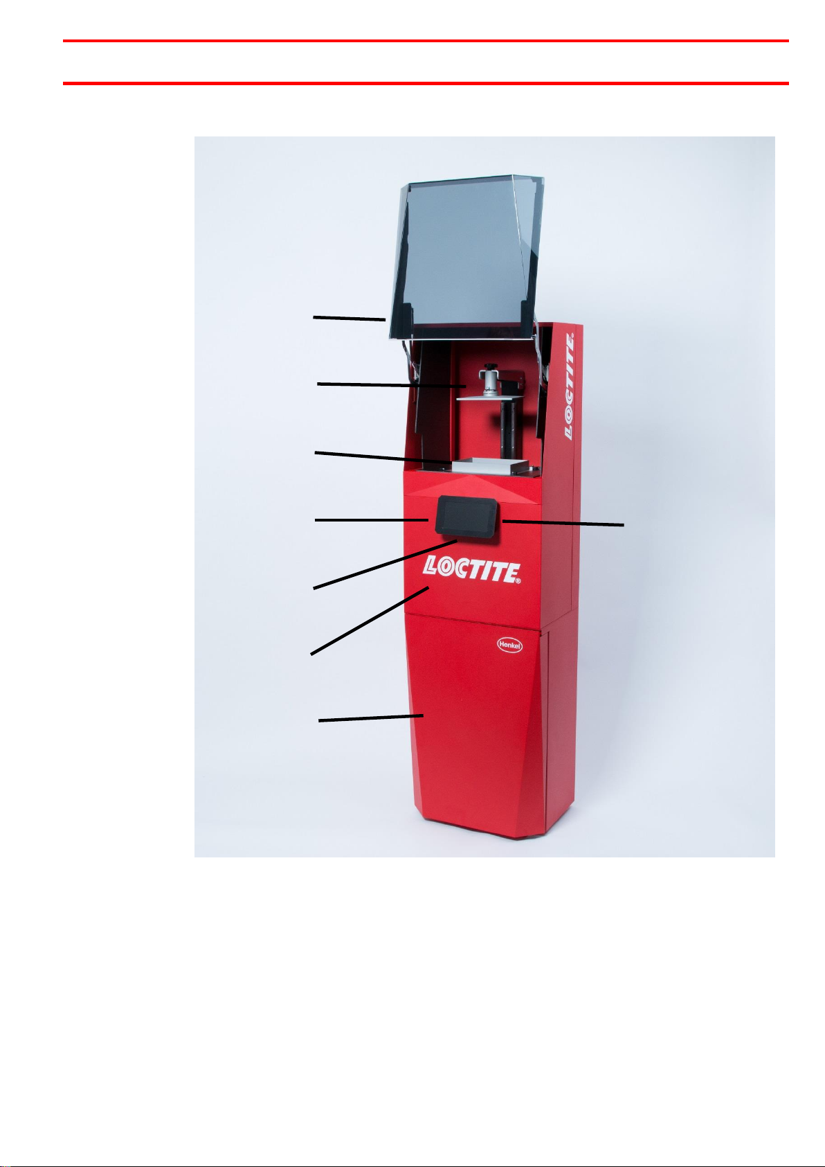
3.2
Machine Overview
1
Protective Cover (UV blocking)
2
Build Platform
3
Resin Basin
4
Touch Screen
5
On/Off Switch –located on the underside of the touch screen.
6
DLP Projector Housing
7
Storage Cabinet
8
USB Connection –located on the right-hand side of the touch screen.
1
2
3
4
5
6
7
8
8
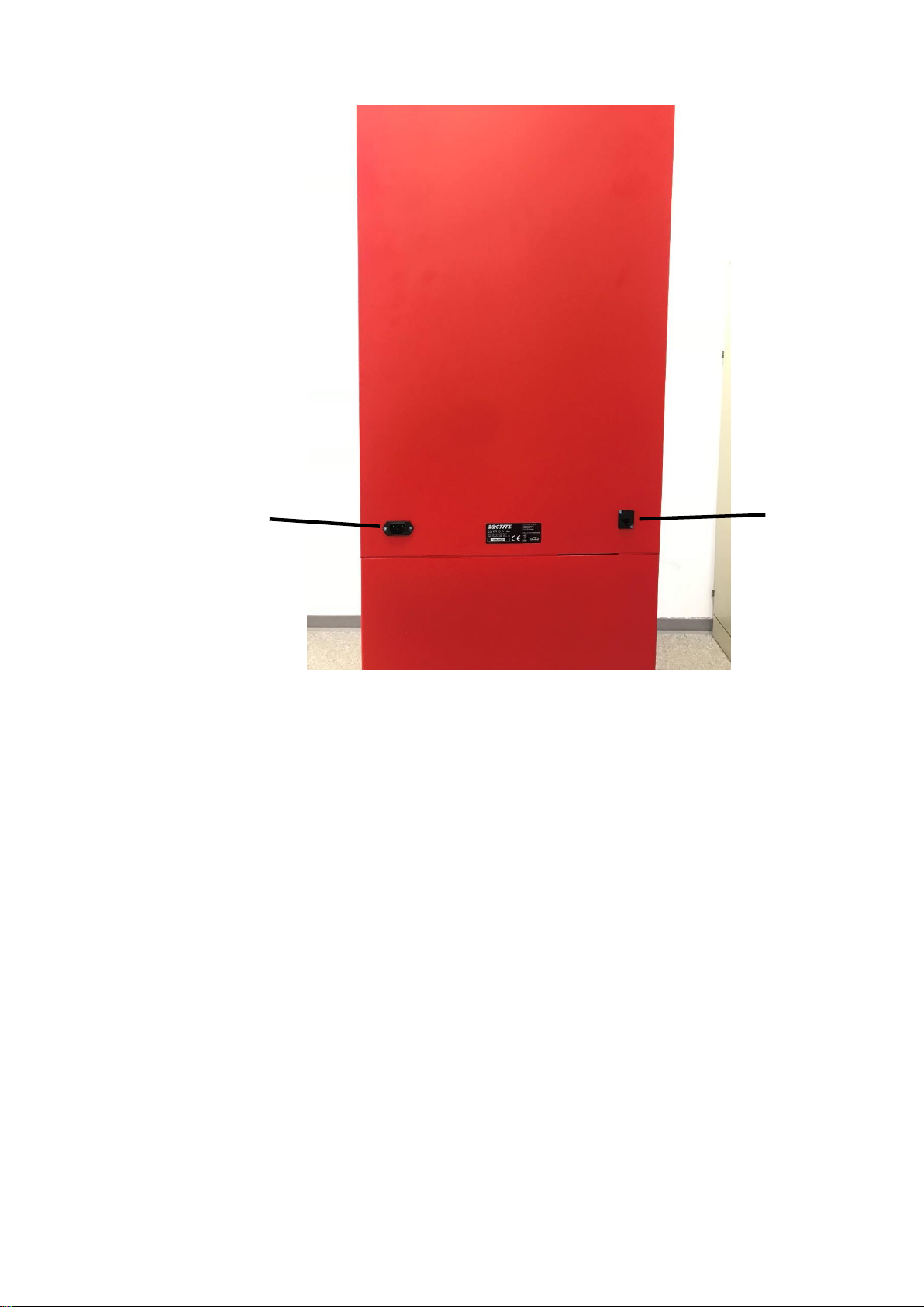
3.3
Machine Connections
21
Power Connector
22
Ethernet Connector
21
22
9
3
Description
3.4
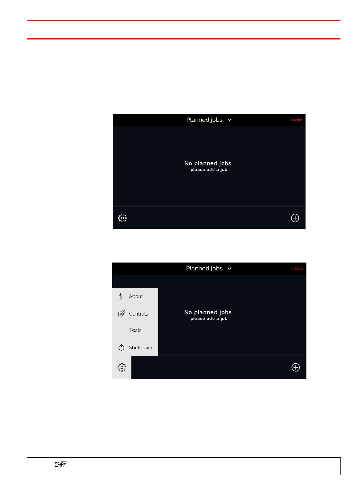
Touchscreen Menus
3.4.1
Menu Overview
Menus include text, making them largely self-explanatory. The most important points are
described in the following.
Menu Group: Home Screen –No Planned Jobs
From this screen you can add print jobs, by pressing the ‘plus’ icon. You can also open the
settings menu by pressing the ‘gear’ icon.
Menu Group: Settings Menu
The settings menu is accessed by pressing the ‘gear’ icon on the home screen. This menu allows
you to access other screens which contain the following information:
ABOUT: Firmware for both the printer and the touchscreen. Print Information including number
of items printed and total number of layers. Network information including Hostname and LAN
information.
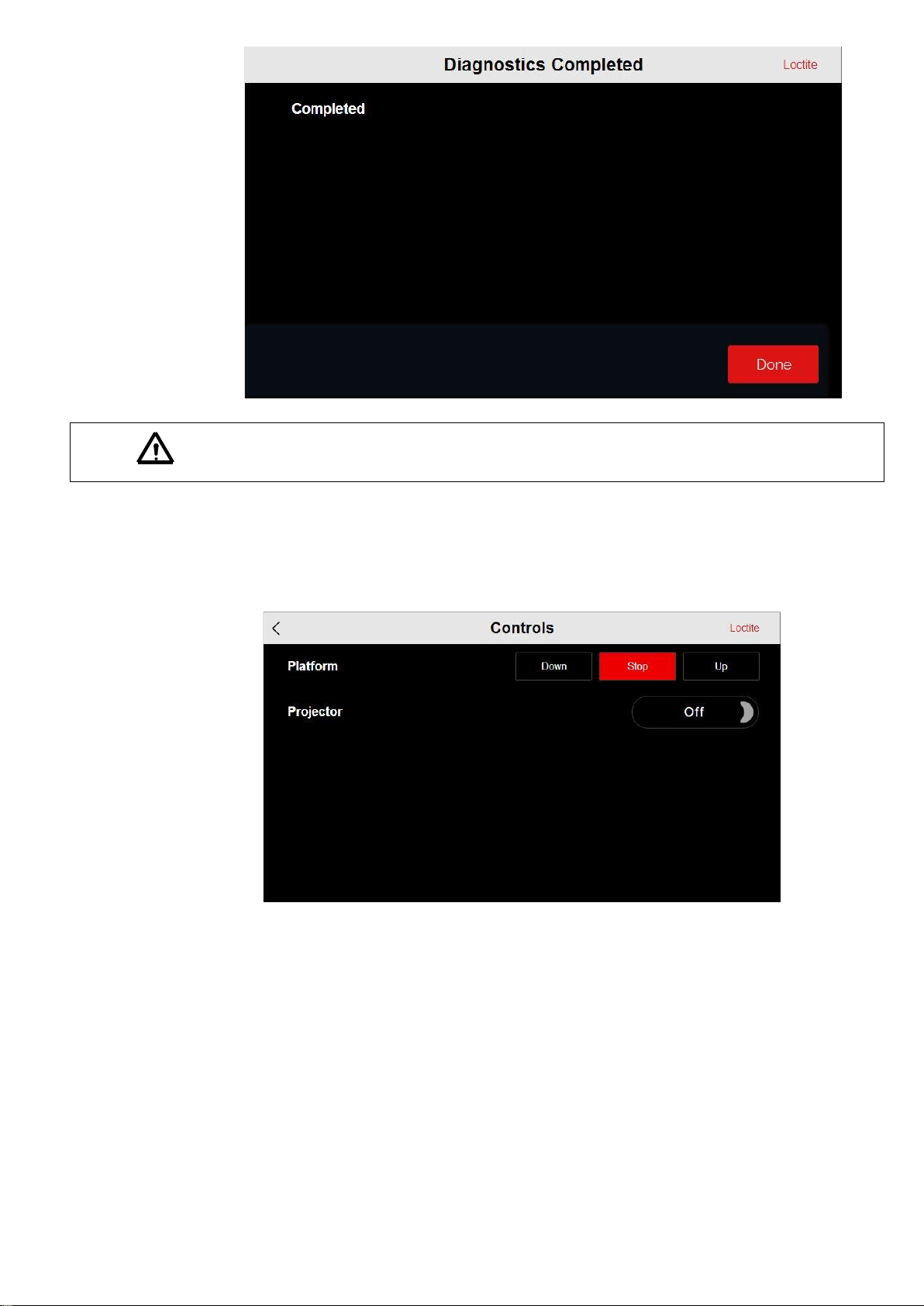
CONTROLS: Manually move the build platform up and down. Manually turn the projector on and
off.
TESTS: Run a diagnostics test, or run a resin test
SHUTDOWN: Shuts down the system.
Always shutdown the system using the ‘Shutdown’ button. Do not just switch off using the
On/Off switch as the integrated file systems could get damaged.

10
Menu Group: Add a Print
This menu is accessed by pressing the ‘plus’ icon on the home screen. From this menu you can
select a print job for printing from a USB flash drive.
This displays each available print job on the USB flash drive and the corresponding approximate
print times and the volume of resin required to print.
Print jobs are selected by pressing the ‘tick’ on the right-hand side, and then pressing the ‘Add’
button. Several print jobs can be copied at once on the printer.
Menu Group: Home Screen –Print Job Selected
Once a print job has been added it will display on the home screen. You can preview a 3D model
of the print by pressing the ‘Preview’ button.

11
The job can be deleted by swiping left on the ‘Planned Jobs’ screen.
To begin printing press the ‘Start’ button.

12
4
Installation
4.1
Environmental and Operating Conditions
–Do not place in direct sunlight
–Do not place close to a heat source
–Recommended operating temperature range: 17° C to 27°C (63°F to 61°F)
–Ensure the printer is on stable, level ground.
The optimal operating temperature is 22° C (71°F)
4.2
Levelling the Printer
Before use it is required to ensure the printer is level in order to get accurate print results.
Use a spirit level as an aid to level the printer by adjusting the feet on the printer.
Ensure the base is bolted to the ground that the printer is bolted to the base.
4.3
Connecting the Power Cord
Connect one of the supplied power cords to the appropriate supply and connector (21). .
4.4
Remove the Projector Protective Cap
The projector is shipped with the projector cap in place. This must be removed before use.
It is possible to remove the cap by reaching inside the print station from above. If a safety basin
should be preinstalled this has to be removed temporarily to access the cap. See 4.7
4.5
Assembling the Build Platform
The build platform comes pre-assembled but must be aligned to the resin tray, see section 4.10
13
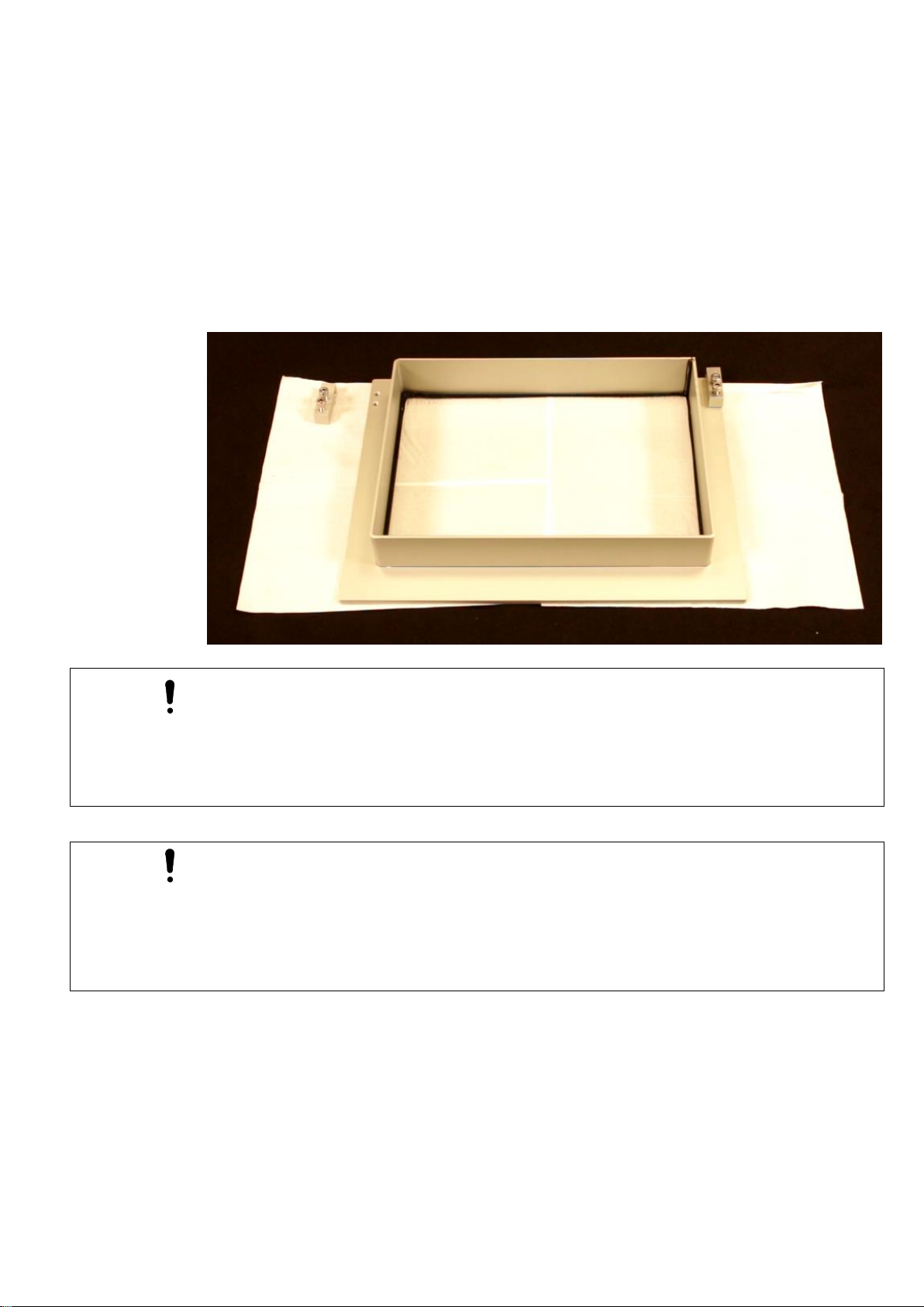
4.6
Assembling the Basins
If the tilt blocks are not yet preassembled on the basins, the safety basin (white silicone used to
bond the glass to frame) and the resin basins (black silicone used to bond glass to frame) must
be assembled prior to use.
To assemble the basin:
1. Unpack the box containing the basin, tilt blocks, screws and pins.
2. Lift the basin from the box by holding the aluminum rim and place it down on a clean
paper towel.
3. Screw the tilt blocks into the frame of the basin. Position the holes in the tilt blocks
towards the back of the basin.
The basins are identifiable by the color of the anodization.
The clear anodization indicates it is a resin basin and has a PTFE coating.
The black anodization indicates it is a safety basin, with no PTFE Coating.
DO NOT INTERCHANGE THE BASINS.
•Do not drop the box containing the basin.
•Do not drop the basin.
•Never touch the inside of the basin with your bare hands.
•Never touch the bottom of the basin with sharp or pointed objects.
•Do not place the basin with the glass flat on a surface. Always place it upside down or
on a clean paper towel.
•Do not rub the bottom of the resin basin to clean it.
14
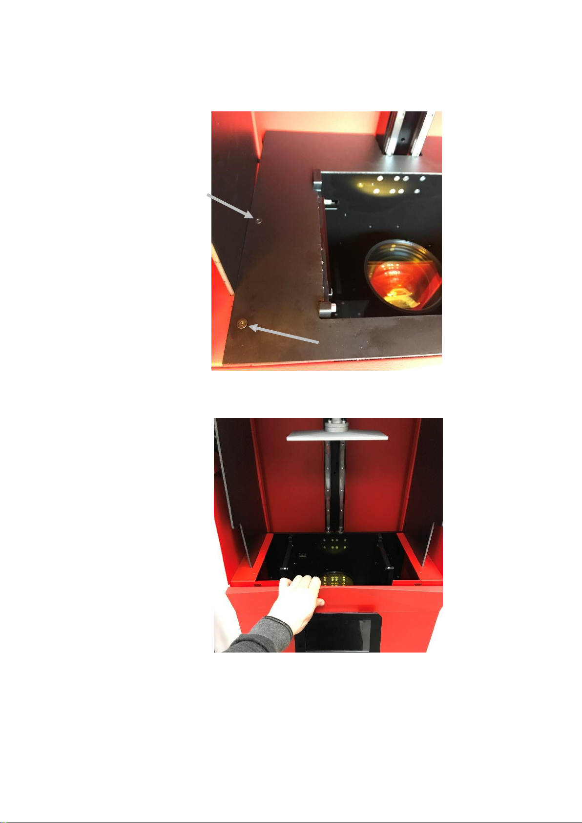
4.7
Installing the Safety Basin
1. Remove the base plate of the printer by removing the four screws holding it in place.
2. Remove the front panel of the printer housing. This is magnetically held in place.
3. Carefully pick up the safety basin (white silicone), holding it gently by the frame.
4. Slide the safety basin into position above the projector, with the tilt blocks facing the
rear of the printer.

15
5. Insert the pins through the tilt block to hold the safety basin in position. Ensure the rings
are on the outside.
It is important the pins are inserted with the rings on the outside as shown below. Failure to
do so could result in the inability to remove the pins.
6. Replace the front panel.
7. Re-attach the base plate and secure into position with screws.

16
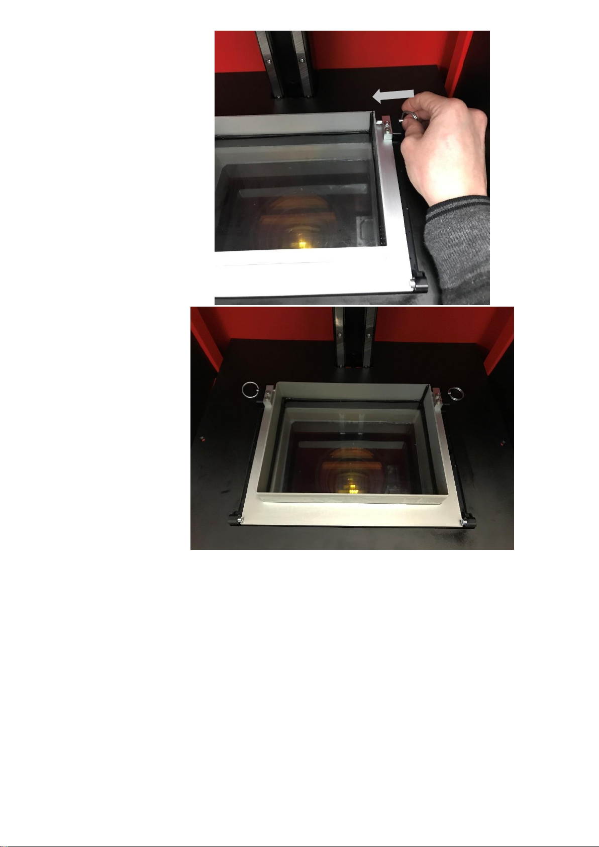
4.8
Installing the Resin Basin
1. Ensure the build platform carriage (Z-axis) is in the top position. - this can be done by
entering the ‘Controls’ screen from the settings menu and pressing the platform ‘Up’
button.”
2. Check the correct basin is being installed –black silicone to indicate PTFE coating.
3. Pick up the basin, holding it by the aluminum frame
4. Move the basin into position above the projection hole, with the tilt blocks positioned
towards the rear of the printer.
5. Tilt the basin downwards at the front and move into position under the stopping blocks.
6. Lower the basin so it is horizontal and resting in position.
7. Align the holes on the tilt blocks with the holes in the frame.
8. Insert the pins to hold the basin in place. Ensure the rings on the pins are on the outside.
It is important the pins are inserted with the rings on the outside, as shown below. Failure to
do so could result in the inability to remove the pins.
Stopping blocks
Tilt blocks
17
4.9
Run Diagnostics Check
The diagnostics check is a built-in function which tests the different functionalities of the printer,
including the projector and z-axis motor. Ensure a USB flash drive is connected prior to running
the diagnostic checks.
To carry out the diagnostics check:
1. Power on the printer using the on/off switch located on the underside of the
touchscreen.
2. Wait for the printer to boot up.
3. Open the settings menu from the home screen by pressing the ‘gear’ button.
4. Select ‘Tests’
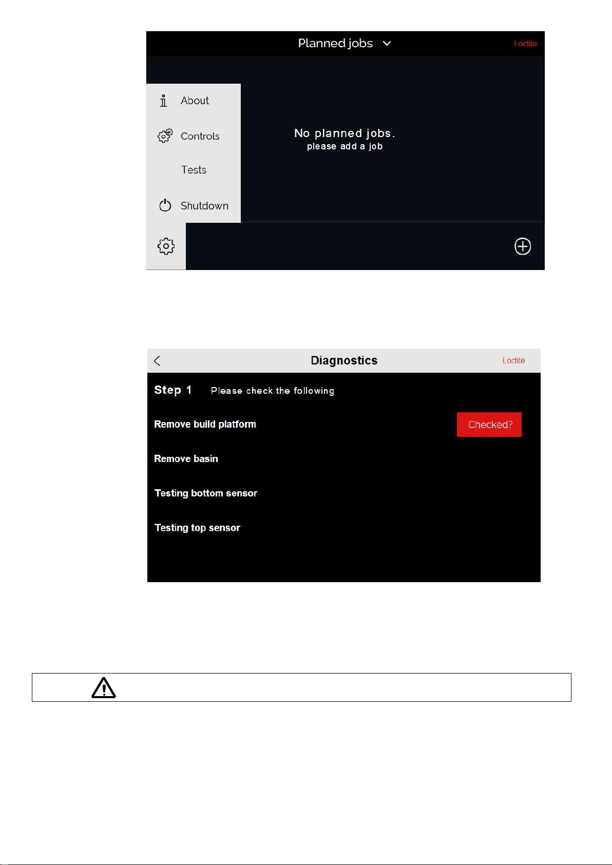
18
5. Select ‘Diagnostics’
6. Complete the checklist as directed on the touchscreen. Press the ‘Checked?’ button to
confirm each action.
7. The diagnostic checks finish with a test print. During the test print the Z axis carriage
lowers to the basin and gradually travels upwards, while the projector flashes the Loctite
logo
8. Once this has completed press ‘Done’ to finish.
Always wear UV blocking safety glasses when the projector is on
19
Please note the z axis carriage will move up and down and the projector will turn on during the
diagnostics checks.
4.10
Positioning the Build Platform
1. Move the z axis carriage to the top position - this is done by entering the ‘Controls’
screen from the settings menu and pressing the platform ‘Up’ button.
2. Set the build platform so that the groove is matching the receiving slot.
3. Ensure it is facing the correct direction and push into position.
4. Screw the manual top screw down and tighten into position.

20
5. The assembly is now in position. With one hand, raise the build platform up to the top
position and tighten the front facing allen key screw. Do not tighten the build platform in
the extended position, it must be at minimum extension for the calibration of the print
tray that follows.
4.11
Aligning the Build Platform
To produce accurate prints, the build platform needs to be aligned with the basin.
To align the build platform:
1. Ensure that the build platform and basin are clean.
2. Move the build platform the top position –this is done by entering the ‘Controls’ screen
from the settings menu.
3. Loosen the 4 screws holding the ball joint so the build platform can freely move in an
angular direction.
Receiving Slot
Table of contents


