Xycom XVME-212 User manual

-~
ARTISAN
®
~I
TECHNOLOGY
GROUP
Your definitive source
for
quality
pre-owned
equipment.
Artisan Technology
Group
Full-service,
independent
repair
center
with
experienced
engineers
and
technicians
on staff.
We
buy
your
excess,
underutilized,
and
idle
equipment
along
with
credit
for
buybacks
and
trade-ins
.
Custom
engineering
so
your
equipment
works
exactly as
you
specify.
•
Critical
and
expedited
services
•
Leasing
/
Rentals/
Demos
• In
stock/
Ready-to-ship
•
!TAR-certified
secure
asset
solutions
Expert
team
ITrust
guarantee
I
100%
satisfaction
All
tr
ademarks,
br
a
nd
names, a
nd
br
a
nd
s a
pp
earing here
in
are
th
e property of
th
e
ir
r
es
pecti
ve
ow
ner
s.
Find the Acromag / Xembedded / Xycom XVME-212/1 at our website: Click HERE

O
1997
XYCOM, INC.
Digital Input
Module
PIN
7421
2-001
B
Printed
in
the United States
of
America
Artisan Technology Group - Quality Instrumentation ... Guaranteed | (888) 88-SOURCE | www.artisantg.com

Xycom Revision Record
I
Revision Description
ManualReleased
ManualUpdated
Date
TrademarkInformation
Brandor product names are registeredtrademarks of their respectiveowners.
CopyrightInformation
This document is copyrighted by Xycom Incorporated(Xycom) and shall not be reproduced or copied
without expressed written authorization from Xycom.
The informationcontainedwithin this document is subject to change without notice.
xycom
Technical Publications Department
750 North MapleRoad
Saline, MI48176-1292
313-429-4971 (phone)
313-429-1010 (fax)
Artisan Technology Group - Quality Instrumentation ... Guaranteed | (888) 88-SOURCE | www.artisantg.com

XVME-212 Manual
August, 1989
TABLE OF CONTENTS
CHAPTER TITLE PAGE
INTRODUCTION
Introduction 1
-
1
Manual Structure 1
-
1
Operational Block Diagram 1-2
Features of Xycom's Standard 1/0 Architecture 1-2
XVME-212 Module Specifications 1-3
INSTALLATION
Introduction 2-1
System Requirements 2-1
Location of Components Relevant to Installation 2-1
Jumpers/Switches 2-3
Base Address Selection Switches (Sl-1 to S1-6) 2-4
Address Space Selection (53) 2-7
Supervisory/Non-privileged
Mode Selection 2-7
Address Modifier Reference 2-7
Interrupt Level Switches (S2) 2-8
IACK Enable Jumpers (Jl, J2) 2-8
Debounce Period Jumpers (54-511) 2-9
Installation 2-9
Installation Procedure 2-11
Digital Input Connections 2-11
Mechanical Switch/Relay Operation 2-13
XVME-21211 2-13
XVME-212/2 2-13
PROGRAMMING
Introduction 3-1
Base Addressing 3-1
1/0 Interface Block
3-3
Module Identification (Base+OlH to 3FH) 3-3
Extended Status and Status/Control Registers 3-5
Extended Status and Status/Control Register
3-6
Bit Definitions
Interrupt Acknowledge (IACK) Vector Register 3-8
Change Registers 3-9
Scanner 3-10
Scanner Operation 3-10
Stopping the Scanner 3-10
Restarting the Scanner 3-11
VMEbus Interrupts 3-11
Artisan Technology Group - Quality Instrumentation ... Guaranteed | (888) 88-SOURCE | www.artisantg.com
XVME-212 Manual
August,
1989
TABLE OF CONTENTS (cont'd)
CHAPTER TITLE
3.1 1 Programming Considerations
3.12 Resetting the Module
FIGURE
TABLE
APPENDICES
XYCOM STANDARD 1/0 ARCHITECTURE
VMEbus
CONNECTOR/PIN DESCRIPTION
SCHEMATICS AND DIAGRAMS
QUICK REFERENCE GUIDE
LIST OF FIGURES
TITLE
PAGE
PAGE
Operational Block Diagram of the XVME-212 1-2
XVME-212 Jumpers, Switches, and Connectors 2-2
Switch Bank S1
-
Base Address Switches 2-5
VMEbus Chassis 2-10
XVME-212 1/0 Interface Block and its Possible 3-2
Locations in Short
1/0
Address Space
Extended Status and Status/Control Registers 3-5
Data Registers (read-only) 3-9
Change Registers (read-only) 3-10
Generating a VMEbus Interrupt 3-12
Relationship of Input Channel Signals with 3-14
Respect to Stopping the Scanner
LIST OFTABLES
TITLE PAGE
XVME-212 Module Specifications 1-3
XVME-212 Jumper/Switch List
Module Base Addresses
Addressing Options (53)
Artisan Technology Group - Quality Instrumentation ... Guaranteed | (888) 88-SOURCE | www.artisantg.com
XVME-212 Manual
August, 1989
LIST OF TABLES (cont'd)
TABLE
2-4
2-5
2-6
2-7
2-8
2-9
3-
1
3-2
TITLE
Privilege Options
Address Modifier Code Options
Interrupt Level Switches (S2)
IACK Enable Jumpers
Debounce Period Jumpers
Input Connector Signal Definitions
Identification Data
LED Status
PAGE
Artisan Technology Group - Quality Instrumentation ... Guaranteed | (888) 88-SOURCE | www.artisantg.com

XVME-212 Manual
August, 1989
Chapter 1
INTRODUCTION
1.1 INTRODUCTION
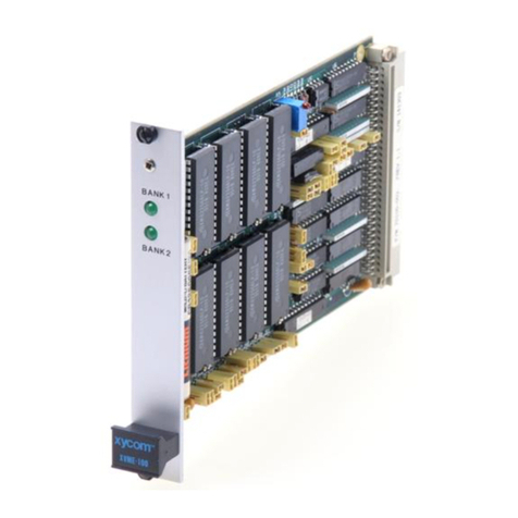
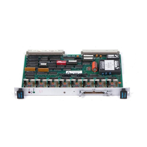
The XVME-212 is a 32 channel, opto-isolated, digital input interface, designed to be
compatible with the VMEbus structure. The XVME-212 is capable of receiving 32 digital
inputs at frequencies up to 3.4 KHz. To ensure signal integrity, the design incorporates
integrated “switch” debouncing, as well as the protection provided by the optical isolation
of the channel inputs from the system bus structure. In addition, an on-board scanner can
be programmed to generate a VMEbus interrupt when any input changes state, thus
eliminating the need to poll the input module.
Each digital input is reverse voltage protected and is capable of handling a maximum
reverse bias of 50V DC (XVME-212/l) or
6.5V
DC (XVME-212/2). Also, the board can be
jumpered to occupy any
1K
block within the short I/O address space.
The following two versions of the XVME-212 are available:
XVME-212/l -- The
/l
version of the XVME-212 comes with an on-board, 12V DC,
isolated power supply. The 12V supply is factory-connected to the input of each channel,
thus permitting the system to monitor 12V relay contacts and switches without an external
power supply. Voltages other than the 12V may be applied to the inputs (within the
l0V-
50V input range); however, some board modification will be necessary (i.e., cutting the
well identified and easily accessible PC traces to the 12V on-board supply).
XVME-212/2 -- The /2 version of the XVME-212 is very similar to the
/I
version except
for the range of allowable input voltage and the absence of an on-board
+12V
DC power
supply. The XVME-212/2 has TTL level inputs with a
6.5V
maximum input. In addition,
the
+12V
isolated, on-board power supply is not available, replaced by wire jumpers to
the existing
+5V
supply of the VME backplane.
1.2 MANUAL STRUCTURE
This first chapter provides a functional overview of the XVME-212 and presents the
features of Xycom’s Standard I/O architecture. Operational aspects of the XVME-212 are
then explained in the following fashion:
Chapter 2
-
Installation: Information required to position the jumpers and switches
on the XVME-212, and install the module in a VMEbus chassis.
Chapter 3
-
Programming: Information required to program the XVME-212 and
read digital input signals.
The appendices at the end of this manual provide information on Xycom’s Standard I/O
Architecture, VMEbus connector/pin descriptions, module schematics, as well as a quick
reference guide to the module’s jumpers and registers.
1-l
Artisan Technology Group - Quality Instrumentation ... Guaranteed | (888) 88-SOURCE | www.artisantg.com
XVME-212 Manual
August, 1989
1.3
OPERATIONAL BLOCK DIAGRAM
Figure 1-1 shows an operational block diagram of the XVME-212.
CHANNELS CHANNELS
16-31
OPTICAL ISOLATOR
L
SCANNER
1
I
CHANGE REGISTERS
1
I
DATA REGISTERS
I
[
VMEbus INTERFACE
I
-
STANDARD
1
110 INTERFACE
T
Figure 1-1. Operational Block Diagram of the XVME-212
1.4
FEATURES OF XYCOM'S STANDARD 1/0 ARCHITECTURE
The XVME-212 and all Xycom 1/0 modules conform to the unique Xycom VMEbus
Standard 1/0 Architecture. This architecture is intended to make the programming of
Xycom VMEbus 1/0 modules simple and consistent. The following features apply to the
operation of the XVME-212:
Module address space
-
The XVME-212 and all VMEbus modules are controlled by
writing to addresses within the
64K
Short 1/0Address space. A VMEbus module can
be switched to occupy any of the
64
available
1K
blocks. This block, known as the
1/0Interface Block, contains all of the module's programming registers and ID data.
Within the 1/0 Interface Block, the offsets are standardized so that the user may
expect to find the sameregisters and data at the same offsets across the entire xycom
VMEbus line.
Artisan Technology Group - Quality Instrumentation ... Guaranteed | (888) 88-SOURCE | www.artisantg.com
XVME-2 12 Manual
August, 1989
- Module identification
-
The XVME-212 has ID information which provides its name,
model number, manufacturer, and revision level at a location that is consistent with
other Xycom I/O modules.
- Status/Control Register
-
This register is always located at address base + 8
lH,
and
the lower four bits (two Test Status bits, and a red and green LED bit) are standard
from module to module.
A detailed description of Xycom I/O Architecture is presented in Appendix A at the rear
of this manual.
1.5 XVME-212 MODULE SPECIFICATIONS
Table l-l. XVME-2 12 Module Specifications
/Characteristic
/
’Number of Channels
Specification
32
~Input Voltage Range (XVME-212/l)
I
I
+5OV
DC max.
Logic 1 -- 10 to
5OV
DC
Logic 0
--
0 to lV DC
Typical threshold 3V
--
DC
:Input Voltage Range (XVME-212/2)
+65V
DC max.
Logic 1 -- 2 to
6.5V
DC
Logic 0 -- 0 to
0.8V
DC
Typical threshold --
1.2V
DC
1Input Impedance
(XVME-2
12/ 1)
3.9K
+5%
:Input Impedance (XVME-2 12/2)
330 +5%
~Propagation Delay
~(with fastest debounce selected)
Of f-to-on 100 usec max. (l0-25 usec typ.)
On-to-off 600 usec max. (150 usec typ.)
~Minimum Detectable Pulse Width
IPositive pulse
I
INegative pulse 100 usec max. (l0-25 usec typ.)
600 usec max. (150 usec typ.)
~Maximum Input Frequency 3.4 KHz typical
Debounce Time Jumper-selectable from 4.5 usec to 18
msec
(8 possible settings)
Reverse Bias Protection (XVME-212/l)
-
50 V max.
Reverse Bias Protection (XVME-2
12/2)
-
6.5V
max.
Power Requirements
+5V,
25%
1.7 Amp typ., 2.0 Amp max.
1-3
Artisan Technology Group - Quality Instrumentation ... Guaranteed | (888) 88-SOURCE | www.artisantg.com
XVME-2 12 Manual
August, 1989
Table l-l. XVME-2 12 Module Specifications (cont’d)
Characteristic Specification
Isolation 300 VDC channel-to-channel
300 VDC channel to VMEbus ground
Board Dimensions NEXP board size
(160mm x 233.4mm)
Environmental Specifications
Temperature
Operating 0’ to 65’C
(32’ to 149’F)
Non-operating -40’ to 85’C
(-40’ to 158’F)
Humidity 5 to 95% RH, non-condensing
(Extremely low humidity conditions may
require special protection against static
discharge.)
Altitude
Operating
Non-operating
Vibration
Operating
Sea level to 20,000 ft.
(6096m)
Sea level to 50,000 ft.
(15240m)
5 to 2000 Hz
.O
15”
peak-to-peak displacement
2.5g
peak acceleration
Non-operating 5 to 2000 Hz
.030”
peak-to peak displacement
5.0 g peak (maximum) acceleration
Shock Operating 30 g peak acceleration,
11 msec duration
I
Non-operating
50 g peak acceleration,
11 msec duration
1-4
Artisan Technology Group - Quality Instrumentation ... Guaranteed | (888) 88-SOURCE | www.artisantg.com

XVME-2 12 Manual
August, 1989
Table
l-
1. XVME-2 12 Module Specifications (cont’d)
Characteristic
-~~
~~~-~
Specification
VMEbus Compliance l Fully compatible with VMEbus standard
l Al
6:D16
Data transfer bus slave
l Base address jumper-selectable within
64K short I/O address space
l Occupies
1K
consecutive byte locations
l I(1) to I(7) Interrupter (STAT) with
programmable vector
l Includes Xycom’s standard I/O module
interface
l NEXP
1-5
Artisan Technology Group - Quality Instrumentation ... Guaranteed | (888) 88-SOURCE | www.artisantg.com
XVME-212 Manual
August, 1989
Chapter 2
INSTALLATION
2.1 INTRODUCTION
This chapter provides the information needed to configure the XVME-212 and to install
it in a VMEbus backplane card cage.
2.2 SYSTEM REQUIREMENTS
The XVME-212 is a double-high VMEbus compatible module. To operate, it must be
properly installed in a VMEbus backplane cardcage. The minimum system requirements
for operation of the XVME-212 are one of the following (either A or B below):
A) A host processor properly installed on the same backplane.
A properly installed controller subsystem. An example of such a control subsystem
is the Xycom XVME-010 System Resource Module.
-OR-
B)
A host processor which incorporates an on-board controller subsystem.
2.3 LOCATION OF COMPONENTS RELEVANT TO INSTALLATION
The jumpers, switches, and connectors on the XVME-212 are illustrated in Figure 2-1.
\
2-1
Artisan Technology Group - Quality Instrumentation ... Guaranteed | (888) 88-SOURCE | www.artisantg.com

XVME-212
Manual
August,
1989
mmmm
mmmm
1
I\\\
J4
J5
J6
J7
J8
J9
JIO
JII
L
COMPONENT
SIDE
Figure
2-1. XVME-212
jumpers, switches, and connectors.
Artisan Technology Group - Quality Instrumentation ... Guaranteed | (888) 88-SOURCE | www.artisantg.com
XVME-212 Manual
August, 1989
2.4 JUMPERS/SWITCHES
Prior to installing the XVME-212, it is necessary to choose several jumper/switch
selectable options. These options fall into two categories: VMEbus-related options and
debounce period jumpers.
VMEbus Options
-
Module base address, selected by switches l-6 of the Address Switches (Sl)
-
Privilege level required to access the module, selected by Switch 7 of the Address
Switches (Sl)
-
VMEbus interrupt level, selected by the Interrupt Level Switches (S2)
-
Whether to use or bypass the IACK daisy chain, selected by Jumpers
Jl
and
J2
Debounce Period Jumpers
-
The length of the debounce period is selected by Jumpers J4 and
Jl
1.
2-3
Artisan Technology Group - Quality Instrumentation ... Guaranteed | (888) 88-SOURCE | www.artisantg.com

XVME-212 Manual
August, 1989
Table 2-1. XVME-212 Jumper/Switch List
Jumper/Switch
Address Switches
(Sl)
S1
(switches 1-6)
Sl
(switch 7)
Use
Module Base Address Select
This switch determines whether the
module will respond only to
supervisory accesses or to both
supervisory and non-privileged
accesses.
Sl
(switch 8) This switch works in conjunction
with Jumper J3 to determine
whether the board operates with
address modifiers for Short I/O
Address Space or those for Standard
Address space. (See note below.)
Interrupt Level Switches (S2) Selects the interrupts to be
generated by a change of state on
input lines.
Jl, J2 Selects whether to use or bypass the
IACK daisy chain.
J3
This jumper works in conjunction
with
Sl
(Switch 8) for address space
selection (i.e., Short I/O Address
Space or Standard Address Space.
(See note below.)
J4-
Jll
Determines the debounce period.
Note
See also Section 2.4.2, Switch 8 of Switch Bank Sl.
2.4.1
Base Address Selection Switches (Sl-1 to Sl-6)
The XVME-212 module is designed to be addressed within either the VMEbus Short I/O
or Standard Memory Space. Since each I/O module connected to the bus must have its
own unique base address, the base addressing scheme for the XVME I/O modules has been
designed to be switch or jumper selectable. When the XVME-212 module is installed in
the system, it will occupy a 1 Kbyte block of the Short I/O Memory or Standard Address
Space (called the module I/O Interface Block).
2-4
Artisan Technology Group - Quality Instrumentation ... Guaranteed | (888) 88-SOURCE | www.artisantg.com

XVME-212 Manual
August, 1989
The base address decoding scheme for Xycom 1/0 modules is such that the starting
address for each 1/0 Interface Block resides on a 1K boundary. Thus, the module base
address for each 1/0 Interface Block resides on any one of 64 possible 1K boundaries
within the Short 1/0 Address space or any 1K boundaries within the Standard Address
Space's upper 64K.
The module base address is selected by using the switches labeled 1-6 in DIP switch bank
S1. Figure 2-2 shows the Switch bank S1 and how the individual switches (1-6) relate to
the base address bits.
Figure 2-2. Switch Bank S1
-
Base Address Switches
When a switch is in the closed position, (i.e., when it is pushed in on the opposite end of
the switch bank from the "open" label), the corresponding base address bit will be logic
"0".
When a switch is set to the open position, the corresponding base address bit will be
logic "1".
Table 2-2 shows a list of the 64 1K boundaries which can be used as module base
addresses in the Short 1/0 Address space and the corresponding switch settings (switches
1-6) from S1.
Artisan Technology Group - Quality Instrumentation ... Guaranteed | (888) 88-SOURCE | www.artisantg.com

XVME-212 Manual
August, 1989
Table
2-2.
Base
Address
Switch
Options
Switches
6(A15) 5(Al4) 4(A13) 3(A12) 2(All) I(A10)
NOTE
VME
base
address in VME
Short
110
Address space
WOOH
0400h
0800h
OCOOH
IOOOH
1400h
1800H
ICOOH
2000h
2400H
2800H
2c00h
NOOH
3400h
3800H
3c00h
4000H
4400H
4800H
4c00h
MOOH
5400h
5800H
5c00h
6000H
6400H
6800H
6c00h
7000H
7400H
7800H
7c00h
8000H
8400h
8800H
8c00h
9000H
9400H
9800H
9c00h
AOOOH
A400H
ASOOH
ACOOH
BOOOH
MOOH
8800H
BCOOH
COOOH
C400H
C800H
CCOOH
DOOOH
D400H
D800H
DCOOH
EOOOH
e400h
E800H
ECOOH
FOOO H
f400h
F800H
FCOOH
Open
=
Logic
"I"
Closed
=
Logic "0"
2-6
Artisan Technology Group - Quality Instrumentation ... Guaranteed | (888) 88-SOURCE | www.artisantg.com

XVME-2
12 Manual
August, 1989
2.4.2
Address Space Selection (J3)
The
XVME-212
may be placed in VMEbus Short I/O or Standard Memory Space. The
selection is made by configuring Jumper J3 and Switch 8 of Switch Bank
Sl
(see Figure
2-2) as shown in Table 2-3 below.
Table 2-3. Addressing Options
(J3)
Jumper
J3A
J3B
Switch 8
(Sl)
Open
Closed
Option Selected
.
Standard Data Access Operation
Short I/O Access Operation
If Jumper
J3A
is installed, Switch 8 (on Switch bank Sl) must be set to OPEN.
If Jumper
J3B
is installed, Switch 8 must be set to CLOSED.
The Standard I/O Architecture recommends that the XVME-212 operate within the Short
I/O Address Space, in order to take advantage of the Standard I/O Architecture’s various
features, which are described in Appendix A.
If required, the
XVME-212
can operate in the Standard Address Space. Note that in this
mode, the XVME-212 will always reside within the upper 64 Kbyte segment of the
Standard Memory Address Space (i.e., the address range FF0000H through FFFFFFH).
Sl
switches 1 through 6, then determines which
1K
block of the upper 64 Kbyte segment is
to be occupied.
2.4.3
Supervisory/Non-Privileged Mode Selection
The XVME-212 can be configured to respond only to supervisory access, or to both non-
privileged and supervisory accesses, by selecting the position of Switch 7 (located in
Switch Bank
Sl,
see Figure
2-2),
as shown in Table 2-4 below.
Switch 7
Table 2-4. Privilege Options
I
Privilege Mode Selected
Closed
Open Supervisory or Non-privileged
Supervisory Only
2.4.4
Address Modifier Reference
Table 2-5 below indicates the actual VMEbus Address Modifier code that the XVME-212
will respond to, based on the position of the options discussed in the previous two
sections.
2-7
Artisan Technology Group - Quality Instrumentation ... Guaranteed | (888) 88-SOURCE | www.artisantg.com

XVME-212 Manual
August, 1989
Table 2-5. Address Modifier Code Options
7
Switches
8
Normal
Short I/O
Standard
Address
Closed
Open
Closed
Open
Closed
Closed
Open
Open
T
Jumper
XVME-212
J3 Address Modifier Code
B
B
A
A
29H or 2DH
2DH only
39H or 3DH
3DH only
2.45 Interrupt Level Switches (S2)
The three Interrupt Level Switches select which VMEbus interrupt level is to be used by
the module. The XVME-212 can be programmed to generate an interrupt whenever a
change of state is detected on any input line, and these switches will determine the level
of that interrupt. The Interrupt Level Switches are defined in Table 2-6.
Table 2-6. Interrupt Level Switches (S2)
S2-3
OPEN
OPEN
OPEN
OPEN
CLOSED
CLOSED
CLOSED
S2-2
OPEN
OPEN
CLOSED
CLOSED
OPEN
OPEN
CLOSED
S2-1
OPEN
CLOSED
OPEN
CLOSED
OPEN
CLOSED
OPEN
VMEbus Interrupt Level
7
6
5
4
3
2
1
None, interrupts disabled
2.4.6
IACK Enable Jumpers (Jl, J2)
When operating in an interrupt environment, the module uses the VMEbus IACK daisy
chain to determine which module gets acknowledged, if two or more modules share one
of the interrupt request lines. When the module is never going to be used in an interrupt
environment, the daisy chain through the module can be bypassed to speed up the IACK
arbitration. This is controlled by Jumpers
Jl
and
J2,
as shown in Table 2-7.
Table 2-7. IACK Enable Jumpers
9.
A
Jl
J2
Module uses IACK daisy chain
B B
Module bypasses IACK daisy chain
A A
8
2-8
Artisan Technology Group - Quality Instrumentation ... Guaranteed | (888) 88-SOURCE | www.artisantg.com

XVME-212 Manual
August, 1989
When in the A position, the module cannot respond to interrupts because IACKIN* is not
monitored (IACKIN* is connected directly to IACKOUT* instead). When used in this
configuration, all poles of S2 should be closed to ensure that a programming bug does not
generate VMEbus interrupts.
When interrupts are going to be used, the jumpers must be in the B position.
2.4.7
Debounce Period Jumpers (J4-J 11)
When a mechanical switch closes, several contact bounces can be expected. Several
transitions or quickly changing input images can appear while the switch bounces. To
eliminate these bounces, circuitry is provided, which works as follows.
When a change
is detected in an input, the change is not immediately reported to the scanner. Instead,
a timer, with time period, T, will start accumulating time. During this time, T, if the
input reverts to its original state (bounces), the timer is restarted and the change is not
reported. If the input does not bounce for the duration of time, T, the change will be
reported to the scanner at the end of time period T. This means that the input must
assume the new state and stay in the new state without bouncing for time, T, before the
change is reported to the scanner.
The value of time, T, is selectable via eight on-board jumpers. One and onlv one jumper
must be installed. This jumper defines the time, T, to be used by all 32 channels. The
following table shows the available selections.
Table 2-8. Debounce Period Jumpers
install
only
one
Jumper T min
Jll 3.5 us
Jl0 7 us
J9
14 us
J8 28 us
J7 112 us
J5
448 us
J4
1.8 ms
J6 14 ms
T max
4.5 us
9 us
18 us
36 us
144 us
576 us
2.3 ms
18 ms
Note
One (and only one) of the above jumpers must be
installed for proper module operation.
Note that the time associated with Jll is very short with respect to the opto isolator’s
response time. So selecting this time will essentially defeat the debounce circuitry for
users concerned about speed and not concerned about bounce.
2.5 INSTALLATION
The Xycom VMEbus modules are installed in a standard VMEbus backplane. Figure 2-3
2-9
Artisan Technology Group - Quality Instrumentation ... Guaranteed | (888) 88-SOURCE | www.artisantg.com
This manual suits for next models
1
Table of contents
Other Xycom Control Unit manuals

Xycom
Xycom XVME-976/202 User manual

Xycom
Xycom XVME-601 User manual

Xycom
Xycom XVME-976 User manual

Xycom
Xycom XVME-977 User manual

Xycom
Xycom XVME-100 User manual

Xycom
Xycom XVME-682 User manual

Xycom
Xycom XVME-678 User manual

Xycom
Xycom XVME-678 User manual

Xycom
Xycom XVME-654 User manual

Xycom
Xycom XVME-530 User manual
Popular Control Unit manuals by other brands

Hayward
Hayward SP0735 owner's manual

UTC Fire and Security
UTC Fire and Security interlogix VT4010 Installation & operation instructions

SPX
SPX APV DELTA DKRT2 operating manual

Pentair
Pentair BAA A390-D.03 Select operating instructions

GSN
GSN ACS-144R instruction manual

Velleman
Velleman Whadda WPI474 manual