manuals.online logo
Brands
  1. Home
  2. •
  3. Brands
  4. •
  5. Carel
  6. •
  7. Control Unit
  8. •
  9. Carel Ultracap User manual

Carel Ultracap User manual

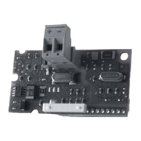
EVDMU**(R/N)** - Modulo ultracap per EVD ice/mini - Ultracap module for EVD ice/minic
+050004169 - rel. 1.0 - 18.10.2016
I moduli Ultracap per EVD ice/mini sono
dei dispositivi opzionali che permettono
di completare rispettivamente i driver
EVD ice/mini con un modulo di backup
esterno per la chiusura della valvola di
espansione elettronica unipolare, nel
caso di mancanza di alimentazione
elettrica. Il modulo Ultracap per EVD
mini va montato in un quadro elettrico,
mentre il modulo Ultracap per EVD
ice, dotato di grado di protezione IP67,
può essere montato direttamente
nell’evaporatore.
Ultracap per EVD mini
Ultracap per EVD ice
Ultracap for EVD mini
Ultracap for EVD ice
The Ultracap modules for EVD ice/mini
are optional devices that complete the
EVD ice/mini drivers respectively with an
external backup module for closing the
unipolar electronic expansion valve in
the event of power failures. The Ultracap
module for EVD mini is mounted in
an electrical panel, while the Ultracap
module for EVD ice, completed with
IP67 protection, can be installed directly
on the evaporator.
Attenzione: Il modulo Ultracap per EVD
ice si può installare solo con driver EVD ice
dotati del cavo di collegamento predisposto,
con i codici in tabella
Important:
The Ultracap module for EVD
ice can only be installed on EVD ice drivers
ready with the connection cable tted, with
the P/Ns listed in the table
DESCRIZIONE
DIMENSIONI - mm(in)
DESCRIPTION
DIMENSIONS - mm(in)
NO POWER
& SIGNAL
CABLES
TOGETHER
READ CAREFULLY IN THE TEXT!
Moduli ultracap Moduli ultracap
Cod. Descrizione Description
EVDMU**R** Modulo ultracap per EVD ice,
da installare con
Ultracap module for EVD ice, to
be installed with
EVDM011R1*
EVD ice, alimentazione
115/230 V, statore E2V,
display, connettore Ultracap
EVD ice, 115/230 V
power supply, E2V stator,
display, Ultracap connector
EVDM011R2*
EVD ice, alimentazione
115/230 V, statore E3V,
display, connettore Ultracap
EVD ice, 115/230 V
power supply, E3V stator,
display, Ultracap connector
EVDMU**N** Modulo ultracap per EVD mini Ultracap module for EVD mini
87,8 (3,5)
98,1 (3,9)
55 (2,2)
61,8 (2,4) 200 (7,9)
52 (2,0)
ø 2,2 (0,1)
88 (3.5)
98.1 (3.9)
ø 4.5 (0.2)
55 (2.2)
75 (3) 100(3.9) (±5%)
MONTAGGIO MOUNTING
Attenzione:
Il montaggio del modulo Ultracap
per EVD ice può essere eettuato
sopra il driver EVD ice (Fig.3), in modo
da minimizzare lo spazio occupato
dall’assieme e da lasciare visibili e
accessibili display e tastiera. Le quote
indicate nella dima di foratura (Fig.2) si
riferiscono a questo tipo di montaggio.
Important:
The Ultracap module for EVD ice can
be assembled on top of the EVD ice
driver (Fig. 3), so as to minimise the
space occupied and leave the display
and keypad visible and accessible.
The distances shown on the drilling
template (Fig. 2) refer to this type of
assembly.
Segnare sulla parete interna
dell’unità evaporatore le
posizioni dei fori secondo la dima
di foratura (g. 2) ed eseguirli (Ø
<4.5 mm). Avvitare quindi le viti
di ssaggio;
On the inside wall of the
evaporator unit, mark the
positions shown on the drilling
template (Fig. 2) and drill the
holes (Ø <4.5 mm). Then tighten
the fastening screws;
Per EVD ice: togliere il cappuccio
(A, g. 4) del cavo proveniente dal
driver, inserire completamente
il connettore proveniente dal
modulo Ultracap no a udire
“click”.
Per EVD mini: inserire il cavo di
collegamento con i connettori
JST nelle 2 schede (g.5).
For EVD ice: remove the cap
(A, Fig. 4) on the cable from the
driver, plug in the connector from
the Ultracap module fully, until
hearing a “click”.
For EVD mini: plug in the
connection cable with the JST
connectors on the two boards
(Fig. 5).
1
EVD ice
2
1
EVD ice
2click !
from EVD ice
from ULTRACAP module
1
2
3
A
Fig. 3
GAS Type
Mode
Super Heat
S1
S2
Ultracap
for EVD mini
EVD mini
Fig. 5
3.9(0.2)
3.9(0.2)
61.3(2.4) 45.5(1.8) 52.5(2.1)
55 (2.2)
88
(3.5)
98.1
(3.9)
79.4
(3.1)
92.4
(3.6)
85.6 (3.4) 73.7 (2.9)
FUNZIONAMENTO OPERATION
Nota:
Important:
• per la descrizione dettagliata della
procedura di chiusura di emergenza
valvola, consultare il manuale
cod.+0300038IT.
• for a detailed description of the
emergency valve closing procedure,
see manual +0300038EN.
I moduli garantiscono l’alimentazione
temporanea al driver in caso di
mancanza di tensione di alimentazione,
per il tempo sufficiente alla chiusura
immediata della valvola elettronica
connessa ad esso. Il loro utilizzo
permette di evitare quindi l’installazione
della valvola solenoide sulla linea del
liquido.
These modules guarantee temporary
power to the driver in the event of
a power failure, for sufficient time to
immediately close the connected
electronic valve. This thus avoids the
need to install a solenoid valve in the
refrigerant line.
Ultracap per/for EVD ice Ultracap per/for EVD mini
Fig. 1
Fig. 4
Fig. 2
CAREL INDUSTRIES HQs
Via dell’Industria, 11 - 35020 Brugine - Padova (Italy)
Tel. (+39) 0499716611 – Fax (+39) 0499716600
e-mail: [email protected] – www.carel.com
+050004169 - rel. 1.0 - 18.10.2016
I moduli sono realizzati tramite condensatori tampone (EDLC=Electric Double Layer
Capacitor), la cui ricarica è gestita autonomamente dai moduli stessi. I condensatori
EDLC assicurano un’affidabilità in termini di vita componente molto più lunga
rispetto ad un modulo realizzato con batteria al piombo: la vita stimata del modulo
UltraCap è di 10 anni. Inoltre non utilizzando batterie al piombo non richiede
particolari avvertenze in termini di sicurezza e procedure di smaltimento.
Nota importante
Quando avviene la chiusura di emergenza, i condensatori si scaricano
completamente. Quindi la carica assicura una sola chiusura della valvola. Al ritorno
dell’alimentazione i condensatori iniziano a ricaricarsi, è necessario quindi un
certo tempo, prima di poter garantire una nuova chiusura in caso di black-out. E’
necessario quindi assicurarsi che nel controllo macchina (es. c.pCO) sia impostato un
ritardo di accensione compressore, dopo il power-on, di almeno 4 minuti. In questo
modo è garantito dal controllo macchina che la valvola rimanga chiusa per tutto il
tempo necessario alla ricarica del modulo Ultracap.
CARATTERISTICHE TECNICHE
Condizioni di funzionamento -30T60 ˚C, < 90% U.R. non condensante
Condizioni di immagazzinamento -35T60 ˚C, < 90% U.R. non condensante
Grado di protezione EVDMU**R**: IP65/IP67; EVDMU**N**: IP00
Montaggio EVDMU**R**: con viti: sopra driver EVD
ice o a fianco. Cablaggio con connettore
Superseal che garantisce la protezione IP65;
EVDMU**N**: con viti a fianco del driver
Caratt. meccaniche
Dimensioni Vedere figure
Caratt. elettriche
Alimentazione per carica da diver EVD ice/ EVD mini (13Vdc)
Tempo di carica 4 minuti
Numero di azionamenti chiusura valvola
consecutivi in funzionamento tampone
1
Tensione di uscita 12 Vdc ± 15%
Classe di isolamento III
Protezione contro le scosse elettriche da integrare in apparecchiature di classe
III e/o II
Grado di inquinamento ambientale 2
Temperatura per prova filo incandescente 850°C
Immunità contro le sovratensioni categoria II
Altre caratteristiche
Conformità Sicurezza elettrica:
• EN 60730-1, UL 60730-1, UL 60730-2-9
Compatibilità elettromagnetica:
• EN 61000-6-1, EN 61000-6-2, EN 61000-6-3,
EN 61000-6-4
• EN61000-3-2, EN55014-1, EN61000-3-3
FUNZIONAMENTO CONT.
The modules are made using storage capacitors (EDLC=Electric Double Layer
Capacitor), which are recharged independently by the modules. EDLC capacitors
ensure reliability in terms of much longer component life than a module made
with lead batteries: the estimated life of the Ultracap module is at least 10 years. In
addition, not using lead batteries also means no special precautions are required
regarding safety and disposal.
Important note
When emergency closing occurs, the capacitors discharge completely. Consequently
the charge can only ensure one valve closing operation. When power returns the
capacitors start recharging, meaning a certain amount of time is needed before
being able to guarantee another closing operation in the event of blackout. As a
result, make sure that the control unit (e.g. c.pCO) is set with a compressor start
delay after power-on of at least 4 minutes. This guarantees that the valve remains
closed for the entire time needed to recharge the Ultracap module.
TECHNICAL CHARACTERISTICS
Operating conditions -30T60 ˚C, < 90% RH non-condensing
Storage conditions -35T60 ˚C, < 90% RH non-condensing
Ingress protection EVDMU**R**: IP65/IP67; EVDMU**N**: IP00
Installation EVDMU**R**: with screws: on the EVD ice
driver or alongside. Wiring with Superseal
connector to guarantee IP65 protection;
EVDMU**N**: with screws next to driver
Mechanical features
Dimensions See figures
Electrical features
Charge power supply from EVD ice/ EVD mini diver (13 Vdc)
Charge time 4 minutes
Number of consecutive valve closing
operations in backup mode
1
Output voltage 12 Vdc ± 15%
Insulation class III
Protection against electric shock to be integrated into class III and/or II
equipment
Environmental pollution 2
Temperature for glow wire test 850°C
Overvoltage category category II
Other features
Conformity Electrical safety:
• EN 60730-1, UL 60730-1, UL 60730-2-9
Electromagnetic compatibility:
• EN 61000-6-1, EN 61000-6-2, EN 61000-6-3,
EN 61000-6-4
• EN61000-3-2, EN55014-1, EN61000-3-3
OPERATION CONT.
NO POWER
& SIGNAL
CABLES
TOGETHER
READ CAREFULLY IN THE TEXT! ATTENZIONE: separare quanto più possibile i cavi delle sonde e degli ingressi
digitali dai cavi dei carichi induttivi e di potenza per evitare possibili disturbi elettromagnetici.
Non inserire mai nelle stesse canaline (comprese quelle dei quadri elettrici) cavi di potenza
e cavi di segnale.
ATTENZIONI IMPORTANTI: Il prodotto CAREL è un prodotto avanzato, il cui
funzionamento è speci cato nella documentazione tecnica fornita col prodotto o scaricabile,
anche anteriormente all’acquisto, dal sito internet www.carel.com. Il cliente (costruttore,
progettista o installatore dell’equipaggiamento  nale) si assume ogni responsabilità
e rischio in relazione alla fase di con gurazione del prodotto per il raggiungimento dei
risultati previsti in relazione all’installazione e/o equipaggiamento  nale speci co. La
mancanza di tale fase di studio, la quale è richiesta/indicata nel manuale d’uso, può generare
malfunzionamenti nei prodotti  nali di cui CAREL non potrà essere ritenuta responsabile.
Il cliente  nale deve usare il prodotto solo nelle modalità descritte nella documentazione
relativa al prodotto stesso. La responsabilità di CAREL in relazione al proprio prodotto è
regolata dalle condizioni generali di contratto CAREL presenti nel sito www.carel.com e/o
da speci ci accordi con i clienti.
SMALTIMENTO DEL PRODOTTO: l’apparecchiatura (o il prodotto) deve essere
oggetto di raccolta separata in conformità alle vigenti normative locali in materia
di smaltimento
NO POWER
& SIGNAL
CABLES
TOGETHER
READ CAREFULLY IN THE TEXT! WARNING: separare quanto più possibile i cavi delle sonde e degli ingressi
digitali dai cavi dei carichi induttivi e di potenza per evitare possibili disturbi elettromagnetici.
Non inserire mai nelle stesse canaline (comprese quelle dei quadri elettrici) cavi di potenza
e cavi di segnale.
IMPORTANT WARNINGS: The CAREL product is a state-of-the-art device, whose
operation is speci ed in the technical documentation supplied with the product or can
be downloaded, even prior to purchase, from the website www.carel.com. The customer
(manufacturer, developer or installer of the  nal equipment) accepts all liability and risk
relating to the con guration of the product in order to reach the expected results in relation
to the specic nal installation and/or equipment. The failure to complete such phase, which
is required/indicated in the user manual, may cause the  nal product to malfunction; CAREL
accepts no liability in such cases. The customer must use the product only in the manner
described in the documentation relating to the product. The liability of CAREL in relation to
its products is speci ed in the CAREL general contract conditions, available on the website
www.carel.com and/or by speci c agreements with customers.
DISPOSAL OF THE PRODUCT: The appliance (or the product) must be disposed of
separately in accordance with the local waste disposal legislation in force.
Other Carel Control Unit manuals

Carel EVD0000UC0 User manual

Carel

Carel EVD0000UC0 User manual

Carel E2V-C User manual

Carel

Carel E2V-C User manual

Carel PlantWatch User manual

Carel

Carel PlantWatch User manual

Carel EVD0000UC0 User manual

Carel

Carel EVD0000UC0 User manual

Carel ir33 DIN User manual

Carel

Carel ir33 DIN User manual

Carel UltraCella User manual

Carel

Carel UltraCella User manual

Carel EVD ice User manual

Carel

Carel EVD ice User manual

Carel FLSTDMFC0A User manual

Carel

Carel FLSTDMFC0A User manual

Carel PCOS00KX Series User manual

Carel

Carel PCOS00KX Series User manual

Carel Ultra 3PH User manual

Carel

Carel Ultra 3PH User manual

Carel E3V Series User manual

Carel

Carel E3V Series User manual

Carel uRack User manual

Carel

Carel uRack User manual

Carel PCOS00KXN0 User manual

Carel

Carel PCOS00KXN0 User manual

Carel E2V S0 Series User manual

Carel

Carel E2V S0 Series User manual

Carel MCH200TSV0 User manual

Carel

Carel MCH200TSV0 User manual

Carel WM00E-00 Series User manual

Carel

Carel WM00E-00 Series User manual

Carel E4V Series User manual

Carel

Carel E4V Series User manual

Carel E5V User manual

Carel

Carel E5V User manual

Carel E2V User manual

Carel

Carel E2V User manual

Carel Heosbox User manual

Carel

Carel Heosbox User manual

Carel E2V-U User manual

Carel

Carel E2V-U User manual

Carel PCOUMID200 User manual

Carel

Carel PCOUMID200 User manual

Carel ir33 Universale User manual

Carel

Carel ir33 Universale User manual

Carel uC2SE User manual

Carel

Carel uC2SE User manual

Popular Control Unit manuals by other brands

Harvia sentiotec Pro-C3 Instructions for installation and use

Harvia

Harvia sentiotec Pro-C3 Instructions for installation and use

BERGER WDP3-01X Safety instructions

BERGER

BERGER WDP3-01X Safety instructions

Eurolube 53430 manual

Eurolube

Eurolube 53430 manual

Burkert 2100 series operating instructions

Burkert

Burkert 2100 series operating instructions

Visonic PowerMax Pro GSM installation instructions

Visonic

Visonic PowerMax Pro GSM installation instructions

Phoenix Mecano Dewert Okin SG 300 installation instructions

Phoenix Mecano

Phoenix Mecano Dewert Okin SG 300 installation instructions

Emerson CSI 6500 quick start guide

Emerson

Emerson CSI 6500 quick start guide

ESD CAN-CBM-AI410 Hardware manual

ESD

ESD CAN-CBM-AI410 Hardware manual

TELink 825X user manual

TELink

TELink 825X user manual

M-system R7HL-TS4 instruction manual

M-system

M-system R7HL-TS4 instruction manual

System Sensor CR-6 Installation and Maintenance

System Sensor

System Sensor CR-6 Installation and Maintenance

National Instruments NI 9269 Getting started guide

National Instruments

National Instruments NI 9269 Getting started guide

S+S Regeltechnik Rymaskon 600 operating instructions

S+S Regeltechnik

S+S Regeltechnik Rymaskon 600 operating instructions

NETGEAR ProSecure UTM9SWLSN installation guide

NETGEAR

NETGEAR ProSecure UTM9SWLSN installation guide

Opentrons GEN1 instruction manual

Opentrons

Opentrons GEN1 instruction manual

Honeywell PRO4200 installation guide

Honeywell

Honeywell PRO4200 installation guide

EKE-Electronics EKE-Trainnet MVB2791B Technical manual

EKE-Electronics

EKE-Electronics EKE-Trainnet MVB2791B Technical manual

Dometic GROUP WAECO MagicSpeed MS-BE3 Installation and operating manual

Dometic GROUP

Dometic GROUP WAECO MagicSpeed MS-BE3 Installation and operating manual

manuals.online logo
manuals.online logoBrands
  • About & Mission
  • Contact us
  • Privacy Policy
  • Terms and Conditions

Copyright 2025 Manuals.Online. All Rights Reserved.