HENNESSY INDUSTRIES Coats HIT 5000 User manual

1601 J. P. Hennessy Drive, LaVergne, TN USA 37086-3565 615/641-7533 800/688-6359 Manual Part No.: 8109440 02
HENNESSY INDUSTRIES INC. Manufacturer of AMMCO®, COATS®and BADA®Automotive Service Equipment and Tools. Revision: 01/02
H.I.T. 5000
TRUCKTIRE CHANGER
®
Installation Instructions
Operating Instructions
Safety Instructions
Maintenance Instructions
READ these instructions before placing unit in
service KEEP these and other materials delivered
with the unit in a binder near the machine for
ease of reference by supervisors and operators.

ii • COATS H.I.T. 5000 Changer
Safety

COATS H.I.T. 5000 Changer • iii
Table of Contents
Operator Protective Equipment . . . . . . . . . . . . . . . . . . . . . . . . . . . . . . . . . . . . . . . . . . . .iv
Definitions of Hazard Levels . . . . . . . . . . . . . . . . . . . . . . . . . . . . . . . . . . . . . . . . . . . . . . .iv
Safety Instructions
Bead Loosening . . . . . . . . . . . . . . . . . . . . . . . . . . . . . . . . . . . . . . . . . . . . . . . . . . . . . .v
Demounting & Mounting . . . . . . . . . . . . . . . . . . . . . . . . . . . . . . . . . . . . . . . . . . . . . . .v
Inflation . . . . . . . . . . . . . . . . . . . . . . . . . . . . . . . . . . . . . . . . . . . . . . . . . . . . . . . . . . . . .v
Installation . . . . . . . . . . . . . . . . . . . . . . . . . . . . . . . . . . . . . . . . . . . . . . . . . . . . . . . . . . . .vi
Electrical Installation . . . . . . . . . . . . . . . . . . . . . . . . . . . . . . . . . . . . . . . . . . . . . . . . . . . .vi
Principal Operating Parts
Specificatons . . . . . . . . . . . . . . . . . . . . . . . . . . . . . . . . . . . . . . . . . . . . . . . . . . . . . . . .1
Wheel Clamping . . . . . . . . . . . . . . . . . . . . . . . . . . . . . . . . . . . . . . . . . . . . . . . . . . . . . . . .2
Tubeless, Duplex, and Supersingle Tires
Bead Loosening . . . . . . . . . . . . . . . . . . . . . . . . . . . . . . . . . . . . . . . . . . . . . . . . . . . . . .3
Demounting . . . . . . . . . . . . . . . . . . . . . . . . . . . . . . . . . . . . . . . . . . . . . . . . . . . . . . .3 - 4
Mounting . . . . . . . . . . . . . . . . . . . . . . . . . . . . . . . . . . . . . . . . . . . . . . . . . . . . . . . . . . .4
Wheels with Lock Rings
Bead Loosening and Demounting . . . . . . . . . . . . . . . . . . . . . . . . . . . . . . . . . . . . . . . .5
Mounting . . . . . . . . . . . . . . . . . . . . . . . . . . . . . . . . . . . . . . . . . . . . . . . . . . . . . . . . . . .5
Farm Tires
Bead Loosening . . . . . . . . . . . . . . . . . . . . . . . . . . . . . . . . . . . . . . . . . . . . . . . . . . . . . .6
Demounting . . . . . . . . . . . . . . . . . . . . . . . . . . . . . . . . . . . . . . . . . . . . . . . . . . . . . . .6 - 7
Mounting . . . . . . . . . . . . . . . . . . . . . . . . . . . . . . . . . . . . . . . . . . . . . . . . . . . . . . . . . . .7
Tire Spreading
Method A: . . . . . . . . . . . . . . . . . . . . . . . . . . . . . . . . . . . . . . . . . . . . . . . . . . . . . . . . . . .8
Method B: . . . . . . . . . . . . . . . . . . . . . . . . . . . . . . . . . . . . . . . . . . . . . . . . . . . . . . . . . . .8
Maintenance . . . . . . . . . . . . . . . . . . . . . . . . . . . . . . . . . . . . . . . . . . . . . . . . . . . . . . . . . . .9
TruckTire Changer Warranty Policy . . . . . . . . . . . . . . . . . . . . . . . . . . . . . . . . . . . . . . .Back
Service Policy . . . . . . . . . . . . . . . . . . . . . . . . . . . . . . . . . . . . . . . . . . . . . . . . . . . . . . . .Back
Contents

iv • COATS H.I.T. 5000 Changer
Safety
Failure to follow danger, warning, and caution
instructions may lead to serious personal injury or
death to operator or bystander or damage to prop-
erty. Do not operate this machine until you read
and understand all the dangers, warnings and cau-
tions in this manual. For additional copies of either,
or further information, contact:
Hennessy Industries, Inc.
1601 J.P. Hennessy Drive
LaVergne, TN 37086-3565
(615) 641-7533 or (800) 688-6359
www.ammcoats.com
Operator Protective
Equipment
Personal protective equipment helps make tire serv-
icing safer. However, equipment does not take the
place of safe operating practices. Always wear durable
work clothing during tire service activity. Loose fitting
clothing should be avoided. Tight fitting leather gloves
are recommended to protect operator’s hands when
handling worn tires and wheels. Sturdy leather work
shoes with steel toes and oil resistant soles should be
used by tire service personnel to help prevent injury in
typical shop activities. Eye protection is essential dur-
ing tire service activity. Safety glasses with side
shields, goggles, or face shields are acceptable. Back
belts provide support during lifting activities and are
also helpful in providing operator protection.
Consideration should also be given to the use of hear-
ing protection if tire service activity is performed in an
enclosed area, or if noise levels are high.
Definitions of Hazard
Levels
Identify the hazard levels used in this manual with
the following definitions and signal words:
DANGER
Watch for this symbol:
It Means: Immediate hazards, which will result in
severe personal injury or death.
WARNING
Watch for this symbol:
It Means: Hazards or unsafe practices, which could
result in severe personal injury or death.
CAUTION
Watch for this symbol:
It Means: Hazards or unsafe practices, which may
result in minor personal injury or product or property
damage.
Watch for this symbol! It means BE ALERT! Your
safety, or the safety of others, is involved!
CAUTION
WARNING
DANGER
WARNING
WARNING
Read entire manual
before assembling,
installing, operating,
or servicing this
equipment.

COATS H.I.T. 5000 Changer • v
Safety Instructions
Only properly trained personnel should
service tires on the H.I.T. 5000. Read all
safety and operating instructions thor-
oughly before using the tire changer.
ALWAYS remove all wheel weights and the valve
core to deflate the tire before servicing.
ALWAYS cover the electric motor and switch box
before hosing down the tire changer. Be sure water
does not enter the motor or switch box.
ALWAYS disconnect the electric power and air sup-
ply before attempting any maintenance.
ALWAYS keep all working surfaces clean and free of
tire lube buildup.
ALWAYS be aware of what each person is and will do
before attempting any two-person operation.
Bead Loosening
NEVER place anything between the bead loosener
disc and the tire/wheel.
NEVER place any part of your body between the
bead loosener disc and the tire/wheel, severe bodily
injury may result.
NEVER allow the bead loosener to contact the
wheel, wheel damage may occur.
Demounting & Mounting
NEVER stand on the working table while demount-
ing or mounting a tire.
ALWAYS keep hands, feet, and other objects away
from moving parts while the machine in turned on.
ALWAYS place the narrow bead seat to the outside
when clamping. Failure to demount the tire from the
narrow bead seat side may cause damage to the tire
beads.
ALWAYS apply an approved rubber lubricant to rim
flanges and both tire beads before demounting or
mounting and seating the beads. NEVER use
antifreeze, silicone, or petroleum base lubricants.
ALWAYS clean and inspect the wheel.
NEVER mount a tire on a damaged or rusty wheel.
Wheel damage or rust may cause tire or wheel failure
during inflation. Explosion from failure may result in
severe injury or death of the operator and bystanders.
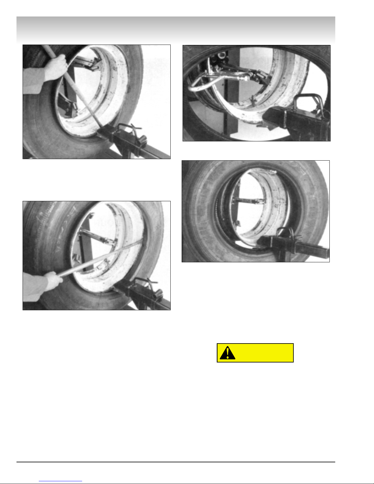
ALWAYS be sure the bead opposite the tool is in the
drop center before rotating the tire when demounting
or mounting to avoid damage to the tire beads.
Inflation
ALWAYS follow all applicable Local, State, and
Federal Codes, Rules, and Regulations; such as the
Federal OSHA Standard Number 1910.177.
NEVER seat beads or inflate a tire on the tire
changer. The H.I.T. 5000 is not designed as a safety
device or stand for bead seating or inflation.
ALWAYS use an approved inflation chamber or infla-
tion cage.
The following safety instructions are for one piece
wheels only. Refer to the manufacturer’s or R.M.A.
procedures for multipiece wheels.
ALWAYS use an approved inflation chamber or infla-
tion cage equipped with a grip chuck and a remote
inflation gauge and valve. DO NOT OVER INFLATE!
Tire or wheel failure during and after inflation may
result in an explosion capable of causing severe injury
or death.
ALWAYS inflate the tire to manufacturer’s recom-
mended cold operating pressure.
NEVER reinflate a tire that has been run underin-
flated or flat without first demounting the tire and
checking for wheel and tire damage.
ALWAYS inspect the tire interior for loose or broken
cords, cuts, penetrating objects, and other damage to
the carcass. Discard tires that cannot be properly
repaired.
NEVER rework, weld, heat or braze wheels.
NEVER strike the tire or wheel with a hammer.
ALWAYS be sure the tire diameter exactly matches
the wheel diameter.
Tire failure under pressure can be haz-
ardous. Place the wheel inside an approved
inflation chamber or cage before inflating.
Use an approved remote inflation valve,
hose, and gauge. ALWAYS wear safety gog-
gles for eye protection. Do not stand beside
the wheel or cage during inflation. Keep
hands and other parts of the body out of
the cage during inflation. Observe the tire
pressure frequently. Do not exceed the
manufacturer’s recommended maximum
inflation pressure. Failure to follow these
instructions may cause the tire and rim to
separate with tremendous force, resulting
in serious personal injury or death.
DANGER
WARNING
Safety

vi • COATS H.I.T. 5000 Changer
H.I.T. 5000
Installation
It is not necessary to bolt the H.I.T. 5000 to the floor.
However, if desired, use the holes provided in the
base of the machine.
Most electrical codes require machinery
that is permanently installed to be wired
directly to the power source via conduit.
Remove the H.I.T. 5000 from the shipping pallet and
position on a relatively level and smooth floor, prefer-
ably concrete.
Important: Read this operators manual thoroughly
before attempting to change any tires. Also, actuate
the controls several times to become familiar with
their function and direction.
Electrical Installation
The H.I.T. 5000 requires 220 volts, 60 cycle, single
phase power, with a 20 amp circuit. An optional model
is available for 110 volt, single phase.
Important: Have a licensed electrician connect the
H.I.T. 5000 to the power source. The licensed electri-
cian must sign the warranty registration card to vali-
date the warranty.
CAUTION

COATS H.I.T. 5000 Changer • 1
Principal Operating Parts
Specifications
Working Area: 10 Foot Wide x 10Foot Long x 8 Foot Height
Weight: 1,400 Pounds
Handles Tires: Truck - 16 Inches to 24.5 Inches Tube-type and Tubeless
Grader, Industrial and Farm - 16 Foot to 42 Inches
H.I.T. 5000

Wheel Clamping
The self-centering chuck is powered by the high pres-
sure hydraulic system to securely lock onto the wheel.
Important: The hydraulic pressure regulator knob,
located on the swinging pod front, should normally be
set to 1500 PSI.This pressure should be reduced when
mounting or demounting weak or light weight wheels.
1. Roll the wheel onto the platform with the drop
center (or the split ring) away from the chuck. Position
the valve stem between two of the jaw clamps so the
stem will not be damaged when the wheel is clamped.
2. Rotate the chuck until one of the jaw clamps is in
the 12 o'clock position.
3. Open the jaw clamps slightly larger than the open-
ing you are clamping, then move the jaw clamps up or
down to the approximate center of the wheel. Refer to
the wheel drawings on this page for suggested meth-
ods of clamping various types of wheels.
4. Lower the jaw clamps until you can position the
wheel on the top jaw clamp. Raise the chuck, which
will also raise the wheel off the platform.
5. Slowly retract the jaw clamps until the wheel falls
into the proper position for clamping. Clamp the wheel
by pulling the control lever toward you until the
hydraulic motor stalls. Release the handle and the
wheel is ready for mounting or demounting.
H.I.T. 5000
2 • COATS H.I.T. 5000 Changer

H.I.T. 5000
COATS H.I.T. 5000 Changer • 3
Bead Loosening
1. After locking the wheel on the chuck, remove the
valve core and deflate the tire completely.
2. Position the bead loosening disc in one of the
square holes in the carriage closest to the outer edge
of the tire.
3. Rotate the tire. While the tire is rotating, slowly
advance the bead loosening disc to contact the tire
bead. Adjust the chuck up or down so the disc is close
to the rim.
Do not contact the rim with the bead loos-
ening disc. Damage to the rim may result.
4. Once the rim edge is cleared, the chuck may be
lowered to move the disc closer to the tire bead.
Continue moving the disc toward the machine until the
bead is loosened.
5. While the tire is still rotating, apply a liberal
amount of tire lubricant to the tire bead and the rim.
6. Raise the chuck and back the tool away from the
tire, being careful not to contact the rim.
7. Move the bead loosening disc to the rear of the
tire and repeat the steps above to loosen the rear
bead.
Note: Tire lubricant is very important in the demount-
ing and mounting process. While the bead loosening
tool is pushing the bead away from the rim edge, lib-
erally lube both beads and the rim. FAILURE TO APPLY
LUBE COULD RESULT IN DAMAGE TO THE TIRE
BEAD.
Note: Applying a liberal amount of lube to the tire
sidewall prior to bead loosening will make the tire
more pliable and therefore reduce the likelihood of
damage to the sidewall.
Demounting
1. If the rim has an inclined edge of 15 degrees, con-
tinue the bead loosening procedure for the rear bead
until the tire has been pushed off the rim.
The bead opposite the disc must be in the
drop center of the rim. Damage to the bead
may occur if the bead is not in the drop cen-
ter.
2. If the rim has no edge, or has a stiff sidewall,
retract the disc and remove it from the carriage. Place
the combo tool and tee into position near the outer rim
edge.
CAUTION
CAUTION
Tubeless, Duplex, and Supersingle Tires

3. Tighten the locking handle and move the tool into
position near the edge of the rim, as shown above.
4. Insert the bead lifting tool between the rim and
bead at a point near the right side of the tool.
5. Pry the bead out over the rim. Note:You may have
to assist the bead opposite the tool into the drop cen-
ter. Use one of the tire tools to pry the top bead into
the drop center.
6. Rotate the wheel counterclockwise while main-
taining pressure on the bead lifting tool until the first
bead is off.
7. Repeat the steps above for the rear bead.
8. Retract the tool and remove the tire.
Mounting
1. LUBE BOTH BEADS LIBERALLY.
2. Roll the tire onto the carriage and lean it back
against the rim.
3. Position the combo tool near the edge of the rim
as shown. DO NOT CONTACT THE RIM.
4. Securely clamp the vise grip to the rim edge at a
position to the left of the combo tool. Rotate the chuck
clockwise until the vise grip hooks the inner bead and
lifts the tire.
5. Continue rotating the chuck until the first bead is
mounted. Avoid rotating the vise grip into the
combo tool.
6. Remove the vise grip and repeat the steps above
to mount the outer bead.
When mounting a tire, the bead must be
started in the drop center of the rim. Failure
to use the drop center could result in dam-
age to the tire bead.
Note: It may be necessary to push the bead(s) into
the drop center during the mounting process.
Note: Tire lubricant greatly reduces the force needed
to demount or mount a tire. Liberally lube each bead
and rim edge while the bead loosener disc holds the
bead away from the rim. FAILURE TO APPLY LUBE
COULD RESULT IN DAMAGE TO THE TIRE BEADS.
CAUTION
H.I.T. 5000
4 • COATS H.I.T. 5000 Changer

H.I.T. 5000
COATS H.I.T. 5000 Changer • 5
Bead Loosening and Demounting
1. After chucking the wheel, position the bead
loosener disc against the sidewall within 1/4 inch of the
lock ring. Do not contact the ring.
2. Rotate the wheel and slowly advance the bead
loosener disc until the bead is loosened. LIBERALLY
LUBE THE TIRE BEAD AND RIM.
3. Use the ring tool to remove the lock ring(s).
4. Raise the tire and move the bead loosening disc
into position on the inner bead. Do not contact the rim.
5. Rotate the wheel and slowly advance the disc to
push the tire about half way off the wheel. Push the
valve stem inside the wheel, then finish pushing the
tire off the wheel.
The tube will be damaged if the operator
fails to push the valve stem into the wheel
before completely removing the tire.
Mounting
1. Roll the tire onto the carriage, and align the rim to
the center of the tire.
2. Liberally lube both beads and the rim. Slowly
advance the carriage and guide the tire onto the rim.
Stop about 1/3 of the way on and insert the tube.
3. Place the bead loosening disc in the carriage.
Position it against the tire bead and push the tire onto
the rim.
4. With the disc pushing on the outer sidewall, install
the ring(s).
CAUTION
Wheels with Lock Rings

Bead Loosening
1. Remove the valve core. Deflate the tire away from
the machine and remove any calcium chloride or other
substances from the tire prior to rolling the wheel onto
the tire changer.
2. After locking the wheel on the chuck, move the
bead loosening disc into position near the edge of the
rim.
Note: Apply a liberal amount of lube to the tire side-
wall. This will regain some of the original flexibility of
the rubber, thus reducing possible damage to the side-
wall.
3. Rotate the wheel and slowly move the bead loos-
ening disc into the sidewall until the bead is loosened.
4. Continue to rotate the tire and apply a liberal
amount of lube to the bead and the rim.
5. Move the bead loosening tool to the inner bead
and repeat the above steps.
Note: Tire lubricant greatly reduces the force needed
to demount or mount a tire. Liberally lube each bead
and rim edge while the bead loosener disc holds the
bead away from the rim. FAILURE TO APPLY LUBE
COULD RESULT IN DAMAGE TO THE TIRE BEADS.
Demounting
1. Advance the combo tool close to the rim, with the
finger past the rim edge.
2. With the spade tool inserted between the rim and
the outer bead, on the right of the combo tool, pry the
bead out over the rim edge.
H.I.T. 5000
6 • COATS H.I.T. 5000 Changer
Farm Tires

H.I.T. 5000
COATS H.I.T. 5000 Changer • 7
3. Rotate the wheel counterclockwise while main-
taining pressure on the spade tool until the outer bead
is demounted. Push the valve stem inside the rim and
pull the inner tube out of the tire.
Note: It is possible to roll one or both beads(s) off the
rim with the bead loosener disc instead of the combo
tool. However, care must be taken not to damage the
tube or the valve stem. By alternately rotating the
wheel first counterclockwise, then clockwise, being
careful not to pass over the valve stem, the tire may be
demounted using this method. If the tire is wide, the
rim is thin or weak, or the side wall is tough, do not use
this method since the bead or the rim may be dam-
aged.
Note: Tire lubricant greatly reduces the force needed
to demount or mount a tire. Liberally lube each bead
and rim edge while the bead loosener disc holds the
bead away from the rim. FAILURE TO APPLY LUBE
COULD RESULT IN DAMAGE TO THE TIRE BEADS.
Mounting
1. Lube both beads and the rim liberally.
2. Rotate the rim so the valve stem hole is directly
on the bottom, then roll the wheel onto the carriage.
3. Move the combo tool into position near the edge
of the rim.
Note: Mounting of the outer bead is shown in order
to see the position of the tools. Position of the tools
will be the same for the inner bead.
4. Lean the tire against the rim and clamp the vise
grip on the edge of the rim to the left of the combo
tool. Rotate the chuck to lift off the carriage.
5. Using one of the tire tools to assist the bead into
drop center, continue rotating the chuck until the inner
bead is mounted.
6. Insert the inner tube and repeat the above steps
to mount the outer bead.
Note: Avoid damage to the valve stem by never
allowing the stem to pass the stationary tool.

There are two methods of spreading the tire with the
roller tool.
Method A:
1. With the first bead removed, hook the roller tool
over the outer bead and move the tool away from the
rim to spread the beads and gain access to the inside
of the tire.
Method B:
1. With the tire completely demounted and the rim
removed from the clamps, hook the inner bead over
the clamps and the roller tool over the outer bead.
Move the tool away from the inner bead to gain access
to the inside of the tire.
Tire Spreading
Note:The wheel can be rotated with the roller tool still in place,
but the tool should be moved toward the wheel slightly. This will
relieve some of the pressure on the bead, thus avoiding any
damage, which might occur from over stretching the bead.
Tire failure under pressure can be hazardous. Place
the wheel inside an approved inflation chamber or
cage before inflating. Use an approved remote infla-
tion valve, hose, and gauge. ALWAYS wear safety
goggles for eye protection. Do not stand beside the
wheel or cage during inflation. Keep hands and other
parts of the body out of the cage during inflation.
Observe the tire pressure frequently. Do not exceed
the manufacturer's recommended maximum infla-
tion pressure. Failure to follow these instructions
may cause the tire and rim to separate with tremen-
dous force, resulting in serious injury or death.
DANGER
H.I.T. 5000
8 • COATS H.I.T. 5000 Changer

H.I.T. 5000
COATS H.I.T. 5000 Changer • 9
1. Using a grease gun and chassis grease, lubricate
chuck hub bushing once every month.
2. Remove the side panels and lubricate the four
posts that guide the carriage up and down. Also, with
a grease gun, lubricate the bushing sprocket tube.
Lubricate these parts at lease once every month.
3. Using a grease gun and chassis grease, lubricate
the disk shaft on the bead roller tube once every
month.
4. Grease chain and check the tension once every
month and adjust if necessary.
5. Check hydraulic reservoir once every week. With
all hydraulic cylinders retracted, the oil level should be
approximately two inches below the top of reservoir.
Add COATS®hydraulic oil (P.N. 8120454) to this level.
6. Change the oil filter once every six months. Screw
off the filter and replace with service part number
8001631.
Maintenance

8109440 02 01/02 © Copyright 1997 Hennessy Industries and COATS®All Rights Reserved Printed in USA
Truck Tire Changer Warranty Policy
The COATS®Company warrants the H.I.T. 5000 Truck Tire Changer to be free of defects in workmanship and
material for a period of twelve (12) months from the date of installation. Labor will be covered by the COATS®
Company for a period of 90 days from the date of installation.
Upon inspection by COATS®Company or its authorized representative, any defect in workmanship and/or mate-
rial within the warranty period will be:
Replaced in the field by the user, parts supplied free of charge by the COATS®Company, LaVergne, Tennessee,
for the first 12 months of operation. Labor is covered by the COATS®Company for the first 90 days of operation.
This warranty is in lieu of all other warranties, expressed or implied, and of all other obligations and/or liabilities,
and no person is authorized to make any other representation or assume any other obligation on behalf of the
manufacturer.
This warranty shall not apply if damage is due to accident, negligence, alteration, abuse or misuse, worn parts,
installation by unlicensed electrician, or has not been operated in accordance with the manufacturer's instructions
for operation. Parts replaced under warranty will assume the remainder of the unit's warranty period. Only parts
and accessories manufactured by the COATS®Company will be warranted as stated above and this warranty shall
not apply to the tire changer or any parts thereof if parts and accessories not manufactured by COATS®Company
are used as replacements for or in substitution of COATS®Company manufactured parts and accessories.
To validate warranty:
1. A licensed electrician must install all electrical requirements and sign the attached warranty registration card.
2.The owner must fill out the post-paid warranty registration card and return it to COATS®Company within thirty
(30) days of installation.
Failure to perform 1 above will void warranty coverage on electrical and hydraulic components. Failure to perform
2 may void entire warranty.
Service Policy
Upon recognition of a problem, review the Maintenance Instructions and Service Manual.
If further assistance is required, call:
(800) 688-6359
or
your nearest
Hennessy Regional
Office
The COATS®Company will supply a replacement part-no charge- when it is determined by the factory or an
authorized representative that the part is defective in workmanship and/or material and is covered by the warranty
policy. The owner has the option to send the defective part to the COATS®Company for inspection, repair or
replacement. All returns to the factory must be authorized by the COATS®Company prior to return. Freight to the
factory will be paid by the owner. If the machine is serviced by COATS®authorized personnel, labor charges will
be covered for a period of 90 days after the date of installation.
Table of contents
Popular Automobile Accessories manuals by other brands

Whelen Engineering Company
Whelen Engineering Company SA315EKT installation guide

Gator
Gator G42V user manual

Hook
Hook E063 quick start guide

Whelen Engineering Company
Whelen Engineering Company Mini Edge Wiring & Part Replacement Guide

Nexcom
Nexcom VTC 1010 user manual

AFX MOTORSPORTS
AFX MOTORSPORTS DEF060 installation manual