HENNING LP User manual
Henning
GmbH
&
Co.
KG
Loher Str. 4
58332 Schwelm
Germany
fon: +49 2336 92 98-0
fax: +49 2336 92 98-100
nfo@henn ng-gmbh.de
www.henn ng-gmbh.de
www.henn ng-cnc.de
Operat ng Instruct ons Elevator Buffers LP Page 1 Ed t on 3.3.1 EN of 03.04.2017
Operating Instructions for Elevator Buffers type LP
Scope of application
The Elevator Buffer type LP s an energy dissipation type buffer accord ng to EN 81-1/2, EN 81-20, EN
81-50 5.5 and therefore can be un versally used for all appl cat ons n the construct on of elevators. The
EC type exam nat on perm ts the use n passenger and fre ght elevators both under the elevator car and
under the counter we ght.
2 Functional description
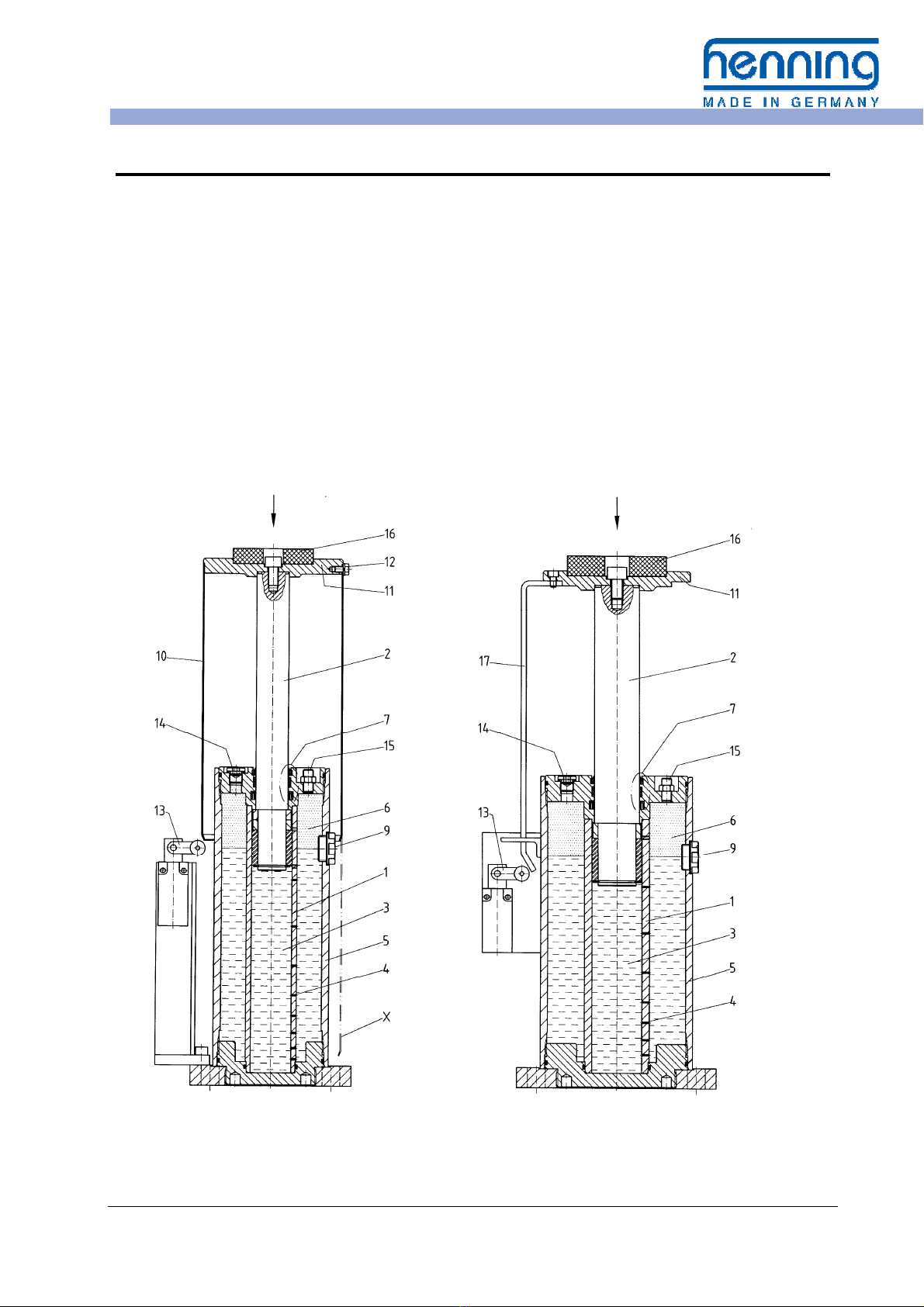
F g. 1a: Buffer w th Protect on Tube F g. 1b: Buffer w th L near Sl de

Henning
GmbH
&
Co.
KG
Loher Str. 4
58332 Schwelm
Germany
fon: +49 2336 92 98-0
fax: +49 2336 92 98-100
nfo@henn ng-gmbh.de
www.henn ng-gmbh.de
www.henn ng-cnc.de
Operat ng Instruct ons Elevator Buffers LP Page 2 Ed t on 3.3.1 EN of 03.04.2017
In the case of a buffer stroke the p ston rod 2 s
forced nto the cyl nder tube and the hydraul c
flu d 3 n the tube s d splaced and forced to the
outs de through small throttl ng ports 4 n the
tube wall. The flu d accumulates w th n the jack-
et tube 5.
At the same t me the gas volume 6 above the
hydraul c med um s further compressed. The
seal ng system 7 ma nta ns a rel able seal be-
tween the hard chrom um-plated p ston rod and
the atmosphere.
After the buffer stroke and return to hydraul c
balance the compressed gas volume forces the
d splaced flu d back nto the cyl nder and ex-
tends the p ston rod.
The level of the hydraul c flu d at the gas nter-
face can be read at any t me through the s ght
glass 9 w thout open ng the un t.
An elast c mpact plate 6 damps the mpact and
reduces the no se.
The l m t sw tch 3 mon tors the extended ready
pos t on of the buffer. The l m t sw tch s actuated
by pressure on the p ston rod by the l near sl de
7 or the protect on tube 0 respect vely.
In the case of buffers equ pped w th a protect on
tube 0, for ma ntenance work the screws 2 on
the buffer head are removed. Subsequently,
the protect on tube can be lowered, wh ch s mul-
taneously actuates the sw tch 3. The o l f ller
screw 4 and the gas-f ll ng valve 5 w ll then be
access ble.
In the normal operat ng state the protect on tube
avo ds damage and contam nat on of the p ston
rod.
3 General Instructions
If people are work ng n the elevator shaft a
su table refuge must be ensured.
For th s purpose the general safety nstruct ons
of the elevator manufacturer have to be ob-
served.
Warning!
Buffers are safety devices. Mounting, inspection and maintenance work
may only be carried out by expert personnel! Observe the
applicable safety instructions!
4 Preparations
4. Design Data
Among the data on the buffer type plate there s
ncluded:
• P ston d ameter and stroke
• M n mum mpact mass,
• Max mum mpact mass and
• Rated speed
4.2 Ambient Temperature Limit
The amb ent temperature should be between
-10 °C and 50 °C.
The buffer can be suppl ed n a spec al des gn
f lled w th a spec al hydraul c o l for low amb ent
The f rst check should be to ensure that the op-
erat ng cond t ons do not exceed th s des gn
data.
temperatures. Th s buffer can be used between
-20 °C and +40 °C and s labelled w th a spec al
des gnat on for th s temperature range. An en-
hanced EC type exam nat on s also prov ded.

Henning
GmbH
&
Co.
KG
Loher Str. 4
58332 Schwelm
Germany
fon: +49 2336 92 98-0
fax: +49 2336 92 98-100
nfo@henn ng-gmbh.de
www.henn ng-gmbh.de
www.henn ng-cnc.de
Operat ng Instruct ons Elevator Buffers LP Page 3 Ed t on 3.3.1 EN of 03.04.2017
4.3 Place of Installation
The place of nstallat on should be n a clean
and dry cond t on.
Ver fy the place of nstallat on of the buffer and
the bear ng capac ty of the mount ng surface.
Ver fy the s ze of the rema n ng lower refuge. For
an ent rely pressed- n elevator car buffer a suff -
c ently d mens oned refuge must be prov ded
below the elevator car n compl ance w th the
respect ve code.
The p ston rod should not be contam nated by
external mpact.
Dur ng operat on of the elevator t has to be en-
sured that the surface of the p ston rod s free of
adherences of snow and/ or ce and not frosted.
In case of d ssent ng operat on cond t ons,
please contact Henn ng GmbH & Co KG.
5 Mounting
!
Safety Instruction:
Prior to all mounting and maintenance work, an appropriate measure to prevent au-
tomatic switching on or automatic start-up of the drive must be in place!
1. The buffer s suppl ed ready for nstallat on
complete w th o l f ll ng.
2. If the buffer s suppl ed w th pressed- n p s-
ton rod, the secur ng dev ces should be re-
moved. Cut the secur ng straps at the s de
when the buffer s stand ng upr ght.
Warning! The extending piston rod can
cause injury!
3. Fasten ng mater al should be ordered sepa-
rately. Su table means are heavy-duty dow-
els or rag bolts M 16x160 DIN 529 w th nuts
and washers 18 DIN 126.
4. Fasten ng should be made n the upr ght
cond t on d rectly on the ground or on a su t-
able console. The buffer p ston rod should
be accurately mounted n the vert cal pos -
t on. Therefore, mount ng must be made on
a hor zontal surface or su table sh ms should
be used.
5. The buffer should be f xed exactly under the
centre of grav ty of the elevator car or coun-
terwe ght respect vely. If several buffers are
used, these must be d str buted symmetr -
cally to the centre. Check the al gnment of
the buffer e. g. us ng a water level. The p s-
ton rod has to po nt vert cal up.
6. Press- n the p ston rod several t mes by
hand. Th s perm ts transport-caused a r
bubbles to escape from the hydraul c flu d.
Subsequently, the p ston rod must be com-
pletely extended and the o l level correct.
If buffers may be d s-
placed for serv ce work
at the elevator e. g. by
1. The elevator may only be set nto operat on aga n f the buffer
s replaced to ts work ng pos t on and fastened correctly. We
recommend nstall ng a su table electr cal controll ng dev ce.
2. Then press- n the p ston rod of the buffer at least two t mes.
Th s allows a r bubbles escap ng from the hydraul c cyl nder.
3. F nally check, that the p ston rod s fully extended and the o l
level s correct.
4. F x su table nstruct ons for act ng near the po nt of nstallat on.
• sw ng ng to a serv ce pos t on
or
• remov ng
please note:
Henning
GmbH
&
Co.
KG
Loher Str. 4
58332 Schwelm
Germany
fon: +49 2336 92 98-0
fax: +49 2336 92 98-100
nfo@henn ng-gmbh.de
www.henn ng-gmbh.de
www.henn ng-cnc.de
Operat ng Instruct ons Elevator Buffers LP Page 4 Ed t on 3.3.1 EN of 03.04.2017
5. Electric Connection
Dangerous Voltage!
During connection work the installation must be de-energised!
Carry out the electr c connect on to the l m t
sw tch 3 (F gures 1a or 1b). Dur ng w r ng the
work ng range of the l near sl de 7 and the
protect on tube 0 dur ng buffer stroke must be
observed.
6 Commissioning
!
Safety Instruction:
During buffer testing no persons are allowed
to stay in the elevator shaft!
1. Ver fy the extended pos t on of the p ston
rod and the o l level.
2. Carry out a f rst buffer test w th reduced
speed and w thout add t onal load.
3. Ver fy the electr cal s gnal of l m t sw tch 13.
4. Wa t for approx. 1 - 2 m nutes and then re-
l eve the buffer.
5. Ver fy the extended pos t on of the p ston
rod and the o l level. Check the buffer and
the mpact po nt for poss ble damage and o l
leaks.
6. If no defects are found, carry out a second
buffer test. Th s test should be carr ed out, f
poss ble, w th rated speed and max mum
load.
7. Repeat po nts 4. and 5. .
If no defects are found, the buffer s ready for
operat on.
7 Regular inspections
Dur ng regular nspect ons of the elevator nstal-
lat on or for trouble shoot ng the follow ng
nspect ons are poss ble for wh ch all the a/m
safety nstruct ons must be observed:
7. Inspection of the extended piston rod
Buffer w th protect on tube to F g. 1a:
• The s ght glass 9 s not masked by the pro-
tect on tube 0.
• The l m t sw tch 3 s not actuated.
Buffer w th l near sl de to F g. 1b:
• The l m t sw tch 3 s not actuated.
• The v s ble part of the p ston rod s as long
as the respect ve stroke (see nd cat on on
the type plate).
Henning
GmbH
&
Co.
KG
Loher Str. 4
58332 Schwelm
Germany
fon: +49 2336 92 98-0
fax: +49 2336 92 98-100
nfo@henn ng-gmbh.de
www.henn ng-gmbh.de
www.henn ng-cnc.de
Operat ng Instruct ons Elevator Buffers LP Page 5 Ed t on 3.3.1 EN of 03.04.2017
7.2 Oil level check
The elevator buffers ser es LP are equ pped
w th a s ght glass as an o l nd cator. Therefore,
the buffer does not need to be opened for the o l
level check! Th s nspect on should only be car-
r ed out w th fully extended p ston rod (see a/m
po nt 7.1).
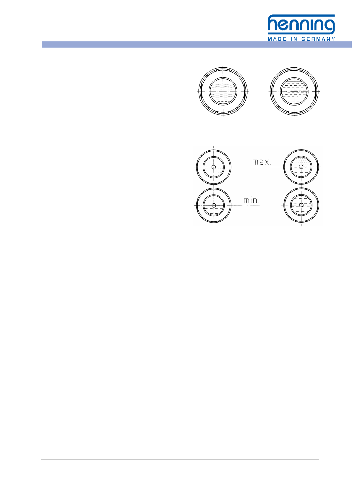
a) Buffer w th one s ght glass
The o l level should be v s ble n the
s ght glass 9, see F g. 2a
b) Buffer w th two s ght glasses
- m n mum: the o l level s v s ble n
the lower s ght glass
- max mum: the o l level s below the
top edge of the upper
s ght glass
see F g. 2b
Factory o l f ll ng for buffers w th one s ght glass
s up to the centre of the s ght glass (at amb ent
temperatures of 16 °C to 22 °C).
Factory o l f ll ng for buffers w th two s ght glass-
es s below the top edge of the upper s ght
glass.
The o l level s depend ng on temperature. At
amb ent temperatures around freez ng po nt, the
o l level can drop near the m n mum. H gh amb -
ent temperatures let the o l level r se.
If dur ng the o l level check the o l level s found
to be too h gh, a r bubbles m ght be n the o l. In
th s case f rst press the p ston rod of the (upr ght
stand ng) buffer several t mes as far as poss ble.
If the o l level s not fall ng although the p ston
rod s fully extended, o l must be removed.
If the o l level s too low, o l must be added (see
po nt 8.3 "Correct on of the o l level"). In th s
case check the buffer for leakage.
7.3 Gas pressure check
For resett ng the p ston rod after a buffer stroke
the buffer s f lled w th n trogen. The gas pres-
sure at extended p ston rod s 5 bar.
The gas pressure may be checked w thout us ng
a measur ng nstrument. For th s purpose press
the p ston rod by hand for some cent metres.
If the p ston rod then returns automat cally to ts
n t al pos t on, the gas pressure s suff c ent.
Otherw se proceed as descr bed under po nt 8.4
"Gas ref ll ng".
7.4 General visual inspection
Pay attent on to o l spots on the floor or on the
buffer. An o l f lm on the p ston rod 2 s normal.
Check the p ston rod surface for damage and
t ghtly adherent contam nat ons.
Check the state and funct on of the l m t
sw tch 3.
If leaks or damage s found, the buffer must be
exchanged or repa red.
O l level m n mum O l level max mum
F g. 2a: O l level nd cat on w th one s ght glass
O l level m n mum O l level max mum
F g. 2b: O l level nd cat on w th two s ght glasses
Henning
GmbH
&
Co.
KG
Loher Str. 4
58332 Schwelm
Germany
fon: +49 2336 92 98-0
fax: +49 2336 92 98-100
nfo@henn ng-gmbh.de
www.henn ng-gmbh.de
www.henn ng-cnc.de
Operat ng Instruct ons Elevator Buffers LP Page 6 Ed t on 3.3.1 EN of 03.04.2017
7.5 Check the piston rod for icing
If the buffer s operated at amb ent temperatures
below the freez ng po nt, the p ston rod must be
protected from the accumulat on of frost, snow
or ce. It s necessary to check whether the
measures taken to prevent c ng are funct on ng
properly.
8 Maintenance
Under normal operat ng cond t ons the elevator
buffer LP does not requ re ma ntenance. How-
ever, f dur ng the a/m checks defects are de-
tected, these can be removed as descr bed n
the follow ng.
Every t me, safety measures must be taken
aga nst un ntent onal sett ng n mot on of the
elevator!
8. Removing the protection tube
For buffers w th a protect on tube (F g. 1a) th s
should be removed for ma ntenance work. For
th s purpose remove the three hexagonal screws
2. Push the protect on tube 0 downward nto
the serv ce pos t on "X". The o l f ll ng screw 4
and the gas f ll ng valve 5 are now access ble.
At the same t me the l m t sw tch 3 s actuated.
After term nat on of the ma ntenance work the
protect on tube s mounted n reverse order.
!
Warning!
The buffer is pressurised.
Prior to opening the buffer and for oil refilling the pressure must be released!
8.2 Relieving gas pressure
Remove the valve cap from the gas f ll ng valve
5 n order to uncover the valve open ng.
Place a t re f ll ng dev ce on the f ll ng valve and
let the gas escape. As an alternat ve you can
press n the valve cone w th a su table po nted
object and let the gas escape.
.

Henning
GmbH
&
Co.
KG
Loher Str. 4
58332 Schwelm
Germany
fon: +49 2336 92 98-0
fax: +49 2336 92 98-100
nfo@henn ng-gmbh.de
www.henn ng-gmbh.de
www.henn ng-cnc.de
Operat ng Instruct ons Elevator Buffers LP Page 7 Ed t on 3.3.1 EN of 03.04.2017
8. 3 Correction of the oil level
• Remove the o l f ll ng screw 4 after hav-
ng rel eved the gas pressure.
• For ref ll ng use the follow ng o l types
only:
a) buffer standard model (- 0 °C up to
+50 °C):
Hydraul c o l DIN 51524-2 HLP re-
spect vely ISO 6743/4 HM v scos ty ISO
VG 46
b) buffer with low temperature design
(-20 °C up to +40 °C, see label):
Hydraul c o l DIN 51524-3 HVLP respec-
t vely ISO 6743/4 HV v scos ty ISO VG
22
• Ref ll the hydraul c o l:
- buffers w th one s ght glass: unt l the
o l level s n the centre of the s ght
glass
- buffers w th two s ght glasses: unt l the
o l level s below the top edge of the
upper s ght glass
• If the o l level s too h gh (see 7.2), o l
must be removed.
• The l m t values of the o l levels (see F g.
2a/2b) should absolutely be observed.
The correct o l level s only nd cated f
the p ston rod s fully extended. In the
case of too h gh an o l level there s a
danger that the buffer becomes over-
loaded dur ng buffer stroke. If the o l
level s too low, the damp ng effect of
the buffer may be reduced.
• Then replace the o l f ll ng screw 4.
Make sure a new copper seal ng r ng A
14x18 DIN 7603 s used.
• Subsequently ref ll gas.
If an nspect on book s kept for the elevator
buffer, the o l level correct ons should be record-
ed here.
8.4 Gas refilling
• Remove the cap from the gas f ll ng
valve 5.
• Place a t re f ll ng dev ce on the f ll ng
valve. All commerc ally ava lable f ll ng
systems can be used for car t re valves
VG8.
• F ll the buffer w th n trogen gas, f ll ng
pressure 5 bar. The f ll ng pressure must
not be exceeded.
• The p ston rod should now be fully ex-
tended.
• The use of pressur zed a r nstead of n -
trogen s allowed. Never f ll w th oxygen
or other nflammable gases such as
propane and acetylene!
• F nally check the gas f ll ng valve 5 and
the o l f ll ng screw 4 w th a leak-
detect ng spray or soap water for gas
t ghtness.
• Replace the valve cap.

Henning
GmbH
&
Co.
K
G
Loher Str. 4
58332 Schwelm
Germany
fon: +49 2336 92 98-0
fax: +49 2336 92 98-100
nfo@henn ng-gmbh.de
www.henn ng-gmbh.de
www.henn ng-cnc.de
Operat ng Instruct ons Elevator Buffers LP Page 8 Ed t on 3.3.1 EN of 03.04.2017
9 Measures during operation
9. What is to be done after a buffer stroke?
Dur ng normal elevator operat on the buffers do
not come nto operat on. Therefore, a buffer
stroke s regularly the result of an operat on fa l-
ure.
After release of the buffer and the s gnall ng of
the p ston rod reset (l m t sw tch 3), as a rule,
the elevator s aga n ready for operat on.
Nevertheless, we recommend a full v sual n-
spect on of the buffer and the elevator.
9.2 What is to be done if oil leakage is detected?
Search for the locat on of o l leak. If leak ng o l s
v s ble and the leak cannot be stopped, the buff-
er should be changed mmed ately.
In the case of small leaks the buffer may rema n
n use. At f rst check the o l level of the buffer. If
the o l level s below the m n mum (F g. 2a/2b),
ref ll o l (see chapter 8). Subsequently, the buffer
should be checked at shorter ntervals.
In the case of any doubt regard ng the state of
the buffer, t should be changed. For th s pur-
pose Henn ng offers a repa r/exchange serv ce
for buffers.
Leaked o l should be absorbed us ng o l b nder
or clean ng rags.
9.3 What is to be done in the case of too low an oil level?
Check the buffer for leakages. If no leaks are
found, o l should be ref lled (see chapter 8).
If o l s leak ng, proceed as descr bed n chapter
9.2.
9.4 What is to be done in the case of too high an oil level?
Too h gh an o l level can only occur f too large a
quant ty of o l has been ref lled. Follow the n-
struct ons under po nt 7.2 "O l level check".
Make sure that the p ston rod s ent rely extend-
ed. If o l must be removed, follow chapter 8.
9.5 What to do if the piston rod will no longer fully extend?
Ref ll n trogen as descr bed under po nt 8.4.
Check the ent re buffer w th leak detect ng spray
or soap water for poss ble gas leakage. If the
problem st ll ex sts, the buffer should be ex-
changed or repa red by sk lled personnel.
9.6 What is to be done if the piston rod is damaged?
Damaged or bent p ston rods mpa r the func-
t onal safety of the buffer. Such buffers should
be exchanged or repa red by sk lled personnel.

Henning
GmbH
&
Co.
KG
Loher Str. 4
58332 Schwelm
Germany
fon: +49 2336 92 98-0
fax: +49 2336 92 98-100
nfo@henn ng-gmbh.de
www.henn ng-gmbh.de
www.henn ng-cnc.de
Operat ng Instruct ons Elevator Buffers LP Page 9 Ed t on 3.3.1 EN of 03.04.2017
0 Service
For order ng replacement parts, please, contact
our Serv ce Department.
Henn ng GmbH & Co KG offers elevator buffers
as repa r/ exchange. These buffers can be sup-
pl ed n a short t me, have been overhauled n
our works and are suppl ed w th full manufactur-
er's guaranty.
The follow ng buffer-spec f c data s always re-
qu red:
• Buffer type
• Ser al number
• Max mum and m n mum mpact mass
• Rated travel speed.
Recycling
At the end of ts work ng l fe, the buffer can be
recycled as follows:
• Rel eve the gas pressure as descr bed
n 8.2
• Fully remove the hydraul c o l and sup-
ply t to company for used o l recycl ng
• D spose of the buffer as ron scrap
Henning
GmbH
&
Co.
KG
Loher Str. 4
58332 Schwelm
Germany
fon: +49 2336 92 98-0
fax: +49 2336 92 98-100
nfo@henn ng-gmbh.de
www.henn ng-gmbh.de
www.henn ng-cnc.de
Operat ng Instruct ons Elevator Buffers LP Page 10 Ed t on 3.3.1 EN of 03.04.2017
Appendix
Technical Data:
S ze x Stroke
s [mm]
Rated speed
max.
v [m/s]
Impact mass
m n. - max.
m [kg]
Impact energy
max.
E [kNm]
Buffer force
max.
F [kN]
We ght w th o l
f ll ng
G [kg]
LP 40 x
80 1,0 450 - 3200 4,96 90 14
LP 40 x 120 1,3 450 - 3200 7,44 90 16
LP 40 x 175 1,6 450 - 3200 10,9 90 19
LP 40 x 275 2,0 450 - 3200 17,1 90 24
LP 40 x 430 2,5 450 - 3200 26,7 90 32
LP 50 x 425 2,5 500 - 4500 37,4 130 47
LP 50 x 695 3,2 500 - 4500 61,1 130 68
LP 50 x 950 3,7 500 - 4500 83,5 130 86
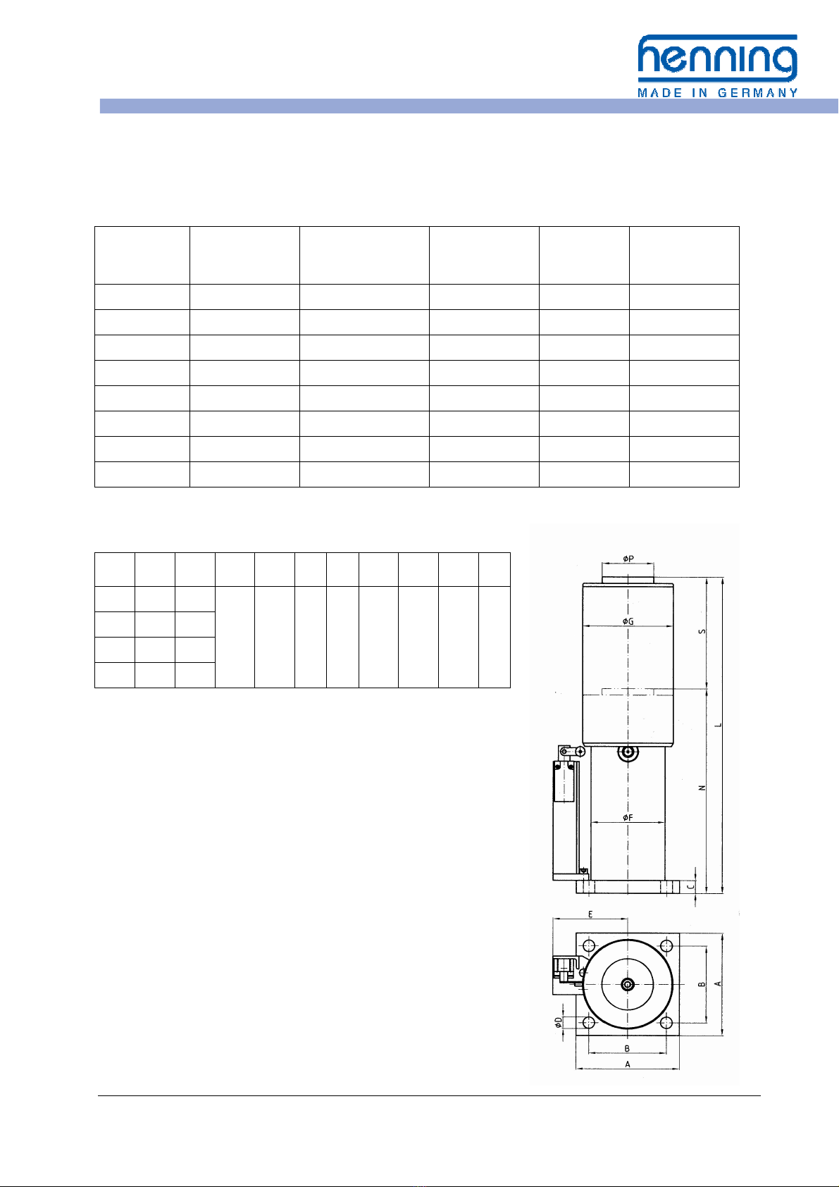
Dimensions Type LP 40 with protection tube:
S L N A B C D E F G P
80 305 225
160 120 20 18 112 115 140 80
120 385 265
175 495 320
275 715 440
All d mens ons n mm.
All data subject to mod f cat ons!
Henning
GmbH
&
Co.
KG
Loher Str. 4
58332 Schwelm
Germany
fon: +49 2336 92 98-0
fax: +49 2336 92 98-100
nfo@henn ng-gmbh.de
www.henn ng-gmbh.de
www.henn ng-cnc.de
Operat ng Instruct ons Elevator Buffers LP Page 11 Ed t on 3.3.1 EN of 03.04.2017
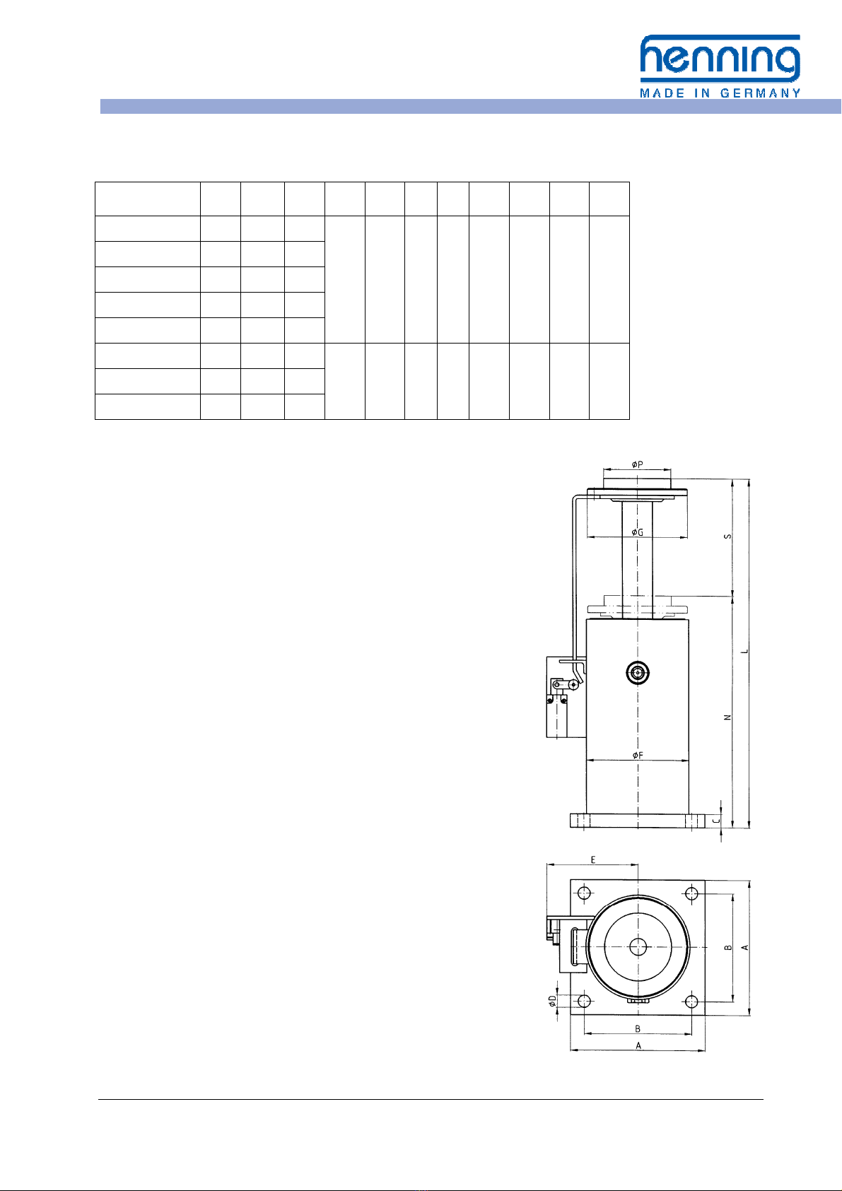
Dimensions Type LP 40 / 50 with linear slide:
S L N A B C D E F G P
LP 40 x
80 80 305 225
160 120 20 18 116 115 130 80
LP 40 x 120 120 385 265
LP 40 x 175 175 495 320
LP 40 x 275 275 715 440
LP 40 x 430 430 1065
635
LP 50 x 425 425 1065
640
200 160 20 18 135 155 150 100 LP 50 x 695 695 1665
970
LP 50 x 950 950 2235
1285
All d mens ons n mm.
All data subject to mod f cat ons!
Hydraulic oils and allowed ambient temperatures
during elevator operation:
a) buffer standard model:
Hydraul c o l DIN 51524-2 HLP respect ve ISO 6743/4 HM
v scos ty ISO VG 46 for amb ent temperatures from
-10 °C up to +50 °C
b) buffer with low temperature design (upon request):
Hydraul c o l DIN 51524-3 HVLP respect ve ISO 6743/4 HV
v scos ty ISO VG 22 for amb ent temperatures from
-20 °C up to +40 °C
c) Special designs with biodegradable or flame-retardant
hydraulic fluids (on request):
Var ous spec al flu ds are tested for the hydraul c buffer LP and
released for use.
Please note the spec al mark ng of the buffer and the add t onal
nserts for order documentat on n the nd v dual case!
Table of contents


