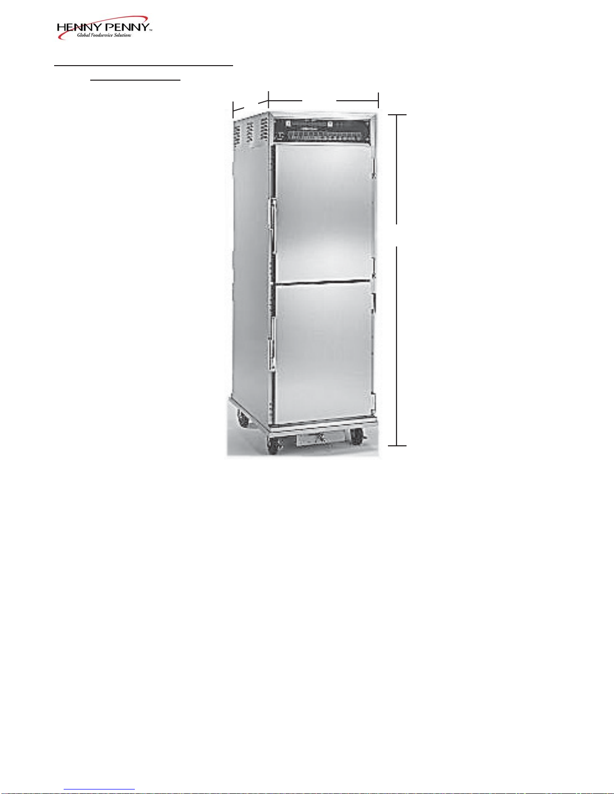
Henny Penny HHC-990 User manual

OPERATOR’S MANUAL
Henny Penny
Humidified Holding Cabinets
Model HHC-990
Model HHC-992
Model HHC-993
Model HHC-996
Model HHC-997
Model HHC-998

ModelHHC-990
LIMITED WARRANTY FOR HENNY PENNY APPLIANCES
Subject to the following conditions, Henny Penny Corporation makes the following limited warranties to the
original purchaser only for Henny Penny appliances and replacement parts:
NEW EQUIPMENT: Any part of a new appliance, except lamps and fuses, which proves to be defective
in material or workmanship within two (2) years from date of original installation, will be repaired or replaced
without charge F.O.B. factory, Eaton, Ohio, or F.O.B. authorized distributor. To validate this warranty, the
registration card for the appliance must be mailed to Henny Penny within ten (10) days after installation.
REPLACEMENT PARTS: Any appliance replacement part, except lamps and fuses, which proves to be
defectivein material or workmanship within ninety (90) days from date of original installationwill be repaired
or replaced without charge F.O.B. factory, Eaton, Ohio, or F.O.B. authorized distributor.
The warranty for new equipment and replacement parts covers only the repair or replacement of the defective
part and does not include any labor charges for the removal and installation of any parts, travel or other expenses
incidental to the repair or replacement of a part.
EXTENDED FRYPOT WARRANTY: Henny Penny will replace any frypot that fails due to manufacturing or
workmanship issues for a period of up to seven (7) years from date of manufacture. This warranty shall not cover
any frypot that fails due to any misuse or abuse, such as heating of the frypot without shortening.
0 TO 3 YEARS: During this time, any frypot that fails due to manufacturing or workmanship is-
sues will be replaced at no charge for parts, labor, or freight. Henny Penny will either install a new
frypot at no cost or provide a new or reconditioned replacement fryer at no cost.
3 TO 7 YEARS: During this time, any frypot that fails due to manufacturing or workmanship is-
sues will be replaced at no charge for the frypot only. Any freight charges and labor costs to install
the new frypot as well as the cost of any other parts replaced, such as insulation, thermal sensors,
high limits, fittings, and hardware, will be the responsibility of the owner.
Any claim must be presented to either Henny Penny or the distributor from whom the appliance was purchased.
No allowance will be granted for repairs made by anyone else without Henny Penny’s written consent. If damage
occurs during shipping, notify the sender at once so that a claim may be filed.
THE ABOVE LIMITED WARRANTY SETS FORTH THE SOLE REMEDY AGAINST HENNY PENNY
FOR ANY BREACH OF WARRANTY OR OTHER TERM. BUYER AGREES THAT NO OTHER REMEDY
(INCLUDING CLAIMS FOR ANY INCIDENTAL OR CONSEQUENTIAL DAMAGES) SHALL BE AVAIL-
ABLE.
The above limited warranty does not apply (a) to damage resulting from accident, alteration, misuse, or
abuse; (b) if the equipment’s serial number is removed or defaced; or (c) for lamps and fuses. THE
ABOVE LIMITED WARRANTY IS EXPRESSLY IN LIEU OFALLOTHER WARRANTIES, EXPRESS OR
IMPLIED,INCLUDING MERCHANTABILITYANDFITNESS,ANDALLOTHERWARRANTIESARE
EXCLUDED. HENNYPENNYNEITHERASSUMESNORAUTHORIZESANYPERSONTOASSUME
FORITANYOTHER OBLIGATIONOR LIABILITY.
FM05-007-D
Revised 10-13-04

ModelHHC-990
TABLE OF CONTENTS
Section Page
Section 1. INTRODUCTION
1-1. HumidifiedHoldingCabinet .................................................................................. 1-1
1-2. Features ................................................................................................................ 1-1
1-3. Proper Care .......................................................................................................... 1-1
1-4. Assistance............................................................................................................. 1-1
1-5. Safety.................................................................................................................... 1-2
Section 2. INSTALLATION
2-1. Introduction ........................................................................................................... 2-1
2-2. Unpacking ............................................................................................................. 2-1
2-3. Location ................................................................................................................ 2-2
2-4. ElectricalConnection ............................................................................................ 2-3
2-5. Cabinet Dimensions andWeights ......................................................................... 2-4
2-6. Probe Clip (Optional) ............................................................................................ 2-5
Section 3. OPERATION
3-1. Introduction ........................................................................................................... 3-1
3-2. Operating Controls ................................................................................................ 3-1
3-3. Start-Up ................................................................................................................ 3-4
3-4. Operation with Product......................................................................................... 3-5
3-5. Cleaning Procedures ............................................................................................. 3-6
Section 4. PROGRAMMING
4-1. TimerProgramming .............................................................................................. 4-1
4-2. Clock Set............................................................................................................... 4-1
4-3. SpecialProgramming ............................................................................................ 4-3
Section 5. TROUBLESHOOTING
5-1. TroubleshootingGuide........................................................................................... 5-1
5-2. Error Codes and Warnings.................................................................................... 5-2
GLOSSARY ......................................................................................................................... G-1
Distributors List - Domestic and International
i303

ModelHHC-990
1-1. HUMIDIFIED HOLDING The Henny Penny humidified holding cabinets are designed
CABINET to keep hot foods moist, while maintaining proper tempera-
ture. The units are electronically controlled for easy use and
for consistent operation.
1-2. FEATURES • Electronically controlled humidity and temperature
• Lift-off doors
• Stainless steel construction
• Easily maintained
• Lift-out tray racks
• Full perimeter magnetic door seals
• Easy access to electrical controls
• Food probe supplied to easily display food temperature
1-3. PROPER CARE Asinanyunitoffoodserviceequipment,theHennyPennyhumidi-
fiedholdingcabinetdoes require careandmaintenance.Require-
mentsforthemaintenanceandcleaningarecontainedinthismanual
andmustbecomea regularpart ofthe operation ofthe unitat all
times.
1-4. ASSISTANCE Should yourequireoutsideassistance, just callyourlocalindepen-
dentHennyPennydistributorin your area,orcallHennyPenny
Corp. 1-800-417-8405 toll free or 1-937-456-8405.
303 1-1
SECTION 1. INTRODUCTION

ModelHHC-990
1-5. SAFETY The Henny Penny Humidified Holding Cabinet has safety
features incorporated. However, to ensure a safe operation,
read and fully understand the proper installation, operation,
and maintenance procedures. The instructions in this manual
have been prepared to aid you in learning the proper proce-
dures. Where information is of particular importance or
safety related, the words WARNING, CAUTION, and
NOTICE are used. Their usage is described below.
SAFETYALERTSYMBOLis used withDANGER,
WARNING,orCAUTION which indicatesa personal injury
typehazard.
NOTICEisusedtohighlightespeciallyimportantinformation.
CAUTION used without the safety alert symbol indicates
a potentially hazardous situation which, if not avoided, may
result in property damage.
CAUTION used with the safety alert symbol indicates a
potentially hazardous situation which, if not avoided,
may result in minor or moderate injury.
WARNINGindicates apotentiallyhazardous situation
which,if not avoided,couldresultin death or serious
injury.
1-2 303

ModelHHC-990
2-1. INTRODUCTION
Installation of this unit should be performed only by a
qualified service technician.
Do not puncture the skin of the unit with drills or
screws, or component damage or electrical shock
could result.
2-2. UNPACKING The Henny Penny humidified holding cabinet has been
tested, inspected, and expertly packed to ensure arrival
at its destination in the best possible condition.
Note any shipping damage in the presence of the
delivery agent and signed prior to his or her departure.
To remove the Henny Penny cabinet from carton:
1. Carefully cut banding straps.
2. Lift carton off the unit.
3. Lift the unit off the cardboard padding and skid.
Full-size cabinets weigh approximately 300 lbs.
(136 kg). Care should be taken when lifting unit to
prevent personal injury.
303 2-1
SECTION 2. INSTALLATION

ModelHHC-990
2-2. UNPACKING(Continued) 4. Open doors and remove packing from behind racks and
the water pan in the bottom of the unit.
5. Peel off any protective covering from the exterior of the
cabinet.
6. The cabinet is now ready for location and use.
2-3. LOCATION Place the humidified holding cabinet in an area that allows
the doors to be opened without interference of loading and
unloading product. Also, keep the unit level for proper
operation.
No minimum clearances are required for the rear and
sides of the cabinet.
2-2 303

ModelHHC-990
2-4. ELECTRICAL CONNECTION
Toavoid electrical shock, the cabinet must be adequately
andsafely grounded (earthed)accordingtolocal electrical
codes,and this appliance mustbeequippedwith an exter-
nalcircuitbreakerwhichwilldisconnectallungrounded
(unearthed)conductors. Themainpowerswitchon this
appliancedoes not disconnect alllineconductors.
(FOR EQUIPMENT WITH CE MARK ONLY!)
To prevent electric shock hazard this appliance must be
bonded to other appliances or touchable metal surfaces
in close proximity to this appliance with an equipotential
bonding conductor. This appliance is equipped with an
equipotential lug for this purpose. The equipotential lug
is marked with the following symbol
If the electrical supply to the unit is a cord and plug, then the
electrical receptacle, for the plug, must be easily accessible.Refer
to the table below for the electrical ratings for the HHC-990
series cabinets.
Model Volts,60Hz Phase Amps Watts
HHC-990 120 1 24.0 2880
120 1 22.3 2680
208 1 13.8 2880
240 1 12.0 2876
240 1 11.2 2676
220-240-CE 1 11.6 2792
HHC-993/ 120 1 17.3 2080
HHC-992 208 1 10.0 2080
240 1 8.7 2076
220-240-CE 1 8.3 1992
HHC-996 120 1 27.3 3280
208 1 15.8 3280
240 1 13.7 3276
240 1 16.2 3876
220-240-CE 1 13.3 3192
HHC-997/ 120 1 17.3 2080
HHC-998 120 1 24.0 2880
120 1 22.3 2680
208 1 13.8 2880
240 1 8.7 2076
240 1 12.0 2876
220-240-CE 1 8.3 1992
220-240-CE 1 11.6 2792
1004 2-3

ModelHHC-990
2-5. CABINET DIMENSIONS
AND WEIGHTS
72-1/4” (1835 mm)
31-3/4” 24-3/4”
(806 mm) (628 mm)
HHC-990
Unit Height Width Depth ShippingWeight
HHC-993 38”(965mm) 24-3/4”(628 mm) 31-3/4” (806 mm) 220 lbs (100 kg)
HHC-990 72-1/4”(1835 mm) 24-3/4” (628 mm) 31-3/4”(806 mm) 367 lbs (167 kg)
HHC-992 76”(1930 mm) 24-3/4”(628 mm) 31-3/4”(806 mm) 493 lbs (224 kg)
HHC-998 38”(965mm) 27-3/4”(705 mm) 31-3/4” (806 mm) 269 lbs (122 kg)
HHC-996 72-1/4”(1835 mm) 27-3/4” (705 mm) 31-3/4”(806 mm) 400 lbs (181 kg)
HHC-997 76”(1930 mm) 27-3/4”(705 mm) 31-3/4”(806 mm) 523 lbs (237 kg)
2-4 303

ModelHHC-990
2-6. PROBECLIP (OPTIONAL) Theprobe clip is anaccessory, that maybe ordered as anoption,
tohold the food probe when not in use.
Removeoneof themodulescrews andmount the probeclip with
thatscrew. Seephoto atleft.
Thefood probeis accessedeasier ifthe clipis mountedon
theside of the unitthat the door opens. Seephoto below.
Probe Clip
Mount clip
here.
303 2-5

ModelHHC-990
3-1. INTRODUCTION This section provides explanations of all controls, along
with operating procedures and daily maintenance. Read the
Introduction, Installation and Operation Sections before
operating the unit.
3-2. OPERATING CONTROLS
Fig. Item
No No. Description Function
3-1 1 POWERSwitch Arockerswitch that sendselectrical current totheoperating
componentswhenturnedon
3-1 2 TemperatureLED Lightswhen thecontrolcallsfor heat, andtheunitshould start
heating; itgoesout once thetemperature inside thecabinet
reachestheprogrammedtemperaturesetting
PresstheTEMPERATURE Buttontoset thecabinet temperature
3-1 3 DigitalDisplay Showsthecabinettemperature,humidity settings,andtheselec-
tionsinthe ProgramMode; the temperatureof thecabinet
isshown by pressingthe INFObutton; if thetemperature
exceeds 300 °F (149°C), the display reads “E-5”, TOO HOT”.
3-1 4 HumidityLED Lightswhenthecontrolcallsfor humidity; it goesoutoncethe
humidityinsidethecabinet,reachestheprogrammedhumidity
setting
PresstheHUMIDITYbuttontoset the relativehumidityinside
thecabinet,and tochoose betweentheProofing andHolding
Modes,whenthe unitisturned on
3-1 5 Pressto viewthe foodprobe temperature,cabinet temperature
andhumidity,dateand time;ifpressed intheProgram Mode,
showsprevious settings; pressing this along with accesses
theInformationModewhichhashistoricinformationonthe
cabinet’sperformance
3-1 6 & 7 Usedtoadjustthevalue ofthecurrentlydisplayedsetting in
theProgram Mode
3-1 303
SECTION 3. OPERATION

ModelHHC-990
3-2. OPERATING CONTROLS
(Continued)
3-1 8 Used to access the Program Modes; once in the Program Mode,
itisused toadvance to thenext parameter;pressingthis along
with accesses the Information Mode
whichhashistoricinformationonthecabinet’sperformance
3-1 9 Food Probe Afterpluggingthe foodprobe intothe receptacle, themeat probe
Receptacle canthen beinserted intothe productand theproduct temperature
isdisplayed
3-1 10 CountDown Onceatray offood is placed in thecabinet, theappropriate timer
Timers is pressed,and the timeremainingshows in thedisplayabove the
timernumber; oncethe timercountsdown tozero, the display
flashes“0:00”, and the control beeps; the HHC-990 and996
have15 timers, and theHHC-993 and 998 have5 timers
303 3-2

ModelHHC-990
1 2 3 4 5 6 7 8
9
10
Figure 3-1
Control Decal
3-3 303
3-2. OPERATING CONTROLS
(Continued)

ModelHHC-990
3-3. START-UP
Before using the humidified holding cabinet, thoroughly
clean the unit as described in the Cleaning Procedures
Section of this manual.
1. Plug unit into electrical receptacle, or turn on wall circuit
breaker. With the POWER switch turned to OFF the
display shows “POWER OFF.”
With the POWER Switch off, the display may show
“PURGING”. This means the humidity has reached
95% inside the unit and the fan runs to help drop the
humidity. Once the humidity reaches 92%, “POWER
OFF” again shows in the display.
Even though POWER switch is OFF it does not dis-
connect all electrical supplies to the controls.
Unplug power cord, or turn off wall circuit breaker
before servicing any electrical components, or
electrical shock could result.
2. Turn the POWER switch to ON, and the display
shows “PUSH TO PROOF”.
3. If the unit is to be used as a proofer, (80-140o F)
(27-60o C), press the HUMIDITY button within 10
seconds, while thedisplay still shows “PUSH
TO PROOF”. If not, allow unit to heat normally,
(140o-210o F) (60o-99o C).
4. Open door of unit and pour up to 3 gallons of water
into bottom water pan, (minimum 1 gallon) up to the slot
on the concentration ring. See figure 3-2.
Do not overfill the water pan, or water could over
flow and spill onto the floor, and personal injury
could result.
303 3-4
Figure 3-2
Slot

ModelHHC-990
3-3. START-UP(Continued) 5. Press theTEMPERATURE button to set the desired
cabinet temperature. While the LED is flashing, press
the UP and DOWN buttons until the desired tempera-
ture shows in the display.
6. Press the HUMIDITY button to set the desired cabinet
humidity (OFF to 90%). While the LED is flashing,
press the UP and DOWN buttons until the desired
temperature shows in the display.
7. Allow the unit to preheat for about 1 hour prior to
placing product in the cabinet. This allows the interior
conditions to stabilize.
3-4. OPERATION WITH 1. The LEDs above the TEMPERATURE and HUMIDITY
PRODUCT buttons go out when the desired temperature and
humidity are reached inside the cabinet. Place hot
product on pan and slide pan onto the racks of the
cabinet.
The minimum holding temperature for potentially
hazardous product is 150o F (66o C). Use the food
probe to accurately display food temperature. Also,
the cabinet product load capacity for the full size
units is 375 lbs. (170 kg.), and 125 lb. (57 kg.) for
the half-sized units. View the temperature at any
time by pressing .
2. Press the appropriate timer button (1-15), and the
time, (hours:minutes), starts counting down in display.
3. At the end of the timing period, the control beeps, and
“0:00” flashes in display.
A float switch in the water pan senses when the
water level is low and the display shows “WATER
LEVEL LOW”. Add more water to the water pan.
4. Open the doors only as necessary to load and unload
product. This helps to keep the interior conditions
constant and saves energy.
3-5 303

ModelHHC-990
3-5. CLEANING Daily:
PROCEDURES 1. Turn all controls off and disconnect electrical supply.
Toavoid burns, allow the unittocoolbeforecleaning.
2. Open doors and remove all trays and racks from unit,
and take them to a sink to thoroughly clean.Figure 3-3.
Figure 3-3 3. Wipe interior and exterior of cabinet with damp cloth,
soap and water.
Do not use steel wool, other abrasive cleaners or
cleaners/sanitizers containing chlorine, bromine, iodine
or ammonia chemicals, as these will deteriorate the
stainless steel, and glass material, and shorten the life
of the unit.
Do not use a water jet (pressure sprayer) to
clean the unit, or component failure could result.
4. Wipe the control panel with a damp cloth. Do not
splash water around controls.
5. Reinstall racks, and leave a door partially open over
night to allow interior cabinet to thoroughly dry.
303 3-6

ModelHHC-990
3-5. CLEANING Weekly:
PROCEDURES (Continued) 1. Remove pans and racks from cabinet.
2. Open drain valve and empty water pan into a shallow
pan or floor drain. See Figure 3-4.
Hot water! Do not place your hand under the
drain while draining the unit. Failure to follow this
Figure 3-4 warning could result in severe burns and injury.
3. Remove concentration ring assembly from water pan.
See Figure 3-5.
Concentration ring could be hot! Allow to cool
before removing, or burns could result.
Figure 3-5 4. Wash the concentration ring in a dishwasher or sink.
5. Liberally spray the water pan with a concentrated
deliming agent and let stand for 10 minutes.
To avoid damage to the unit, delime the unit weekly.
6. Scrub the pan with a brush and flush with water.
7. Return concentration ring assembly to the water pan.
8. Reinstall the racks and fill the water pan with water to
the maximum water fill line.
9. Unit is now ready for use.
Monthly:
1. Remove the 2 screws securing the vented panel on the
rear of the module and remove the panel, and clean
vents.
2. Using a cloth or sponge, clean the trough once a
month.
Figure 3-4
3-7 303

ModelHHC-990
Thissectionexplainsthefollowingprogrammingfunctions.
• Timerprogramming
• Clock-set
• Specialprogramming
4-1. TIMER PROGRAMMING Toenter theProgram Mode:
1. Press andhold for2 seconds, and “PROG TMRS”
showsindisplay.
2. After 5seconds, “ENTER CODE”shows indisplay.
3. Press , and “PUSH TIMER BUTTON
“TOSELECTFOR PROGRAMMING,” followedby
“USE UPAND DOWNTO CHANGE SELECTED
TIMERS,” scrollsthroughthedisplay.
4. Pressthe desiredtimer button (1-15). (More thanone can
beprogrammedat onetime).
5. Press tochangetheselected timer settings.
6. Once timers are set, press and hold the , and new timer
settingsbecomeactiveand normal operationisresumed.
4-2. CLOCK SET 1. Press andhold for5 seconds,and LEVEL 2, then
(Time-of-day,date,and
day of the week) “CLOCKSET”shows indisplay.
2. After 5seconds, “ENTER CODE”shows indisplay.
3. Press .
4. “CS-1, SET, HOUR”,and the time of day(with thehour
flashing)showsinthedisplay.
5. Press the tochange the hours.
303 4-1
SECTION 4. PROGRAMMING

ModelHHC-990
4-2. CLOCK SET 6. Press and“CS-2, SET, MINUTE” showsin the
(Continued) display,withtheminutesflashing.
7. Press to change the minutes.
8. Press and“CS-3, SET, MONTH”shows in the
display,alongwiththedate(monthflashing).
9. Press to change the month.
10. Press and“CS-4,SET,DATE”shows inthe display,
withthedateflashing.
11. Press to change the date.
12. Press and “CS-5, SET,YEAR” shows in the display,
withtheyearflashing.
13. Press to change the year.
14. Pressandhold toexitprogramming.
4-2 303

ModelHHC-990
4-3. SPECIAL PROGRAMMING Thismodeallowsyoutoprogramthefollowing:
SP-1 • Fahrenheit/celsius
SP-2 • Lock/unlock
SP-3 • Airtemperaturesetpoint
SP-4 • Humiditysetpoint
SP-5 • Proofairtemperature
SP-6 • Proofhumiditysetpoint
SP-7 • Outof water tripp point
SP-8 • Cleanwaterpan setpoint
SP-9 • Systemintialization
SP-10 • Audiovolume
SP-11 • Audiotone
SP-12 • Audioeffects
SP-13 • Languageoptions
SP-1 Fahrenheit/Celsius 1. Press andhold the until“LEVEL2”,then“CLOCKSET”
showsinthedisplay.
2. Press again, then“SPPROG”showsin display.
3. After 5seconds, “ENTER CODE”shows indisplay.
4. Press and “SP-1,TEMP, UNITS” and
“oF”or“oC”shows inthe display.
5. Press the tochange temperatureunits.
SP-2 Lock/Unlock 6. Press and “SP-2, LOCK/UNLOCK PROGRAMMING’
showsindisplay,along witheither“LOCK” or “UNLOCK”.
7. Press tochange lock theprogramming orunlock the
programming.
SP-3 AirTemperatureSetpoint 8. Press and “SP-3,AIRTEMPSETPOINT,” and the
presetcabinettemperatureshows indisplay.
9. Press tochange the air temperature setpoint,
140o F(60o C)minimum, 210oF (99o C)maximum.
303 4-3
Other manuals for HHC-990
1
This manual suits for next models
5
Table of contents
Other Henny Penny Food Saver manuals
Popular Food Saver manuals by other brands

Gastroback
Gastroback DESIGN PRO operating instructions

All American
All American 1502 Operator's manual

Xytronic
Xytronic LF-90 user manual

OBH Nordica
OBH Nordica 7952 instruction manual

Traditional Tool Repair
Traditional Tool Repair A461.0002 Operation manual and spare parts list

SealerSales
SealerSales W Series quick start guide