Palmgren 82064 User manual

ooppeerraattiinnggmmaannuuaall&&ppaarrttsslliisstt8822006644
66″″VVaarriiaabblleessppeeeedd
BBEENNCCHHGGRRIINNDDEERR
Read carefully and follow all safety rules and operating instructions before
first use of this product.
17994.19-0402

DDEESSCCRRIIPPTTIIOONN
This Palmgren Bench Grinder is equipped with a totally enclosed
ball bearing motor. Armature assembly is dynamically balanced for
smooth operation. Motor housing is compact so long pieces of
work can press against both wheels without touching the motor
frame. Grinder operates at 3450 rpm for grinding and also at 2000-
3300 rpm for sharpening. Removable wheel guards allow for easy
changing of wheels.Two-way tool rests are adjustable for wheel
wear and angle grinding. Grinder comes complete with spark
guards, safety eyeshields and dust collection hose.
UUNNPPAACCKKIINNGG
Check for shipping damage. If damage has occurred, a claim must
be filed with the carrier immediately. Check for completeness.
Immediately report missing parts to dealer.
SPECIFICATIONS
Horsepower . . . . . . . . . . . . . . . . . . . . . . . . . . . . . . . . . . . . . . . . . . . . . . . . . .1/3
Voltage . . . . . . . . . . . . . . . . . . . . . . . . . . . . . . . . . . . . . . . . . . . . . . . . . . . .120
Amperes . . . . . . . . . . . . . . . . . . . . . . . . . . . . . . . . . . . . . . . . . . . . . . . . . . . 3.5
Hertz . . . . . . . . . . . . . . . . . . . . . . . . . . . . . . . . . . . . . . . . . . . . . . . . . . . . . . .60
Phase . . . . . . . . . . . . . . . . . . . . . . . . . . . . . . . . . . . . . . . . . . . . . . . . . . .Single
RPM . . . . . . . . . . . . . . . . . . . . . . . . . . . . . . . . . . . . . . . . . . .2000-3300, 3450
Rotation (viewed from left side) . . . . . . . . . . . . . . . . . . . . . . . .Clockwise
Wheel diameter . . . . . . . . . . . . . . . . . . . . . . . . . . . . . . . . . . . . . . . . . . . . . .6”
Wheel bore . . . . . . . . . . . . . . . . . . . . . . . . . . . . . . . . . . . . . . . . . . . . . . . . .1/2”
SSAAFFEETTYYRRUULLEESS
WARNING: For your own safety, read operating instructions man-
ual before operating tool.
BE PREPARED FOR JOB
•Wear proper apparel. Do not wear loose clothing, gloves, neck-
ties, rings, bracelets or other jewelry which may get caught in
moving parts of machine.
•Wear protective hair covering to contain long hair.
•Wear safety shoes with non-slip soles.
•Wear safety glasses complying with United States ANSI Z87.1.
Everyday glasses have only impact resistant lenses.They are
NOT safety glasses.
•Wear face mask or dust mask if operation is dusty.
•Be alert and think clearly.Never operate power tools when
tired, intoxicated or when taking medications that cause
drowsiness.
PREPARE WORK AREA FOR JOB
•Keep work area clean. Cluttered work areas and work benches
invite accidents.
•Do not use power tools in dangerous environments. Do not use
power tools in damp or wet locations. Do not expose power
tools to rain.
•Work area should be properly lighted.
•Proper electrical plug should be plugged directly into properly
grounded, three-prong receptacle.
•Extension cords should have a grounding prong and the three
wires of the extension cord should be of the correct gauge.
•Keep visitors at a safe distance from work area.
•Keep children out of the workplace. Make workshop childproof.
Use padlocks, master switches or remove switch keys to pre-
vent any unintentional use of power tools.
TOOL SHOULD BE MAINTAINED
•Always unplug tool prior to inspection.
•Consult manual for specific maintaining and adjusting proce-
dures.
•Keep tool clean for safest operation.
•Remove adjusting tools. Form habit of checking to see that
adjusting tools are removed before turning machine on.
•Keep all parts in working order. Check to determine that the
guard or other parts will operate properly and perform their
intended function.
•Check for damaged parts. Check for alignment of moving parts,
binding of moving parts, breakage of parts, mounting and any
other condition that may affect a tool’s operation.
•A guard or other part that is damaged should be properly
repaired or replaced. Do not perform makeshift repairs. (Use
the parts list to order replacement parts.)
KNOW HOW TO USE TOOL
•Use right tool for job. Do not force tool or attachment to do a
job for which it was not designed.
•Disconnect tool from power when changing accessories such
as grinding wheels, buffing wheels and the like.
•Avoid accidental start-up. Make sure that the switch is in the off
position before plugging in.
•Do not force tool. It will work most efficiently at the rate for
which it was designed.
•Keep hands away from moving parts and grinding surfaces.
•Never leave a tool running unattended.Turn the power off and
do not leave tool until it comes to a complete stop.
•Do not overreach. Keep proper footing and balance.
•Never stand on tool. Serious injury could occur if tool is tipped
over.
•Know your tool. Learn the tool’s operation, application and spe-
cific limitations.
•Use recommended accessories. Understand and obey all safety
instructions supplied with accessories.The use of improper
accessories may cause risk of injury to persons.
•Do not over tighten wheel nut. Replace cracked wheel immedi-
ately. Use only flanges supplied with the grinder.
•Adjust distance between wheel and tool rest to maintain 1/16”or
less gap.
•Handle the workpiece correctly. Whenever possible, use tool
rest to support workpiece during grinding operation.Turn tool
off if it jams.
•Always use guards and eyeshields.
•Clean grinding dust from beneath tool frequently.
2
Palmgren Operating Manual & Parts List 82064

3
AASSSSEEMMBBLLYY
Parts to be fastened to the unit should be located and accounted
for (See List and Figure 1).
IMPORTANT: Do not attempt assembly if parts are missing. Use
this manual to order replacement parts.
A5/16-18 x 11/2”Carriage bolt, 2 each
B Tool rest bracket, 2 each
C*
3/8” Flat washer, 4 each
D*
3/8”-16 Hex nut, 4 each
E Tool rest, 2 each
F5/16” Flat washer, 2 each
G5/16”-18 Hex nut, 2 each
H*
3/8-16 x 1¼” Hex bolt, 4 each
I Knob, 2 each
J Spark guard, 2 each
K Eyeshield, 2 each
L Lower eyeshield bracket, 2 each
M Upper eyeshield bracket, 2 each (left and right)
N #10-24 x 3/8” Pan head screw, 4 each
O 6-1.0 x 12mm” Flange screw, 2 each
P 6mm Flat washer, 2 each
Q Spacer, 2 each
R Dust collector hose (not shown)
NOTE: Parts marked with an asterisk (*) are mounted to the
grinder at the factory.
TOOL REST ASSEMBLY
•Slide 5/16-18”carriage bolt (A) into square hole in tool rest bracket
(B). Slide spacer (Q) onto carriage bolt. Slide carriage bolt with
bracket into hole on inside of tool rest (E) as shown in Figure 1.
Slide 5/16”flat washer (F) and 5/16”-18 hex nut (G) onto carriage bolt.
Tighten nut finger tight.
•Remove 3/8”hex nut (D) and flat washer (C) from 3/8-16 x 1¼”hex
bolt (H) mounted to bottom front of left wheel guard.
•Slide slot in tool rest bracket over 3/8”bolt. Replace flat washer
and hex nut. Position tool rest so that distance between tool
rest and grinding wheel is less than 1/16”. Secure all nuts and bolts.
•Mount right tool rest in a similar manner.
EYESHIELD ASSEMBLY
•Remove 3/8”hex nut (D) and 3/8” flat washer (C) from 3/8-16 x 1¼”
hex bolt (H) mounted to top front of left wheel guard.
•Slide slot in spark guard (J) over hex bolt and replace washer
and hex nut.
•Remove pan head screws (N) from eyeshield assembly. Mount
left upper eyeshield bracket (M) to eyeshield using pan head
screws and lower eyeshield bracket.
NOTE: Left upper eyeshield bracket is stamped“L”for identification.
•Slide 6-1.0 x 12mm flange screw (O) and 6mm flat washer (P)
through left upper eyeshield bracket (M) and through hole at
top of left spark guard (J) and secure with knob (I).
•Locate eyeshield in desired position for protecting operator
and secure all nuts and bolts.
•Mount right eyeshield assembly in a similar manner.
DUST COLLECTOR HOSE
•A dust collector hose has been provided with grinder. Slide
hoses onto sides of T-connector and flanges. Mount the hose
by sliding the flanges at each end over the exhaust ports on
the left and right wheel guards. Attach 2½” shop vacuum hose
to collector hose. Be sure hose is mounted securely.
DANGER: Be sure to empty shop vacuum of all flammable materi-
al (flammable liquids and vapors, paper, wood, plastic, etc.) before
connecting vacuum to grinder. Hot sparks from grinder may ignite
flammable materials in shop vacuum.
IINNSSTTAALLLLAATTIIOONN
MOUNT GRINDER
•Mount grinder to a solid horizontal surface (hardware not pro-
vided). If mounted to metal pedestal, align mounting holes
with corresponding holes in pedestal. Insert a 1/4-20 x 1¼” hex
head bolt with flat washer through base of grinder. From bot-
tom of pedestal, place a 1/4” flat washer and 1/4”-20 hex nut onto
the bolt.Tighten only until space between grinder base and
pedestal is 1/8”. Using second nut on each bolt, jam tighten
against the first to prevent loosening by vibration.
•To mount grinder to wooden bench top, use 1/4x 1¼” wood
screws with flat washers beneath heads.Tighten screws until
space between grinder base and bench top is 1/8”.
GROUNDING INSTRUCTIONS
WARNING: Improper connection of equipment grounding con-
ductor can result in the risk of electrical shock. Equipment should
be grounded while in use to protect operator from electrical shock.
•Check with a qualified electrician if grounding instructions are
not understood or if in doubt as to whether the tool is properly
grounded.
•This grinder is equipped with an approved 3-conductor cord
rated at 300V and a 3-prong, grounding type plug (See Figure
2) for your protection against shock hazards.
Palmgren Operating Manual & Parts List 82064
Figure 1 – Left Tool Rest and Eyeshield Assembly
J
G
MN
OP
D
C
C
B
D
E
F
A
L
I
K
H
Figure 2 – 3-Prong Receptacle
Properly Grounded Outlet
Grounding Prong
3-Prong Plug
Q

4
INSTALLATION (CONTINUED)
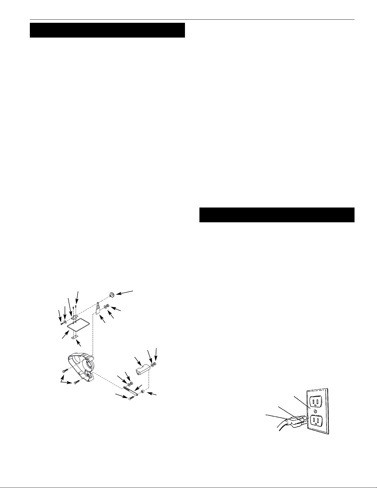
•Grounding plug should be plugged directly into a properly
installed and grounded 3-prong grounding-type receptacle
(See Figure 2).
•Do not remove or alter grounding prong in any manner. In the
event of a malfunction or breakdown, grounding provides a
path of least resistance for electrical shock.
WARNING: Do not permit fingers to touch the terminals of plug
when installing or removing from outlet.
•Plug must be plugged into matching outlet that is properly
installed and grounded in accordance with all local codes and
ordinances. Do not modify plug provided.If it will not fit in out-
let, have proper outlet installed by a qualified electrician.
•Inspect tool cords periodically, and, if damaged, have repaired
by an authorized service facility.
•Green (or green and yellow) conductor in cord is the grounding
wire. If repair or replacement of the electric cord or plug is nec-
essary, do not connect the green (or green and yellow) wire to
a live terminal.
•Where a 2-prong wall receptacle is encountered, it must be
replaced with a properly grounded 3-prong receptacle installed
in accordance with National Electric Code and local codes and
ordinances.
WARNING: This work should be performed by a qualified
electrician.
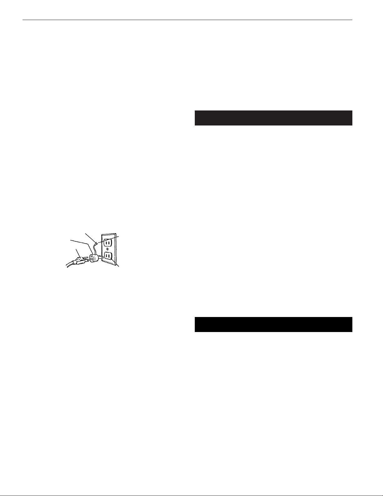
•A temporary 3-prong to 2-prong grounding adapter (See
Figure 3) is available for connecting plugs to a two pole outlet
if it is properly grounded.
•Do not use a 3-prong to 2-prong grounding adapter unless
permitted by local and national codes and ordinances.
(A 3-prong to 2-prong grounding adapter is not permitted in
Canada.) Where permitted, the rigid green tab or terminal on
the side of the adapter must be securely connected to a per-
manent electrical ground such as a properly grounded water
pipe, a properly grounded outlet box or a properly grounded
wire system.
•Many cover plate screws, water pipes and outlet boxes are not
properly grounded.To ensure proper ground, grounding means
must be tested by a qualified electrician.
EXTENSION CORDS
•The use of any extension cord will cause some drop in voltage
and loss of power.
•Wires of the extension cord must be of sufficient size to carry
the current and maintain adequate voltage.
•Running the unit on voltages which are not within ±10% of the
specified voltage may cause overheating and motor burn-out.
•Use the table to determine the minimum wire size (A.W.G.)
extension cord.
•Use only 3-wire extension cords having 3-prong grounding
type plugs and 3-pole receptacles which accept the tool plug.
•If the extension cord is worn, cut or damaged in any way,
replace it immediately.
EXTENSION CORD LENGTH
Wire Size . . . . . . . . . . . . . . . . . . . . . . . . . . . . . . . . . . . . . . . . . . . . . . . .A.W.G.
Up to 25 ft. . . . . . . . . . . . . . . . . . . . . . . . . . . . . . . . . . . . . . . . . . . . . . . . . . .16
NOTE: Using extension cords over 25 ft. long is not recommended.
ELECTRICAL CONNECTIONS
WARNING: All electrical connections must be performed by a
qualified electrician. Make sure tool is off and disconnected from
power source while motor is mounted, connected, reconnected or
anytime wiring is inspected.
•Motor is assembled with approved, 3-conductor cord to be
used at 120 volts. Motor is prewired at the factory for 120 volts.
OOPPEERRAATTIIOONN
Refer to Figure 4.
WARNING: Always wear safety glasses complying with United
States ANSI Z87.1 (shown on package) before commencing power
tool operation.
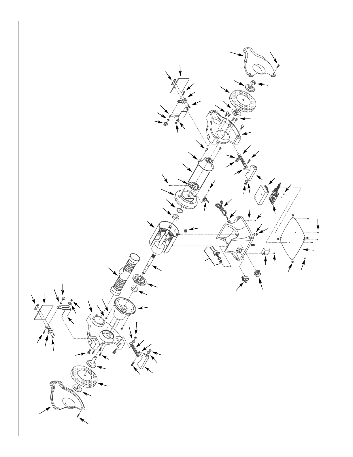
•To turn grinder “ON”, flick switch upward (Ref. No. 39). NOTE:
switch has a key which can be removed to prevent unautho-
rized use.
•To operate grinder at full speed (3450 RPM), turn knob (Ref.No.
59) completely counterclockwise.
•To operate grinder at a slower speed turn knob clockwise.The
speed is infinitely variable from 2000 to 3300 rpm.
•Keep a steady, moderate pressure on the work and keep it
moving at an even pace for smooth grinding.
•Pressing too hard overheats the motor and prematurely wears
down the grinding wheels.
•Note the original bevel angle on the item to be sharpened and
try to maintain that angle. Sharpening a cutting edge requires
removing burrs from edge.
•Deburring edge is done best by using the grinder to pull burr
from edge across the bevel angle.
•The grinding wheel should rotate into object being sharpened.
•Use slower wheel speed when sharpening tempered tools.
Overheating will destroy the temper.
•When grinding at high speed, dip work into a coolant regularly
to prevent overheating. Overheating can weaken metals.
MMAAIINNTTEENNAANNCCEE
•As wheels wear, tool rests should be positioned closer to the
face of the wheels.
•The gap between the wheel and the tool rest should not be
greater than 1/16”.When the wheels are worn to the extent that
the 1/16” maximum gap cannot be maintained, the wheels
should be replaced.
•Replacement wheels should have a minimum rated speed of at
least 3600 RPM.
•Maximum wheel diameter is 6”.
•To loosen nuts holding the wheels, disconnect power and push
a wood wedge between the tool rest and the wheel to keep
the shaft from turning.The threads on the right side of the
grinder (facing unit) are right hand; threads on the left side are
left hand.Tighten nuts securely before operating the grinder.
•For grinding efficiency, wheels should be dressed periodically,
especially if they become clogged from grinding soft metals.
Figure 3 – 2-Prong Receptacle
Grounding Lug
Adapter
3-Prong Plug
2-Prong Receptacle
Make sure this is
Connected to a known
Grounded Receptacle
Palmgren Operating Manual & Parts List 82064

5
SYMPTOM
Grinder won’t start
Excessive vibration
Grinder overheating
Fuses are being blown or
circuit breakers are being tripped
Grinder will not operate in variable speed
mode
POSSIBLE CAUSE(S)
1. Blown line fuse or tripped circuit breaker
2. Low line voltage
3. Material wedged between wheel
and guard
4. Defective switch
5. Defective, blown capacitor
6. Defective circuit board
1. Improper mounting of grinder or
accessories
2. Grinding wheel out of balance
3. Improper wheel mounting
1. Excess pressure required to grind material
2. Grinding on side of wheel
3. Motor not turning freely (without power)
1. Overloading due to binding
2. Defective plug
3. Defective cord
4. Defective switch
5. Faulty internal wiring
1. Defective variable speed switch
2. Defective sensor
3. Defective circuit board
CORRECTIVE ACTION
1. If fuse is blown, replace with fuse of
proper size.If breaker tripped, reset it
2. Check power supply for voltage and
correct as needed
3. Turn grinder off and remove material
4. Replace switch
5. Replace capacitor
6. Replace circuit board
1. Remount
2. Dress wheels or replace wheels
3. Remount wheels, but rotate one wheel
90º with respect to its previous position.
Other wheel should remain in its original
position
1. Dress wheel or replace wheel with one of
proper grit
2. Grind only on face of wheel
3. Clean around wheels and shaft and/or
replace bearings
1. Clean around wheels and shaft and/or
replace bearings
2. Replace plug
3. Replace cord
4. Replace switch
5. Contact your Palmgren distributor
1. Replace switch
2. Replace sensor
3. Replace circuit board
TTRROOUUBBLLEESSHHOOOOTTIINNGG
Palmgren Operating Manual & Parts List 82064

6
Palmgren Operating Manual & Parts List 82064
1
2
3
4
4
7
6
30
20
21
16
11
15
15
9
10
16
13
8
6
5
3
61
13
12
1
20
60
52
58
55
45
50
56
59
57
29
48
45
46
26
25
24
52
53
54
51
39
49
17
19
17
12
47
48
19
30
31 32
35
34
23
27
62
28
18
47
10
44
43
13
12
14
22
12
41
36
33
23
42
13
27
62
24
14
26
26
18
37
40
Figure 4 - Replacement Parts Illustration for 6” Bench Grinder

7
Palmgren Operating Manual & Parts List 82064
∆Not Shown.
* Standard hardware item available locally.
Ref. Part
No. Description Number Qty.
1 #10-24 x 7/8” Pan Head Screw * 10
2 Dust Collector Hose 08070.01 1
3 Spark Guard (Set of 2) 16841.00 1
4 Wheel Guard Cover 16615.09 2
5 Flange Nut 17289.00 1
6 Wheel Flange 00065.01 2
7 Inner Wheel Flange 17316.00 1
8 Grinding Wheel (36 coarse grit) 02034.00 1
9 Grinding Wheel (60 med. grit) 02033.00 1
10 3/8-16 x 1¼”Hex Head Bolt * 4
11 5-0.8mm Hex Nut * 2
12 3/8” Flat Washer * 4
13 3/8”-16 Hex Nut * 4
14 5/16-18 x 11/2”Carriage Bolt * 2
15 Spacer 04028.00 2
16 Tool Rest 04030.00 2
17 5/16” Flat Washer * 2
18 5/16”-18 Hex Nut * 2
19 Bracket 04029.00 2
20 #10-24 x 3/8” Pan Head Screw * 4
21 Upper Eyeshield Bracket (left) 00284.01 1
22 Upper Eyeshield Bracket (right) 00282.01 1
23 Eyeshield 00281.00 2
24 Lower Eyeshield Bracket 00280.00 2
25 Wheel Guard (left) 16616.09 1
26 #10-24 x 1/4” Flange Screw 03210.00 6
27 1/4-20 x 3/8”Flange Screw 16670.00 6
28 5- 0.8 x 190mm Pan Head Screw 17995.00 2
29 Endshield 16617.09 1
30 Bearing 6202ZZ 01540.00 2
31 Motor Fan 01608.00 1
32 Armature 17996.00 1
33 Stator With Housing 16619.09 1
Ref. Part
No. Description Number Qty.
34 Grommet 01066.00 1
35 Line Cord 00067.00 1
36 Strain Relief 04055.00 1
37 Base Cover 18488.00 1
38 Base 18489.09 1
39 Switch With Key 08066.00 1
40 Base Bumper 04051.00 4
41 1/4” Lock Washer * 2
42 1/4”-20 Hex Nut * 2
43 Wheel Guard (right) 16845.09 1
44 Capacitor 16908.00 1
45 5mm Serrated Washer * 3
46 Variable Switch 17997.00 1
47 6mm Flat Washer * 2
48 Knob 16714.00 2
49 Wavy Washer 08283.00 1
50 Knob 17998.00 1
51 Circuit Board 17999.00 1
52 4-1.4 x 8mm Thread Forming Screw 09652.00 4
53 Sensor 18000.00 1
54 3-0.5 x 6mm Pan Head Screw 05990.00 2
55 Endshield 18001.09 1
56 Endshield Cap 18002.09 1
57 Plate 18003.00 1
58 4-0.7 x 6mm Dog Point Set Screw 09229.00 1
59 1/2”-12 Hex Nut 00548.00 1
60 Cover 18005.00 1
61 #10-24 x 3/8” Flange Screw 03207.00 2
62 6-1.0 x 12mm Flange Screw 16668.00 2
∆Operators Manual 17994.19 1
Recommended Accessories
∆Cast Iron Tool Stand 70101 1
RREEPPLLAACCEEMMEENNTTPPAARRTTSSLLIISSTTFFOORR66”BBEENNCCHHGGRRIINNDDEERR

WWAARRRRAANNTTYY
FULL TWO YEAR WARRANTY ON PALMGREN BENCH GRINDER
If within two full years from the date of purchase, this Palmgren Bench Grinder fails due to a defect in material or
workmanship, Palmgren will repair it free of charge.
To order parts for a non-warranty repair, please contact your preferred Palmgren distributor.To obtain the names of Palmgren
distributors or to arrange warranty return, please call Palmgren Steel Products directly at (800) 621-6145.
This warranty gives you specific legal rights and you may have other rights which vary from state to state.
Palmgren Steel Products, Inc., 914 N. Kilbourn Avenue, Chicago, IL 60651-3426
Palmgren Operating Manual & Parts List 82064
Table of contents
Other Palmgren Grinder manuals

Palmgren
Palmgren 9682096A User manual

Palmgren
Palmgren 82066 User manual

Palmgren
Palmgren 82401 User manual

Palmgren
Palmgren 82064A User manual

Palmgren
Palmgren 9682096 User manual

Palmgren
Palmgren 82061C User manual

Palmgren
Palmgren 82088 User manual

Palmgren
Palmgren 82061B User manual

Palmgren
Palmgren 82121 User manual

Palmgren
Palmgren 82102A User manual
Popular Grinder manuals by other brands

EINHELL
EINHELL bavaria BWS 115/850-2 operating instructions

Milwaukee
Milwaukee AG 16-125 XC Dissambly instruction

Fein
Fein GRIT GHB 15-50 instruction manual

Vist
Vist VORHUT VAG-120S user manual

Bosch
Bosch Professional GWS 18-125 L Original instructions

Parkside Performance
Parkside Performance HG02735 manual