HENRY A1584 User manual

INSTALLATION, OPERATION AND MAINTENANCE MANUAL
A1584 5 AMP POWER SUPPLY (TERMINAL VERSION)
Contents Page
1. Introduction 1
2. Warnings 2
3. General Description 3
4. Specification 5
5. Terminations List 5
6. Adjustments and Indications 6
7. Installation Procedure 7
8. Commissioning 8
1. Introduction
Thank you for purchasing this 5A Power Supply Unit. This power supply is designed
to the requirements of EN54-4. This power supply will provide the user with many
years of reliable service.
NOTE: It is important to read this manual before commencing installation.
Document Ref: O&M15845T.DOC/Rev 0 16.11.99 Page 1 of 8 Originator KP Checked AP Approved JBJ

2. WARNING
IMPORTANT NOTE ON BATTERIES:
DANGER: Batteries are electrically live at all times, take great care never to short circuit the battery
terminals.
WARNING: Batteries are often heavy, take great care when lifting and transporting batteries. For
weights above 24kg, lifting aids should be used.
WARNING: Do not attempt to remove the battery lid or tamper with the battery internal workings.
Electrolyte is a highly corrosive substance and presents significant danger to yourself and to
anything else it touches. In case of accidental skin or eye contact, flush the affected area with plenty
of clean, fresh water and seek immediate medical attention.
VRLA batteries are “low maintenance” requiring no electrolyte top-up or measurement of specific
gravity. Always refer to the battery manufacturer’s data.
WARNING: If required, clean the case of the battery with a cloth that has been soaked or
dampened with distilled water. Do not use organic solvents (such as petrol, paint thinners, benzene
or mineral spirits) and other materials can substantially weaken the case.
WARNING: Avoid charging the batteries in float/standby applications outside of the range quoted
by the battery manufacturer.
WARNING: Do not incinerate batteries. If placed in a fire, the batteries may rupture, with the
potential to release hazardous gases and electrolyte. VRLA batteries contain substances harmful to
the environment. Exhausted batteries must be recycled. Return them to the battery manufacturer or
take them to your Council tip for appropriate disposal.
The volt-free contacts provided on the A1584 must not be used directly to switch any voltage which
exceeds 60V a.c @ 0.5 Amps or 24VDC @ 1 Amp.
This equipment requires a 230V a.c supply. All installation work should be carried out in
accordance with the recommendation of BS5839 Part 1 and the current edition of the IEE
regulations by suitably qualified and trained personnel.
This power supply is suitable for indoor use only and must be installed in a dry and clean area.
This power supply must be earthed.
DO NOT REMOVE THE COVER OVER THE SWITCHMODE UNIT AS THIS WILL EXPOSE
DANGEROUS VOLTAGES.
Document Ref: O&M15845T.DOC/Rev 0 22.11.99 Page 2 of 8 Originator KP Checked By Approved By

3. General Description
The A1584 5 Amp power supply has been designed to meet EN54-4.
The power supply requires a 230volt AC input and provides three separate outputs of 28volts DC, 5
volts DC and a temperature compensated 27.5 volt DC (float) output for battery charging. The 28volt
output is derived from the DC output of the switchmode power supply, whilst the 5VDC output is
derived via a regulator on the A1584 controller board. In the event of Mains failure, the power supply
will automatically change over to the standby batteries.
The power supply has 9 LED status indicators to indicate what type of fault has occurred on the power
supply.
The power supply consists of a steel mounting chassis with the A1584, a switchmode power supply and
a fused mains input terminal block.
Document Ref: O&M15845T.DOC/Rev 0 22.11.99 Page 3 of 8 Originator KP Checked By Approved By

Document Ref: O&M15845T.DOC/Rev 0 22.11.99 Page 4 of 8 Originator KP Checked By Approved By

4. Specification
Mains Input 230 V a.c +10%, -6%
Frequency 50Hz
Maximum Input Power 320VA
Control Supply Output Voltage 28VDC +/- 4%
(current 5 amps max)
5/8 volt Supply Output15/8 VDC @ 3 Amps max
Battery Charger Output 27.5VDC (adjustable from 22.5V to 29V via
VR1) temperature compensated (-10°C to +50°C).
Over current protection Control Supply: Threshold @ >105% of rated
output current(autorecovery).
5VDC output1: Foldback limited.
Battery Charger: 2 Amps.
Fuse Ratings Mains: 3.15 Amp Antisurge (T) 5 x 20mm
Battery: 5 Amps Fast Blow 32mm (1.25”)
Battery Shut off Voltage Less than 18Volts DC
Common Fault Output Open collector output (active high)2
Mains Fault Output Open collector output (active high)3
Note 1: The A1584 has a 5VDC output and its associated fault indication, labelled as 5/8V REG. It is possible to obtain an 8VDC
output by replacing R27 with a 2k7 Ohm 1/4W resistor.
Note 2: When the respective fault is detected by the A1584 a delay of 3 seconds is initiated and if the fault still exists after this
delay period the Common Fault output (CF) is activated.
Note 3: When a fault associated with the Mains input is detected by the A1584 a delay of 2 seconds is initiated and if the fault
still exists after this delay period the Mains Fault output (MF) is activated.
5. Termination List
BATT+ Battery charger terminal 27.5volts, 2 amps max. two terminals, 2.5mm2cable max.
BATT- Common 0 volt terminal, two terminals, 2.5mm2cable max.
THERM Thermistor input, two terminals, 2.5mm2cable max.
Mains (LNE) 2.5mm2cable max.
29VDC INPUT
+ Two terminals, 2.5mm2cable max.
- Two terminals, 2.5mm2cable max.
OV Common O volt output, two terminals, 2.5mm2cable max.
28V Common 28 volt output @ 5 Amps max, two terminals, 2.5mm2cable max.
5V Common 5 volt output @ 3 Amp max, two terminals, 2.5mm2cable max.
CF Power supply Common fault output, open collector, one terminal, 2.5mm2cable max.
MF Mains Fault output, open collector, one terminal, 2.5mm2cable max.
P Common pole of the volt-free change over relay, one terminal, 2.5mm2cable max
C4 Normally closed during fault free condition, open circuit during fault detection, one
terminal, 2.5mm2cable max.
O Normally open during fault free condition, closed when fault is detected. One terminal,
2.5mm2cable max.
NOTE4: Contacts is normally energised
NOTE5: The volt-free SPCO relay has contacts which are rated to 1A @ 24VDC.
Document Ref: O&M15845T.DOC/Rev 0 22.11.99 Page 5 of 8 Originator KP Checked By Approved By

6. Adjustments and Indications
TABLE 1. Description of Fault Indicators and their functions on the A1584
INDICATOR FUNCTION COLOUR COMMENTS
PROC Processor Fault Amber Flashes whenever the processor fails to update the
external hardware watchdog and whenever a
memory error has been detected by the onboard
processor.
BATT Battery Fault Amber Flashes whenever the battery input has a short
circuit, single battery connected, or battery voltage
rises above 29.5VDC.
L/BATT Low Battery
Fault Amber Flashes whenever standby power (battery) falls
below 19VDC.
CHARGE Charger Fault Amber Flashes whenever battery is disconnected, battery
voltage is above intended charge voltage.
EARTH Earth Fault Amber Flashes whenever a earth fault is detected.
5/8V Regulated 5/8V
Fault Amber Flashes whenever 5VDC regulator output is above
9VDC and below 4VDC.
MAIN Mains input
fault Amber Flashes whenever the DC input from the
switchmode unit falls below 28V DC or above
30VDC.
THERM Thermistor
Fault Amber Flashes whenever Thermistor input resistance falls
outside its resistance range (800 Ohms to 52kOhms)
PSU OK PSU Healthy Green Illuminates whenever unit is not displaying any
detected faults. Turns off whenever charger is
checking the presence of the battery.
TABLE2. Description of the User Controls and their function on the A1584
User Control Designation/Location Comments
EARTH CAP DISABLE JP1 When link is removed the 10uF
Earth Capacitor is disabled.
EARTH FAULT DISABLE JP2 When link is removed Earth
faults are disabled.
TEST LAMPS PROC FAULT
RESET SW1 When pressed all the amber
fault LEDs illuminate except for
PROC fault. Also clears the
Memory Checksum Fault Flag
and clears the PROC Fault LED.
RESET PROC SW2 Resets the on board processor
VSET VR1 Manual adjustment for Battery
Charge voltage.
Document Ref: O&M15845T.DOC/Rev 0 22.11.99 Page 6 of 8 Originator KP Checked By Approved By
7. Installation Procedure
WARNING: Please read this section completely before commencing installation.
Prior to commencing installation of the power supply, ensure that adequate precautions are taken
against static damage to the sensitive electronic components on the A1584 board. You should
discharge any static electricity that you may have accumulated by touching a convenient earthed
object.
The power supply unit should be located in a clean, dry position which is not subject to shock or
vibration and at least 2 metres away from Pager systems or other radio transmitting equipment. The
maximum temperature range is –10°C to +50°C @ 20%-90% humidity. Ensure that adequate
ventilation is provided for the p.s.u at all times over the temperature range stated.
Enclosure/Housing
This type of power supply can be housed within an R3 rack enclosure (forming part of a system) or a
standalone enclosure which can incorporate 2 x 12V rechargeable Lead Acid Batteries. When batteries
are included the enclosure must provide adequate ventilation (see battery manufacturer’s
recommendations).
The power supply should be mounted on to a metal chassis or back plane using the 4 off M4 x 20mm
bolts provided. Each of the four bolts should be spaced with the M5 x 6mm spacers provided. Figure1
provides information relating to the dimensions and locations of the four fixing holes.
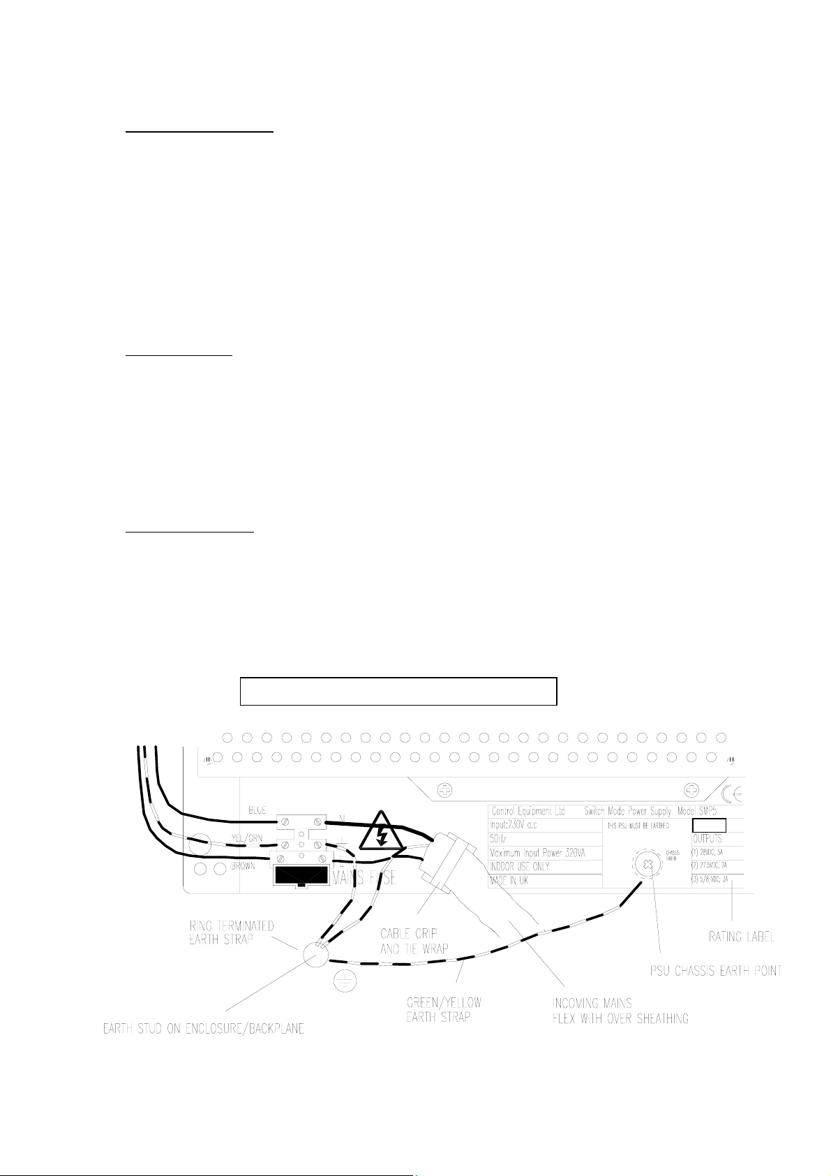
Earthing Arrangement.
It is recommended that the incoming Mains primary earth conductor is connected to a Stud or similar
permanent fixed earth point on the intended p.s.u enclosure. The power supply must also be earthed.
Additional earth connections must be made to the power supply chassis from the enclosure earth stud.
There is an earth point connection on the Mains Terminal Block and also an M3 tapped hole (8mm
depth) is available to allow for a ring terminated earth strap to be attached to the p.s.u chassis. It is
recommended that the primary earth is connected to the enclosure earth stud. An earth strap should
then be connected between enclosure earth stud and the psu chassis.
FIGURE 2. Recommended Earthing arrangement
Document Ref: O&M15845T.DOC/Rev 0 22.11.99 Page 7 of 8 Originator KP Checked By Approved By

Cable Entries
Gland the installation wiring into the enclosure using the cable entry points as applicable.
Connect the 230Va.c input to the Mains Terminal Block as shown in Figure 2. A Mains cable grip is
provided on the p.s.u chassis which utilises a tie wrap arrangement.
8. Commissioning.
The following procedure is to be followed to safe guard equipment and prevent personal injury. The
equipment uses dangerous voltages and stores electrical energy, therefore commissioning and testing
must be carried out by qualified personnel.
All electrical installation and testing must be carried out in line with BS7671: 1992.
Commissioning Procedure
1. Carry out visual inspection and carefully check for any damage, which may have occurred
during transit.
2. Equipment should first be checked to ensure that any connections, which may have become
loose during transit are tightened.
3. Ensure that all external cables to be connected to equipment are suitably rated. Also check that
all cable glands are correctly earthed.
As a minimum:
i) Carry out a visual inspection of the installation for compliance to the regulations and
is free of damage.
ii) Check the protective conductor continuity.
iii) Measure insulation resistance
iv) Verify the polarity of the conductors.
v) Measure the earth loop impedance.
vi) Test the operation of any ELCBs.
(refer to BS7671 for full details)
4. Please note megger test equipment is not permitted to be used while connected to the
power pack, otherwise will cause serious damage to internal components.
5. As the equipment relies primarily on natural convection for cooling purposes, it is important
that the enclosure is checked / sited in a position with a free flow of air. This also applies to
equipment fitted with cooling fans.
6. Connect the A.C mains supply to the mains terminal, making sure to connect to the input
voltage stated in manual. Connect the earth connection to the earth stud provided and check
all other earth points are firmly connected.
7. Before connecting any other external connections remove the mains fuse. Switch on the A.C
mains supply and check supply voltage and polarity are correct. Replace the fuse and check
that the power supply unit indicates the correct indications as per the information contained in
this document. Check power supply D.C output voltages are correct as per the information
contained in this manual.
8. Caution to be exercised when connecting batteries, ensure correct polarity is observed, ensure
correct battery type (2 x 12V sealed rechargeable lead acid) is used.
There are no user serviceable parts and no user functions. All maintenance and repair work must only
be carried out by authorised and fully trained How Fire/C.E.L personnel.
The occurrence of a PSU fault should be indicated at access level 1 (applicable to Fire Alarm System
applications). If a power supply fault is indicated then call the authorised Service/Maintenance
Engineer.
Document Ref: O&M15845T.DOC/Rev 0 22.11.99 Page 8 of 8 Originator KP Checked By Approved By
Table of contents


