HENSCHEL Antriebstechnik DURUMAX TGE User guide

Operating and Servicing Instructions
for
Co-Rotating
Twin Screw Extruder Gearbox
DURUMAX
TGE
DURUMAX
T1MAX
Date: October 2003

Operating and servicing instructions
2 / 24
Table of contents
1 Copyright..................................................................................................................................... 3
2 General instructions .................................................................................................................... 3
3 Safety instructions....................................................................................................................... 4
4 Rating plate ................................................................................................................................. 5
5 As-delivered condition, transport and storage............................................................................. 5
5.1 As-delivered condition and conservation ............................................................................ 5
5.2 Transport............................................................................................................................. 6
5.3 Storage................................................................................................................................ 6
6 Installation ................................................................................................................................... 6
6.1 General installation instructions .......................................................................................... 6
6.2 Foundation........................................................................................................................... 7
6.3 Shafts .................................................................................................................................. 7
6.4 Shaft seals........................................................................................................................... 8
6.5 Sleeves for coupling on the output...................................................................................... 8
6.6 Input clutches ...................................................................................................................... 9
6.7 Belt pulleys.......................................................................................................................... 9
6.8 After installation................................................................................................................... 9
7 Oil system.................................................................................................................................. 10
8 Commissioning the gearbox...................................................................................................... 10
8.1 Filling with lubricant........................................................................................................... 10
8.2 Checking the gearbox ....................................................................................................... 11
8.3 The first run ....................................................................................................................... 11
8.4 Monitoring the torque ........................................................................................................ 11
8.5 Monitoring the axial load ................................................................................................... 12
9 Operation................................................................................................................................... 12
10 Down times................................................................................................................................ 12
11 Technical description................................................................................................................. 13
11.1 General description ........................................................................................................... 13
11.2 Housing ............................................................................................................................. 13
11.3 Gear parts and shafts........................................................................................................ 13
11.4 Bearings ............................................................................................................................ 13
11.5 Seals.................................................................................................................................. 13
11.6 Lubrication......................................................................................................................... 13
11.7 Noises................................................................................................................................ 13
12 Servicing and inspection ........................................................................................................... 14
12.1 Servicing table................................................................................................................... 14
12.2 Topping up the oil.............................................................................................................. 15
12.3 Changing the oil................................................................................................................. 15
12.4 Inspection.......................................................................................................................... 16
13 Malfunctions – causes and rectification .................................................................................... 17
14 Lubricants.................................................................................................................................. 18
14.1 Recommended lubricant - mineral oil................................................................................ 19
14.2 Recommended lubricant – Poly-Alpha Olefin (PAO) ........................................................ 20
14.3 Ordering addresses for recommended lubricant suppliers ............................................... 21
15 Spare parts................................................................................................................................ 23
Table of contents

Operating and servicing instructions
3 / 24
1 Copyright
The copyright to these operating and servicing instructions lies with Henschel Industrietechnik.
These operating and servicing instructions contains instructions and drawings of a technical nature
that are not allowed to duplicated, distributed or used for competitive purposes, or provided to oth-
ers, either in full or in part.
Henschel Antriebstechnik
Henschelplatz 1
D-34127 Kassel
Tel.: +49 (0)561/801-6118
Fax.: +49 (0)561/801-6711
Mail: Antriebstechnik@Henschelgroup.com
2 General instructions
The complete technical documentation is always to be kept near the machine. Errors on the gear-
boxes can only be avoided and correct operation ensured with adequate knowledge of the operat-
ing and safety instructions.
•Every person who is involved in the installation, operation, servicing and repair of the gearbox
must have read and understood the operating and servicing instructions, and must also observe
the operating instructions. We accept no liability for damage and malfunctions in operation that
are caused by failure to observe the operating instructions. In case of doubt, the original Ger-
man version of the operating and servicing instructions is legally binding.
•We reserve the right to make changes to individual modules and accessories compared to the
illustrations and information given in these operating and servicing instructions as necessary for
the improvement of the gearbox.
•The gearboxes are designed for the application that is given in the gearbox datasheet in these
operating and servicing instructions. These operating and servicing instructions can be supple-
mented with additional agreements and instructions. Operation in a different application is not
allowed.
•Before the gearbox is used outside the contractually defined application, after sales service is to
be consulted as otherwise the warranty will be void. Different operating conditions require new
contractual agreements.

Operating and servicing instructions
4 / 24
3 Safety instructions
All work on the gearboxes is to be performed while paying special attention to the aspect of "health
and safety". It is to be refrained from working in any way that endangers the safety of persons and
the gearbox. The gearbox is only allowed to be operated, serviced and repaired by authorized,
trained and appropriately instructed personnel. Work on the gearboxes by unauthorized persons is
to be prevented by the operating organization.
•The applicable regulations for health and safety, the prevention of accidents and the protection
of the environment apply.
•It is imperative that information on the gearbox such as the direction of rotation arrows, rating
plates and the like is observed.
•Rotating input and output components such as couplings, gearwheels, belt drives and the like
must be protected against accidental contact by means of appropriate safety guards.
•Prior to commissioning it is to be checked whether all safety guards are fitted.
•It is not allowed to perform any welding work on the gearbox. The gearbox is also not allowed to
be used as an earthing point for welding work. Damage to the gear teeth or bearings could re-
sult.
•It is not allowed to clean the gearbox with high-pressure cleaning equipment.
•All work on the gearbox is only allowed to be performed when the gearbox is stationary. The
drive unit must be secured against inadvertent switch on.
•The operating organization has the obligation to only operate the gearbox when it is in correct
working order. The drive unit must be switched off immediately if changes on the gearbox are
noted during operation, e.g. elevated operating temperatures, changes in the noises from the
gearbox or leaks.
•Spare parts are always to be procured from Henschel Industrietechnik.
•Unauthorized modifications and changes that affect the safety or function of the gearbox are not
allowed.
•When changing the oil, the used oil is always to be collected in a container. Any oil spills are to
be removed immediately.
•Conservation agents are to be stored separately to used oil.
•Conservation agents, oil binding agents, used oil and oil-soaked cloths are to be disposed of in
accordance with the applicable regulations for the protection of the environment.
The operating organization is responsible for the correct installation of the gearbox. It is a
prerequisite for the assured properties of the gearbox and acceptance of any warranty
claims that the instructions in these operating and servicing instructions are observed.
Observance of the manufacturer's instructions in these operating and maintenance instruc-
tions is a prerequisite for the acceptance of warranty claims.
The performance and properties of the gearbox stated by the manufacturer can only be pro-
vided on observance of the stipulated handling and servicing.
Operating and servicing instructions
5 / 24
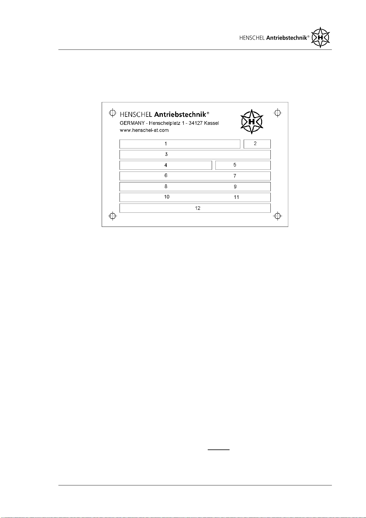
4 Rating plate
The rating plate on the Henschel Industrietechnik twin screw extruder gearbox includes key techni-
cal data. Other data is to be found in the assembly drawings and any technical data sheets en-
closed.
1 Type
2 Year of manufacture
3 Factory number
4 Rating (kW)
5 Weight (kg)
with attachment parts and without oil
filling
6 Input speed (min
-1
)
7 Transmission ratio
8 Lubricants in accord. with DIN 51 517
9 Oil capacity (l)
10-12 Additional information on possible
axial force measurement and torque
monitoring
•When making queries, it is imperative that the information on the rating plate is supplied
•The rating plate is not allowed to be removed; it is to be kept clear of dirt and paint. Missing
plates must be replaced without delay
5 As-delivered condition, transport and storage
5.1 As-delivered condition and conservation
All twin screw extruder gearboxes are subject to a test run and acceptance prior to delivery. Ac-
ceptance is performed in accordance with Henschel regulations or as per the related requirements
agreed in the contract. The paint finish on the interior and exterior of the gearbox comprises a thick-
film epoxy metal primer RAL 7032 (pebble grey). The manufacturer reserves the right to use other
products in special cases. An additional topcoat can be agreed. All bare exterior parts and surfaces
are coated with a wax conservation agent, e.g. Tectyl 846. The conservation on the exterior of the
gearbox is to be removed using suitable means. During this process the corresponding regulations
on waste disposal are to be observed. The conservation inside the gearbox is matched to the type
of oil given in the gearbox data sheet. It is not necessary to remove the conservation agent inside
the gearbox. Given proper storage, the conservation is effective for 6 months. For longer periods of
storage, the conservation inside the gearbox and on the exterior is to be checked and renewed if
necessary.
The gearboxes are delivery ready to use, however without oil filling. Prior to commissioning,
the gearboxes are to be filled with a suitable lubricant (see information on the gearbox data
sheet).

Operating and servicing instructions
6 / 24
5.2 Transport
The gearbox is packed to suit the type of transport such that it can be transported without damage.
The gearbox is equipped with holes for ring bolts as per the installation drawing. Appropriate ring
bolts are to be fitted such that they are tight against the bearing surface. On some models, special
hooks for lifting tackle are fitted to the lower part of the housing.
The ends of shafts and attachment parts such as pipes and coolers are not allowed to be
used for transport.
For transport, ropes with adequate carrying capacity are to be attached to the ring bolts/hooks (the
weight of the gearbox is to be taken from the rating plate or the gearbox data sheet). For types with
an adapter housing, the ropes can be placed through the opening on the adapter housing.
•Only the ring bolts or the hooks are designed for the transport of the gearbox. Transporting the
gearbox using attachment parts already fitted is not allowed.
•It is only allowed to lift and set down the gearbox using suitable lifting gear.
•All transport aids fitted are to be used. During transport the gearbox is be kept horizontal so that
all points are evenly loaded.
•During transport it is to be ensured that any attachment parts, e.g. pumps, coolers or pipes are
not damaged.
•Transport is to be performed with extreme care to avoid injury. Damage to the gearbox, e.g. due
to impacts on the open ends of shafts or due to setting down hard is to be avoided.
5.3 Storage
Proper storage of the gearbox will prevent premature damage and problems during later commis-
sioning.
•The gearbox is to be stored in place free of vibration and protected from the weather.
•Vibrations and shocks can cause damage. Moisture and other substances can impair the func-
tionality of the gearbox.
•It is not allowed to stack gearboxes on top of each other.
•The gearbox and the attachment parts are to be protected from mechanical, chemical and
thermal damage, as these can cause corrosion.
6 Installation
6.1 General installation instructions
During the installation of the gearbox, it is imperative that the instructions in section 3 "Safety in-
structions" are observed. Damage cause by incorrect installation is excluded from the warranty.
•Installation is only to be performed by trained, authorized and appropriately instructed person-
nel.
•The gearbox is to be installed in a suitable place such that there is sufficient space for the in-
stallation work and subsequent servicing work.

Operating and servicing instructions
7 / 24
•Oil drain and oil level gauge must be easily accessible.
•The gearbox is to be protected from strong sunlight so avoid over-heating.
•During transport, it is imperative that the instructions in section 5.2 are observed.
•Bangs and knocks are to be avoided, as these can damage shafts, bearings, gears and seals.
6.2 Foundation
•The gearbox is to be installed on a flat, rigid and torsionally stiff foundation. The foundation
must be designed such that there are no resonances and no vibration/shocks can be picked up
from other foundations. When installing the gearbox, it is imperative that the directive VDI 2726
"Ausrichten von Getrieben" (Aligning Gearboxes) is observed.
•Prior to installation, the underside of the gearbox feet and the foundation frame are to be
cleaned.
•The gearbox is, depending on the type, to be attached to the foundation at all the fastening
points provided for this purpose.
•It is imperative that the mounting position agreed in the order is maintained. An incorrect
mounting position can result in inadequate lubrication and thus to complete failure.
•Fastening bolts must have a minimum strength class of 8.8.
•The gearbox is not allowed to be placed under stress when the fastening bolts are tightened.
•The alignment of the gearbox must be re-checked after tightening the fastening bolts.
•If external forces act on the gearbox, it is appropriate to prevent movement using lateral stops.
•All fastening features on the gearbox are to be utilized.
6.3 Shafts
•The coating of conservation agent applied to the shafts is to be entirely removed using an ap-
propriate, approved cleaning agent. During this process appropriate ventilation is to be pro-
vided. ATENTION, risk of explosion.
•It is to be ensured that the shaft sealing rings are not wet with the solvent when removing the
conservation agent, as otherwise leaks may result.
•Input and output parts (e.g. couplings) are to be tightened and locked. Here suitable devices are
to be used. Shaft seals and their contact areas on the shaft must not be damaged.
•Fitting couplings or other attachment parts by hitting or striking is not allowed as this can result
in damage to the bearings, gears and seals.
•If heating is necessary for fitting attachment parts, this can be performed inductively, with a gas
torch, or in an oven. It is to be ensured that the shaft seals are protected from damage and from
heating to more than +100°C during this process.

Operating and servicing instructions
8 / 24
6.4 Shaft seals
The shafts are sealed with single or double shaft seals. On certain types, labyrinth seals, special
cassette seals or a combination of various systems can also be used.
•The shaft seals must not come into contact with solvents or unsuitable cleaning agents, as this
can result in leaks.
•Corrosion on the shaft due, for example, to high atmospheric humidity limits the life of the shaft
seals.
•During painting, the shaft seals and the contact areas are to be masked using suitable means.
Remnants of paint are not allowed in the area of the seal, as they can cause damage and thus
leaks.
•The operating temperatures stipulated on the gearbox data sheet are not allowed to be ex-
ceeded, as elevated operating temperatures can cause premature damage to the seals.
•The shaft seals must be protected from the mechanical action of tools or other objects.
•Replacement seals are to be procured from Henschel Industrietechnik. We only guarantee
spare parts that we have supplied. A warranty is only provided for the spare parts supplied by
the manufacturer.
6.5 Sleeves for coupling on the output
Sleeves for coupling are used to adapt the extruder screws to the gearbox. The design and align-
ment of the sleeves for coupling is customer and gearbox-specific. The related items are to be
found on the installation drawing.
It is not possible to interchange sleeves for coupling from different gearboxes.
•For the adaptation of the two extruder screws, the two sleeves for coupling must be placed in
the corresponding position as per the installation drawing. If not otherwise requested, Henschel
Industrietechnik will supply the gearbox with matched sleeves for coupling.
•The two sleeves for coupling must always remain with the related gearbox because they have
been specially matched to the related gearbox.
•In the case of damage to the gearbox, the sleeves for coupling are also to be returned to the
gearbox manufacturer.
•The sleeves for coupling are only allowed to be matched to the gearbox using the alignment
device for this purpose and by trained personnel.
•The factory number and the sequential gearbox number are used for identification. As a rule,
the two sleeves for coupling are also marked with the letters R and L (right and left in the direc-
tion of extrusion).
•The reference surfaces on the two output shafts are aligned under axial loading. The tolerances
on the alignment are to be found in the installation drawing. In the unloaded state, the toler-
ances given may be exceeded due to the pre-tensioning forces in the springs.

Operating and servicing instructions
9 / 24
6.6 Input clutches
Safety clutches are to be used for the gearbox input. The use of rigid couplings or other input ele-
ments that can exert radial and/or axial forces must be agreed with Henschel Industrietechnik. The
contractually assured type of input is to be found in the gearbox data sheet.
When using clutches, the following is to be observed:
•Drive unit and gearbox must be accurately aligned. Incorrect axle or angular offset can result in
premature failure. The limits from the supplier of the clutch apply.
•From a peripheral speed of 30m/s at the outside diameter on the clutch, dynamic balancing is
required. Here the information from the clutch manufacturer must be observed.
6.7 Belt pulleys
For certain types, it is possible to provide drive using a belt pulley.
A belt pulley is only allowed to be used if this input variant is recorded in the gearbox data
sheet.
The unauthorized fitting of a belt pulley can result in shafts shearing, bearing and gear damage.
•Belt pulleys are to be fitted to the end of the input shaft with the aid of thrust plates and bolts
using thread centering or by other suitable means.
•Fitting by hitting and striking is not allowed as parts inside the gearbox may be damaged in this
way.
•The maximum permissible belt tension (force applied at the middle of the key) must not be ex-
ceeded, as otherwise the input shaft may be subject to excessive bending and damage caused
to the bearings and seals. The values given in the gearbox data sheet are general figures. In
case of doubt, consult Henschel Industrietechnik.
•The belt is only allowed to be tensioned in the directions given by Henschel Industrietechnik.
Failure to observe this instruction can result in premature damage. In case of doubt, consult
Henschel Industrietechnik.
•Belt tension must always be applied at the middle of the key. The use of excessively wide belt
pulleys is to be avoided.
•The holes on the belt pulleys used should not have sharp edged transitions at the front face.
Belt pulleys with rounded transitions reduce stressing at the edges and thus help to prevent
damage to the input shafts.
•Following installation, the V-belt is to be protected against accidental contact by means of a
suitable safety guard.
6.8 After installation
•Following installation, all rotating parts are to be protected against accidental contact by means
of suitable safety guards.
•Any guard supplied, if removed, must be re-fitted.
•By referring to the delivery paperwork and the assembly drawing, it is to be checked whether all
devices that may have been removed from transport or other reasons have been re-fitted.

Operating and servicing instructions
10 / 24
7 Oil system
The gearbox is to be connected to a suitable oil system. The necessary data are to be found in the
gearbox data sheet in these operating and servicing instructions. Suction and pressure connections
are fitted to the gearbox in the form of threaded holes. The position and the connection data are to
be found in the installation drawing.
•The threaded holes are sealed with plugs for transport. These plugs are to be retained and re-
fitted if the gearbox is removed.
•It is to be checked whether all monitoring devices fitted to the oil system function correctly.
•The oil system must comply with the technical requirements listed in the gearbox data sheet.
•The system is to be equipped with pressure switches for monitoring the oil pressure, if the oil
pressure drops below 0.5bar the main motor is to be shut down.
•The temperature of the oil is to be monitored. For fitting a temperature sensor, depending on
the order, there is a threaded hole G1/2" in the lower part of the base gearbox housing.
•The oil filter must have the filter mesh required in the gearbox data sheet and be tested for cor-
rect function.
•The system is to be checked for oil leaks at operating temperature.
•All threaded fittings are to be checked for tightness.
8 Commissioning the gearbox
When commissioning the gearbox, it is imperative that the instructions in section 3 "Safety instruc-
tions" are observed.
•Prior to commissioning, the rest of the conservation oil or the running-in or test oil is to be
drained from the gearbox and disposed of in accordance with regulations.
•Flushing with petrol or other cleaning agents is forbidden, as the residue left in the gearbox can
cause decomposition.
8.1 Filling with lubricant
Prior to commissioning, the gearbox is to be filled with fresh oil via the threaded hole for the vent
screw or via the inspection holes.
When filling the gearbox, the lubricant is to be filtered with the aid of a funnel with filter (filter
mesh 40µm). Dirty oil can cause premature damage to bearings and gears.
•Only the lubricants given in the attached lubricant table (section 14) for twin screw extruder
gearboxes from Henschel Industrietechnik are allowed to be used. The use of other lubricants is
only allowed following consultation and agreement with Henschel Industrietechnik.
•The approximate oil capacity, the oil type and the oil viscosity are to be found in the instructions
on the rating plate.

Operating and servicing instructions
11 / 24
•The oil capacity given on the gearbox rating plate is an approximate quantity. The gearbox is to
be filled until the oil is at least up to the middle of the oil sight glass.
•To ensure that the oil level is correct, after filling with lubricant the oil system is to be placed in
operation for approx. 5 minutes. If the oil level drops during this process, the oil is to be topped
up.
•Any oil spilt is to be removed immediately with an oil binding agent.
•After filling, the air filters are to be re-fitted and the inspection holes securely closed.
It is imperative to ensure that no dirt enters the gearbox during an oil change.
8.2 Checking the gearbox
Prior to initial commissioning, the gearbox is to be carefully inspected to avoid damage due to incor-
rect installation.
•All mechanical parts, e.g. inspection hole covers, guards, foundation threaded fittings and oil
supply pipes must be tight.
•Check the oil level at the oil sight glass.
•There must not be any leaks on the gearbox.
•All supply pipes must be correctly connected.
•The gearbox must be securely fastened to the foundation (section 6.2).
•All rotating parts must be covered in accordance with regulations and secured against acci-
dental contact (section 3).
8.3 The first run
The gearbox can only be operated in one direction of rotation (see installation drawing and gearbox
data sheet).
Operation in the opposite direction of rotation is not allowed.
The gearbox is only allowed to be placed in operation and operated when the oil system is
running.
If the oil system fails, the gearbox is to be shut down immediately.
The lubricant in the oil system must be pre-heated to the minimum operating temperature. It
is recommended to leave the oil system running for at least 10 minutes prior to starting the
drive unit. Here it is to be ensured that inadmissible foaming does not occur.
8.4 Monitoring the torque
Henschel Industrietechnik twin screw extruder gearboxes can transmit very high torques via the two
output shafts. The maximum permissible torques are to be found in the gearbox data sheet.
It is possible to monitor the torques at the output shafts with the aid of torque measuring shafts. The
shafts are checked and calibrated. The calibration log is included with the gearbox. The part num-
bers for the measuring shafts as well as the number of the calibration log are noted on the rating
plate.

Operating and servicing instructions
12 / 24
8.5 Monitoring the axial load
The twin screw extruder gearboxes built by Henschel Industrietechnik can absorb high axial thrust
loads on both output shafts. The maximum permissible thrusts and the thrust loads are to be found
in the gearbox data sheet.
Depending on the order, the gearbox can be supplied with axial force monitoring. The forces are
monitored using a load cell or a bonded strain gauge. All measuring devices are checked in ad-
vance and calibrated. The calibration log is included with the gearbox.
The type of axial force monitoring is to be found on the rating plate. The number of the calibration
log is also noted here. On the use of load cells, the serial number is also given.
9 Operation
It is to be ensured that the performance data and parameters in the data sheet and on the rating
plate are observed. Only in this way is the reliability and long service life of the gearbox assured.
•If the gearbox is equipped with an oil supply system, the gearbox is never allowed to be placed
in operation without the oil supply system running.
•The servicing work listed in section 12.1 must be performed conscientiously.
•An exact oil level check is only possible with the system stationary. When the oil is warm the oil
level can be somewhat higher. It is not allowed to let the oil level drop below the minimum mark
– in this case the oil must be topped up (section 12.2).
If irregularities occur during the operation, the system is to be shut down immediately. The cause of
the malfunction is to be determined and rectified before the gearbox is placed back in operation.
Section 13 provides an overview of the possible causes of malfunctions and their rectification. If the
reason for the malfunction cannot be correctly determined, after sales service at Henschel Indus-
trietechnik is to be contacted.
10 Down times
During down times of several months, the gearbox is to be run at no load and nominal speed for a
short time every approx. 4 weeks. If this is not possible, the gearbox must be protected with a suit-
able conservation agent. Henschel Industrietechnik after sales service will provide assistance with
the interior and exterior conservation.
Storage for more than 24 months can result in degradation of the gearbox components. In these
cases it is advisable to consult Henschel Industrietechnik.

Operating and servicing instructions
13 / 24
11 Technical description
11.1 General description
These operating and servicing instructions only apply to twin screw extruder gearboxes manufac-
tured by Henschel Industrietechnik. The gearboxes described are spur gearboxes with one input
shaft and two output shafts as marketed by Henschel Industrietechnik with the identifier TGE or
T1MAX.
11.2 Housing
All housing parts comprise thick-walled grey cast iron with optimized internal ribbing. If necessary,
certain parts may also be manufactured from steel. The housing parts are joined together using
bolts and alignment dowels. The torsion resistant design has optimized noise behavior. Inspection
hole covers on the top of the gearbox enable the gears to be checked. An oil sight glass enables
the oil level to be checked.
11.3 Gear parts and shafts
The gear parts are manufactured from high-alloy hardened steel, case hardened, ground and de-
signed for durability. High contact ratios and high gear quality ensure low noise running.
The transmission of torque from the spur gears to the shafts is force-locked. The shafts are manu-
factured from high-alloy heat treated steel and transmit the torque with adequate safety.
11.4 Bearings
All shafts have bearing at both ends. Axial bearings of varying types are used for absorbing the
axial forces from the screws. The minimum theoretical bearing service lives for the roller bearings
and the thrust bearings are given in the gearbox data sheet. These are calculated based on the
nominal torque and nominal speed. Collective load, impacts and lubricant effects are not taken into
account here.
11.5 Seals
The inspection hole covers are sealed with an asbestos-free gasket, the bearing surfaces for all
other covers and housing joints are sealed with a durable sealant. The shafts are sealed with single
or double shaft seals. On certain types labyrinth seals, special cassette seals or a combination of
various systems are used.
11.6 Lubrication
A combined splash and forced-feed circulatory lubrication system supplies the gearbox with suffi-
cient oil. Internal pipework feeds the oil to the meshing gears and the roller bearings. The gearbox
housing also serves as an oil reservoir to which the oil filler openings, oil drain plug and oil level
gauge are fitted.
11.7 Noises
Sound pressure levels have been measured at the gearboxes for the operating conditions stated in
the gearbox data sheet. The magnitude of the sound pressure level is to be found in the gearbox
data sheet.

Operating and servicing instructions
14 / 24
12 Servicing and inspection
Malfunctions that are caused by inadequate or improper maintenance can result in high repair costs
and unnecessarily long gearbox down times. Regular servicing and inspection work are therefore
imperative.
All servicing and repair work is only allowed to be performed with the gearbox stationary and by
trained, authorized and appropriately instructed personnel. It is imperative that all safety instructions
(section 3) are observed.
12.1 Servicing table
Work to be performed Frequency Comment
Check the oil temperature daily Excessively high temperatures are a sign of
malfunctions or damage to the gearbox or the oil
system. They reduce the service life of the oil and
can result in the premature failure of the gearbox
Check the noise made by
the gearbox for changes daily Changes in the noises made by the gearbox can
be indicative of damage to the parts inside the
gearbox
Check the oil level weekly An oil level that is too low can result in inade-
quate lubrication of the gearbox and thus to fail-
ure of bearings or gears
Check the gearbox for
leaks monthly Leaks that go unnoticed can result in inadequate
lubrication
First oil change after approx. 250
operating hours See section 12.3
Subsequent oil change every 4000 to
8000 operating
hours, at the
latest however
after 12 months
See section 12.3
Visual inspection of the
gears quarterly The visual inspection of the gears can be per-
formed by removing the inspection hole covers.
In case of damage or irregularities, the manu-
facturer must be consulted
Check used oil for foreign
bodies and coloration quarterly Unusually high quantities of foreign bodies, e.g.
metal particles can be indicative of damage.
Coloration is a sign of reduced quality oil
Clean the air filter quarterly Regular cleaning with suitable cleaning agents
prevents clogging of the filter
Check the oil filter quarterly (daily
with autom. dis-
play)
Unusually high quantities of foreign bodies, e.g.
metal particles can be indicative of damage, it is
then necessary to replace the filter
Check the oil viscosity class before every oil
change The viscosity is to be found on the rating plate
and the gearbox data sheet
Clean the gearbox housing after every oil
change Prevents premature aging and undesirable corro-
sion
Check all fastening bolts annually Checking all fastening bolts for tightness in-
creases safety and reliability
Service the complete gear-
box Every 2 years Regular servicing by Henschel Industrietechnik
after sales service enables worn parts to be re-
placed in a timely manner and thus ensures long
gearbox service life

Operating and servicing instructions
15 / 24
12.2 Topping up the oil
The oil level is to be checked regularly. It must never be below the bottom mark. In the case that the
oil level drops below the minimum, it is imperative that the lubricant is topped up. The oil is only
allowed to be topped up with the drive units shut down.
•A funnel with a filter is to be used for topping up (filter mesh 40µm).
•The gearbox is always to be filled with the same type of oil as used previously (see section 8.1).
It is not allowed to mix different oils or oils from different manufacturers.
12.3 Changing the oil
The effectiveness of the oil reduces with increasing use due to soiling (foreign bodies and water)
and chemical changes (ageing products). When the soiling and/or ageing is/are excessive, it is
necessary to change the oil. Regular oil analyses provide information on the effectiveness of the
gearbox oils. For larger quantities of oil it is recommended to make oil changes dependent on the
results of an oil analysis. A missed oil change increases the risk of damage and can result in pre-
mature failure of the gearbox.
The first oil change should be made at approx. 250 operating hours. Subsequent oil changes de-
pend on the state of the oil and are to be performed every 4,000 to 8,000 operating hours, however
at the latest after one year.
•As a matter of principle the gearbox is always to be filled with the type of oil used previously. It
is not allowed to mix different oils or oils from different manufacturers.
•A funnel with a filter must be used to fill the gearbox (filter mesh 40µm). Dirt can result in pre-
mature damage to bearings and gears.
•When changing the oil, the old gearbox oil is to be drained, if possible when still warm, using
the oil drain plug provided for this purpose.
•The drained gearbox is to be cleaned of oil sludge, dirt and remnants of old oil using flushing oil.
The same type of oil is to be used here.
•On every oil change the oil drain plug is to be cleaned. If the plug is very dirty, the source of the
dirt is to be determined. There may be damage.
•Also, on every oil change the filter element in the oil filter is to be cleaned or replaced, as a dirty
filter can degrade the reliable function and expected service life of the gearbox and the oil sys-
tem.
•The gearbox vent filter is also to be cleaned.
•All instructions in section 8.1 are to be observed.
•When the oil is changed, all tooth flanks are to be visually inspected. In case of damage or ir-
regularities, the manufacturer is to be consulted.
•When refilling the gearbox, it is to be ensured that the oil level is in the area marked on the oil
sight glass. To ensure that the oil level is correct, after filling the oil system is to be placed in
operation for approx. 5 minutes so that the fresh oil can fill the pipes and the cooler. If the oil
level drops, the oil is to be topped up.
It is imperative to ensure that no dirt enters the gearbox during the oil change.

Operating and servicing instructions
16 / 24
12.4 Inspection
To counteract damage on the gearbox, regular inspections should be performed. The after sales
service department at Henschel Industrietechnik offers the following checks:
•Checking the contact pattern on the individual teeth,
•Checking whether there is any damage to the parts of the gears, e.g.:
- Pittings and micro pittings on the tooth flanks (due to gearbox overloading)
- Scratches and indentations (due to the action of dirt)
- Fretting (due to inadequate lubrication or overload)
•Visual inspection of the roller bearings
•Checking the oil supply to the meshing gears and to the roller bearings in the gearbox
In case of damage, the related parts are replaced. Malfunctions are rectified. Please contact our
after sales service department.

Operating and servicing instructions
17 / 24
13 Malfunctions – causes and rectification
Regular servicing of the gearbox, as described in section 12, is imperative. It is only in this way that
irregularities can be detected and more serious consequent damage avoided. If malfunctions occur
during the warranty period and repair is necessary, the after sales service department at Henschel
Industrietechnik is to be contacted. For repairs that were not approved by Henschel Industrietech-
nik, no warranty or guarantee for the subsequent operation of the gearbox can be provided.
The rectification of malfunctions is only allowed to be performed with the gearbox stationary and by
trained personnel. It is imperative that all safety instructions (section 3) are observed.
Possible malfunctions:
Malfunctions Causes Rectification
Oil level is too high Check oil level and adjust
Oil is too old Check when the oil was last changed and if nec-
essary have the oil analyzed and change the oil
Oil is very dirty Change the oil
Cooling is insufficient Check the cooling system feed and return, if nec-
essary increase the cooling (higher flow of cool-
ing water, lower temperature)
Oil flow rate is inade-
quate Check the feed and return, clean oil filter or re-
place
Elevated oil tem-
perature
Oil pump is faulty Check pump, if necessary replace
Oil level is too low Check oil level and adjust
Oil is too old Check when the oil was last changed and if nec-
essary have the oil analyzed and change the oil
Bearing faulty Seek advice from Henschel Industrietechnik after
sales service
Elevated bearing
temperature
Oil pump faulty Check pump, if necessary replace
Noises Bearing or gear dam-
age Seek advice from Henschel Industrietechnik after
sales service
Inadequate fastening to
the foundation Re-tighten bolts, if necessary replace
Leaks Inadequate sealing Check radial shaft seals and other seals, if nec-
essary replace, renew sealing of joints (on this
topic seek advice from Henschel Industrietechnik
after sales service)
Water in the oil Oil cooler faulty Repair/replace oil cooler
Condensed water Fit suitable thermal insulation, close vent, moist
air filter
Elevated quantity of
particles in the oil Bearing or gear dam-
age or faulty oil pump Seek advice from Henschel Industrietechnik after
sales service
Oil foaming Oil incompatible with oil
residue Change the oil
Operating temperature
too low Shut down plant, leave oil to de-gas, pre-heat oil
to operating temperature (if necessary shut off
cooling water feed briefly)
Water in the oil Have the oil analyzed, if necessary change the oil

Operating and servicing instructions
18 / 24
14 Lubricants
The oil types and oil viscosity class stipulated by Henschel Industrietechnik can be found on the
rating plate and the data sheet for the related gearbox. This information applies for the operating
data given in the gearbox data sheet. If these data change, Henschel Industrietechnik in Kassel is
to be consulted prior to commissioning. If a different viscosity class is used or gearbox oil different
to that recommended is used, the responsibility for the technical suitability lies with the operating
organization.
Only CLP quality oils are allowed to be used for our gearboxes. They must comply with the mini-
mum requirements in DIN 51517-3 (draft January 2002). In addition, the oil must have increased
safety against micro pittings. The oils must be suitable for the elastomeric materials in the shaft
seals and the usual gaskets that are used between bolted surfaces.
The use of lubricants that do not comply with the stipulated quality requirements may render the
warranty void.
The mineral oils listed in section 14.1 can be used in a temperature range from –10°C to +90°C
(100°C briefly). For the poly-alpha olefins (sectio n 14.2) the temperature range is between –20°C
and +100°C (110°C briefly).
Lubricants from different manufacturers are never allowed to be mixed together.
Furthermore, flushing with petrol or other cleaning agents is not allowed, as the residue left
in the gearbox can result in decomposition.

Operating and servicing instructions
19 / 24
14.1 Recommended lubricant - mineral oil
Lubricant Mineral oil
Code letter in accordance with DIN 51502 CLP
Identifier in accordance with DIN 51517-3 CLP 220 CLP 320 CLP 460
Identifier in acc. with DIN ISO 3498 CC 220 CC 320 CC 460
ISO viscosity class in acc. with DIN 51519 ISO-VG 220 ISO-VG 320 ISO-VG 460
Kinematic viscosity at 40°C [mm
2
/s] 220 320 460
Manufacturer Degol BG 220 Plus Degol BG 320 Plus Degol BG 460 PlusAral
Degol BMP 220 * Degol BMP 320 * Degol BMP 460 *
Castrol Alpha SP 220 Alpha SP 320 Alpha SP 460
Renolin CLP 220
Plus Renolin CLP 320
Plus Renolin CLP 460
Plus
Fuchs
Renolin CLP 220 Renolin CLP 320 Renolin CLP 460
Mobil Mobilgear XMP
220 Mobilgear XMP
320 Mobilgear XMP
460
Shell Shell Omala F 220 Shell Omala F 320 Shell Omala F 460
Optimol Optigear
BM 220 Optigear
BM 320 Optigear
BM 460
Tribol Tribol 1100/220 Tribol 1100/320 Tribol 1100/460
* High-performance CLP oil with molybdenum disulphide (MoS
2
)

Operating and servicing instructions
20 / 24
14.2 Recommended lubricant – Poly-Alpha Olefin (PAO)
Lubricant Poly-Alpha Olefin (PAO)
Code letter in accordance with DIN 51502 CLP HC
Identifier in accordance with DIN 51517-3 CLP HC 220 CLP HC 320 CLP HC 460
Identifier in acc. with DIN ISO 3498 CC 220 CC 320 CC 460
ISO viscosity class in acc. with DIN 51519 ISO-VG 220 ISO-VG 320 ISO-VG 460
Kinematic viscosity at 40°C [mm
2
/s] 220 320 460
Manufacturer
Aral Degol PAS 220 Degol PAS 320 Degol PAS 460
Castrol Alphasyn EP 220 Alphasyn EP 320 Alphasyn EP 460
Fuchs Renolin Unisyn
CLP 220 Renolin Unisyn
CLP 320 Renolin Unisyn
CLP 460
Mobilgear SHC 630 Mobilgear SHC 632 Mobilgear SHC 634Mobil
Mobilgear SHC
XMP 220 Mobilgear SHC
XMP 320 Mobilgear SHC
XMP 460
Shell Shell Omala HD
220 Shell Omala HD
320 Shell Omala HD
460
Optimol Optigear
Synthetic A 220 Optigear
Synthetic A 320 Optigear
Synthetic A 460
Tribol Tribol 1710/220 Tribol 1710/320 Tribol 1710/460
This manual suits for next models
1
Table of contents


