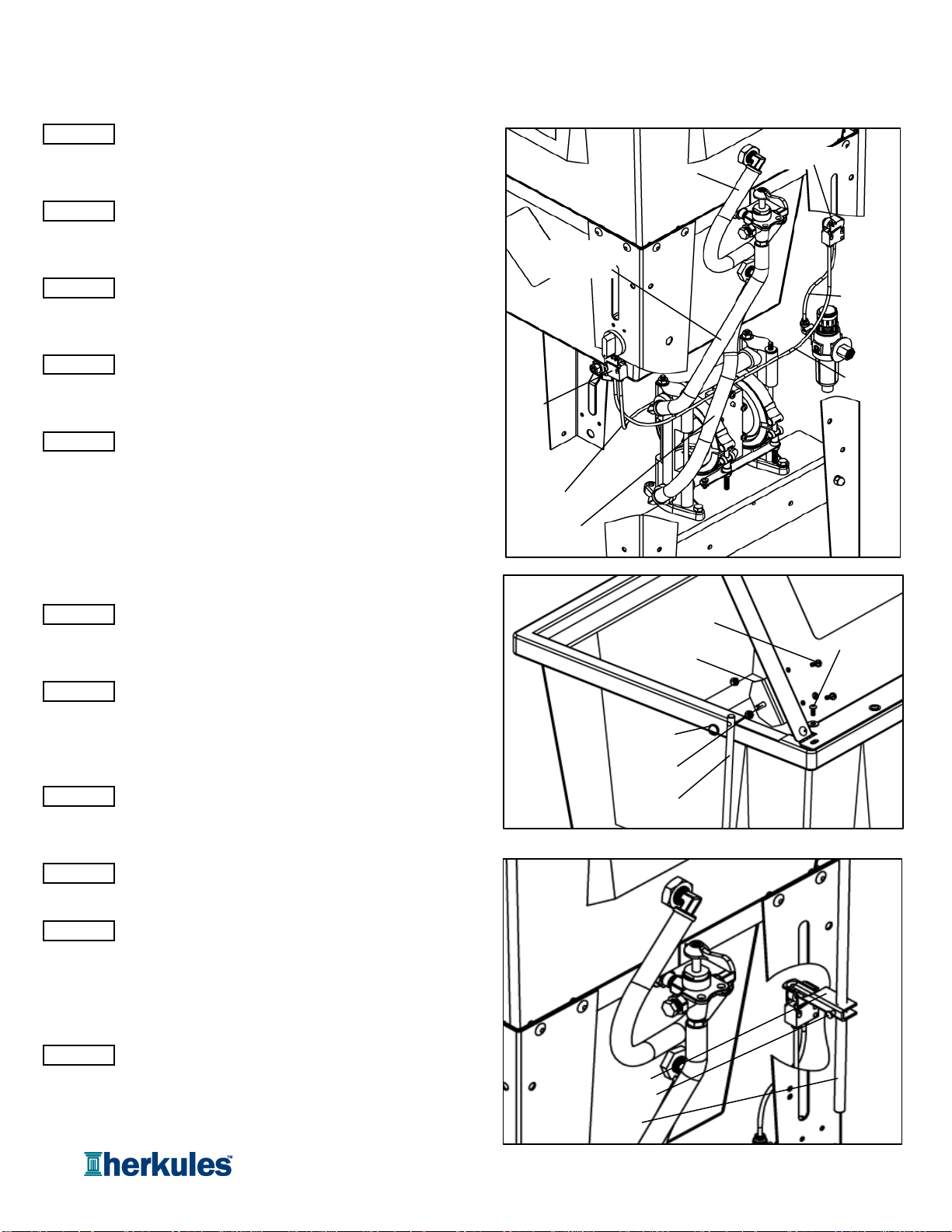
Connecting fluid and air hoses
Insert the nipple and bushing end of the 3-way valve
assembly into the upper bulkhead in the tub. Use sealant
to avoid leaking and orient as shown [see fig.4].
Connect the 13" long fluid outlet tube between the fluid
outlet port of the pump and the straight barb on the valve.
DO NOT HEAT HOSE [see fig.4].
Connect the 16" long fluid inlet tube between the fluid
inlet port of the pump and the lower bulkhead on the tub.
DO NOT HEAT HOSE [see fig.4].
Connect the 20" long fluid tube between the elbow barb on
the valve and the elbow barb on the tub above the valve.
DO NOT HEAT HOSE [see fig.4].
Connect the black 5/32" air hose between the regulator
and the air in port of the limit valve located on the rear leg
of the gun washer [see fig.4].
Note: Air in port of limit valve is the port opposite the roller.
For all air hose, press tubing in through collar until seated.
Pull firmly on hose to test for a tight connection.
Connect the blue 5/32" air hose between the air in port of
limit valve located on the front leg and the air out port of the
limit valve located on the rear leg of the gun washer [see fig.4].
Connect the clear 5/32" air hose between the pump and
the air out port of the limit valve located on the front leg
of the gun washer [see fig.4].
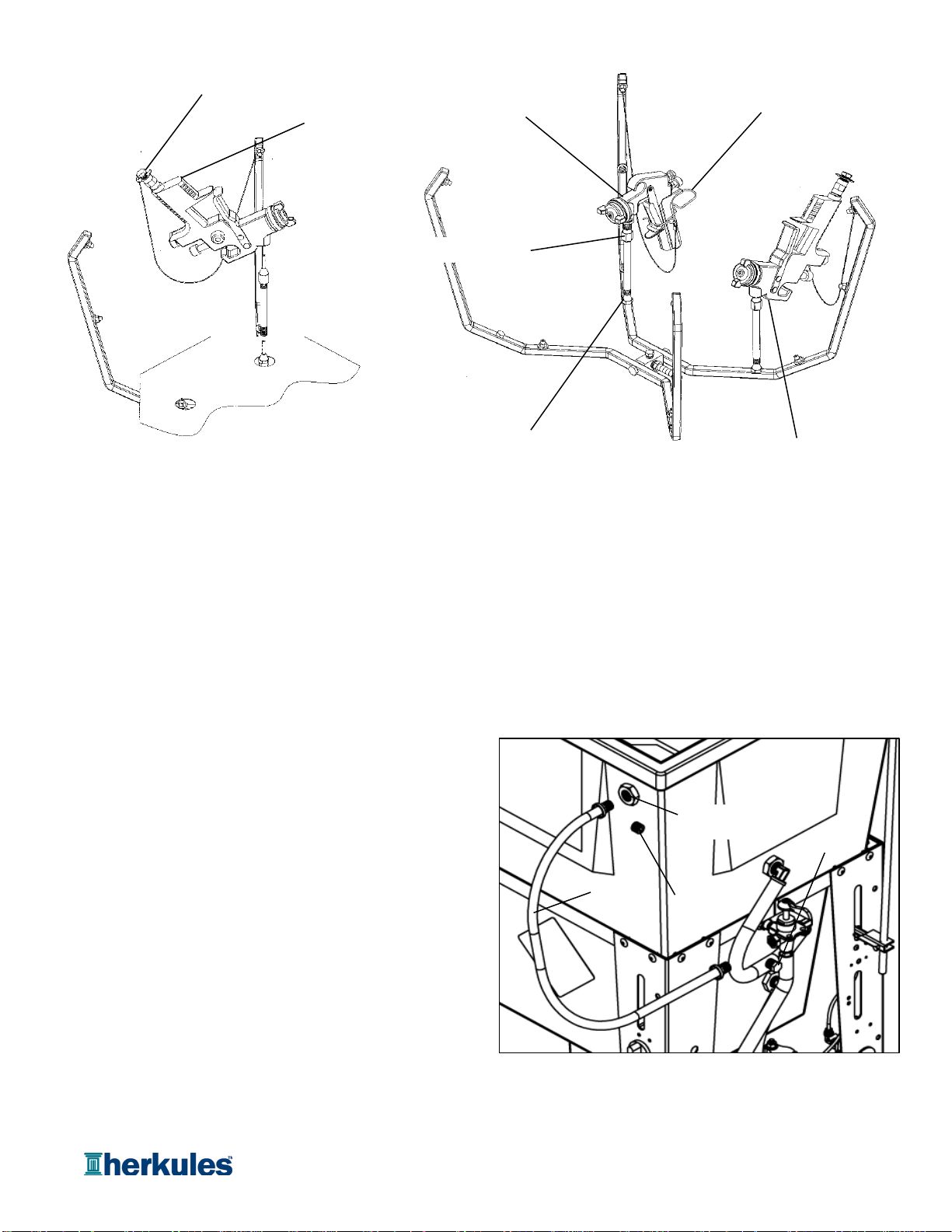
Connecting lid rod and actuator linkage
Slide the actuator over the lid rod opposite the drilled end
and hand tighten approx. 4" from the end of the rod. Insert
the actuator into the large slot in the right rear leg [see fig 6].
Attach the lid rod to the lid bracket using the 1/4" clevis pin
and circular cotter ring supplied [see fig. 5].
To adjust the actuator, close the lid and loosen the set
screw on the actuator. Slide the actuator down until it
completely closes the limit valve and retighten the set
screw [see fig. 6].
Grounding the lid
Using an 1/8" allen wrench, remove the back right lid screw.
Connect the ground wire (with the aluminum terminal
attached) from the pump to the lid screw and reconnect it
to the tub [see fig. 5].
Assembly Instructions
STEP 8
STEP 11
STEP 7
STEP 6
STEP 10
STEP 9
STEP 15
STEP 16
STEP 14
STEP 13
STEP 12
fig.5
Lid screw
Lid rod
Cotter pin
Lid bracket
Clevis pin
Limit valve
Limit
valve
Clear air
hose
13" Fluid
outlet tube
16" Fluid
inlet tube fig.4
Black air
hose
Blue air
hose
fig.6
Lid rod
Actuator
Set screw
20" Fluid
tube
Bracket
screw
Page 8 of 20