herdstar BinTrac HouseLink HL-10C User manual
Installation and Operation Manual
HL-10C Installation Manual Rev 2.0 Part Number MAN-000015
Installation and Operation Manual
HouseLink HL-10C

Installation and Operation Manual
HL-10C Installation Manual Rev 2.0 2Part Number MAN-000015
1400 Madison Avenue, Suite 504, Mankato, MN 56001
PH: 507-344-8005 FAX: 507-344-8009
www.herdstar.com
Table of Contents
Description ..............................................................................................................................................................................3
Installation...............................................................................................................................................................................3
BinTrac Indicator Setup.......................................................................................................................................................4
LED Operation.....................................................................................................................................................................4
CAN Bus Status LED: .....................................................................................................................................................4
BinTrac Status LED:........................................................................................................................................................4
Testing and Calibration...........................................................................................................................................................5
Reset/Test button:...............................................................................................................................................................5
CAN Open Setup ....................................................................................................................................................................5
CAN Classic Setup..................................................................................................................................................................7
Operational Specifications ......................................................................................................................................................8
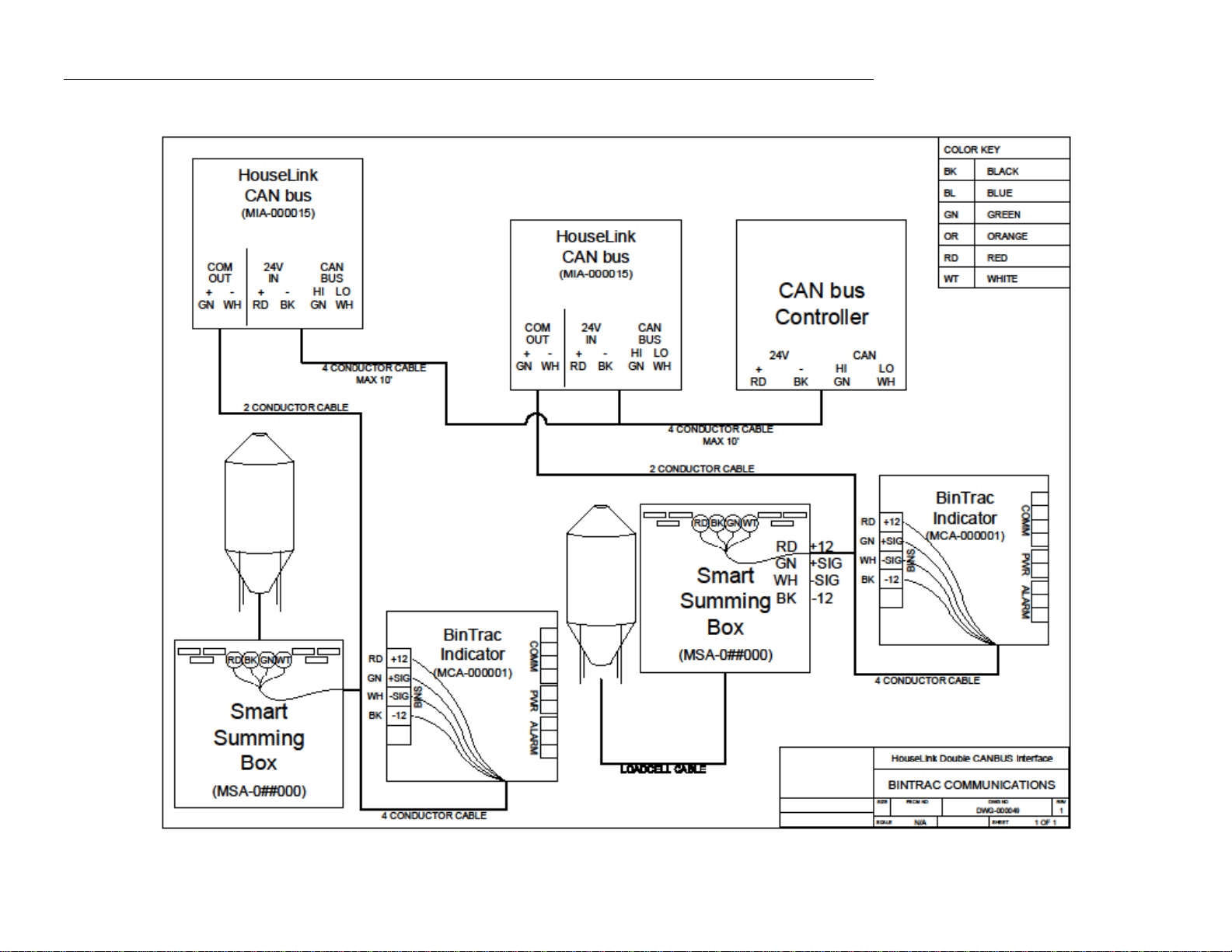
Wiring Diagram .......................................................................................................................................................................9
is a registered trademark of HerdStar, LLC.
Copyright © 2021 HerdStar, LLC. All rights reserved.
Printed in the USA

Installation and Operation Manual
HL-10C Installation Manual Rev 2.0 3Part Number MAN-000015
Description
The HouseLink HL-10C provides a CAN bus interface to the CAN bus controller.
The HouseLink HL-10C is designed to be used with the BinTrac Bin Weighing system. One HouseLink HL-10C can be
connected to one BinTrac indicator and can connect with a maximum of four bins.
Installation
1. The HouseLink HL-10C should be mounted no more than 10 feet from the CAN bus controller.
2. Using a two-conductor cable (ordered separately), connect the GREEN wire from the Smart Summing Box to the
+COM terminal in the HouseLink HL-10C and the White wire from the Smart Summing Box to the -COM terminal
in the HouseLink HL-10C.
3. Connect the HouseLink HL-10C to the CAN bus controller by connecting the CAN (HI) to the CAN (HI) terminal
and the CAN (LO) to CAN (LO) terminal of the CAN bus controller.
4. Finally, connect the 24V (+) from the HouseLink HL-10C to the 24V (+) of the CAN bus controller and the 24V (-)
from the HouseLink HL-10C to the 24V (-) of the CAN bus controller.
Table 1
HL-10C Interface
BinTrac Indicator
(BINS Port)
+COM (OUT)
+ SIG (GREEN wire)
-COM (OUT)
- SIG (WHITE wire)
HL-10C Interface
CAN Bus Controller
CAN (HI)
CAN (HI)
CAN (LO)
CAN (LO)
24V (+)
24V (+)
24V (-)
24V (-)
Figure 1
Installation and Operation Manual
HL-10C Installation Manual Rev 2.0 4Part Number MAN-000015
5. The unit has an 8-position dip switch that needs to be set up for configuration. Switches 1, 7, and 8 are set to ON
from the factory. See Table 2 for dip switch identification.
DIP 1
Lower bit of 0x40 offset CANopen device address. This DIP is set if the CANopen
address should be 0x40 + 0x01
DIP 2
Upper bit of 0x40 offset CANopen device address. This DIP is set if the CANopen
address should be 0x40 + 0x02
DIP 3
Unused
DIP 4
Unused
DIP 5
Unused
DIP 6
LB/KG Units setting. This DIP is set if the BinTrac is configured using kg units.
DIP 7
Use CANopen setting. This DIP is set if the Can bus controller should use the
CANopen protocol. Otherwise it uses the old (CAN Classic) communications routine.
DIP 8
120 Ohm Resistor. This DIP is set if the 120 Ohm termination resistor should be
applied to the CAN bus line.
BinTrac Indicator Setup
The BinTrac Indicator must be set up for peripheral devices. Access the SETUP menu on the BinTrac Indicator by
pressing and holding the BIN key for until SETUP is displayed on the screen, then release BIN key. With SETUP
displayed, press the BIN key until BIN D is selected. Use the UP/DOWN arrows to enable peripheral devices (BIN D LED
is solid ON).
The Bin LEDs indicate configuration options as being enabled (solid on) or disabled (flashing).
Bin A –Configures BinTrac Monitor as a Remote Display.
Bin B –Enable ASCII Serial Communications Command Set
Bin C –Enable Weight Broadcast.
Bin D –Enable communications to peripheral devices.
This must be enabled when BinTrac Indicator is connected to the HouseLink HL-10C.
LED Operation
CAN Bus Status LED:
SLOW FLASH –This indicates the unit is communicating and operating normally.
STEADY ON –This indicates the unit is not communicating but has power.
NO LIGHT –The unit doesn’t have an adequate power source
BinTrac Status LED:
SLOW FLASH –This indicates the unit is communicating and operating normally.
FAST FLASH –This indicates the unit is in TEST mode.
STEADY ON –This indicates the unit is not communicating but has power.
NO LIGHT –The unit doesn’t have an adequate power source
Table 2

Installation and Operation Manual
HL-10C Installation Manual Rev 2.0 5Part Number MAN-000015
Testing and Calibration
Reset/Test button:
Once the unit is wired up properly, the unit can be put into one of five test modes. These modes are useful when setting
up and testing with the CAN bus controller.
Test 1 –Press the Reset/Test button on the board once and the unit will output 0% full scale weight.
Test 2 –Press the Reset/Test button on the board twice and the unit will output 25% full scale weight.
Test 3 –Press the Reset/Test button on the board three times and the unit will output 50% full scale weight.
Test 4 –Press the Reset/Test button on the board four times and the unit will output 75% full scale weight.
Test 5 –Press the Reset/Test button on the board five times and the unit will output 100% full scale weight.
Pressing the test button a sixth time will return the unit to normal operation. If the unit is left in test mode, it will
automatically return to normal operation after five minutes.
CAN Open Setup
Make sure the CAN protocol is set to CANopen.
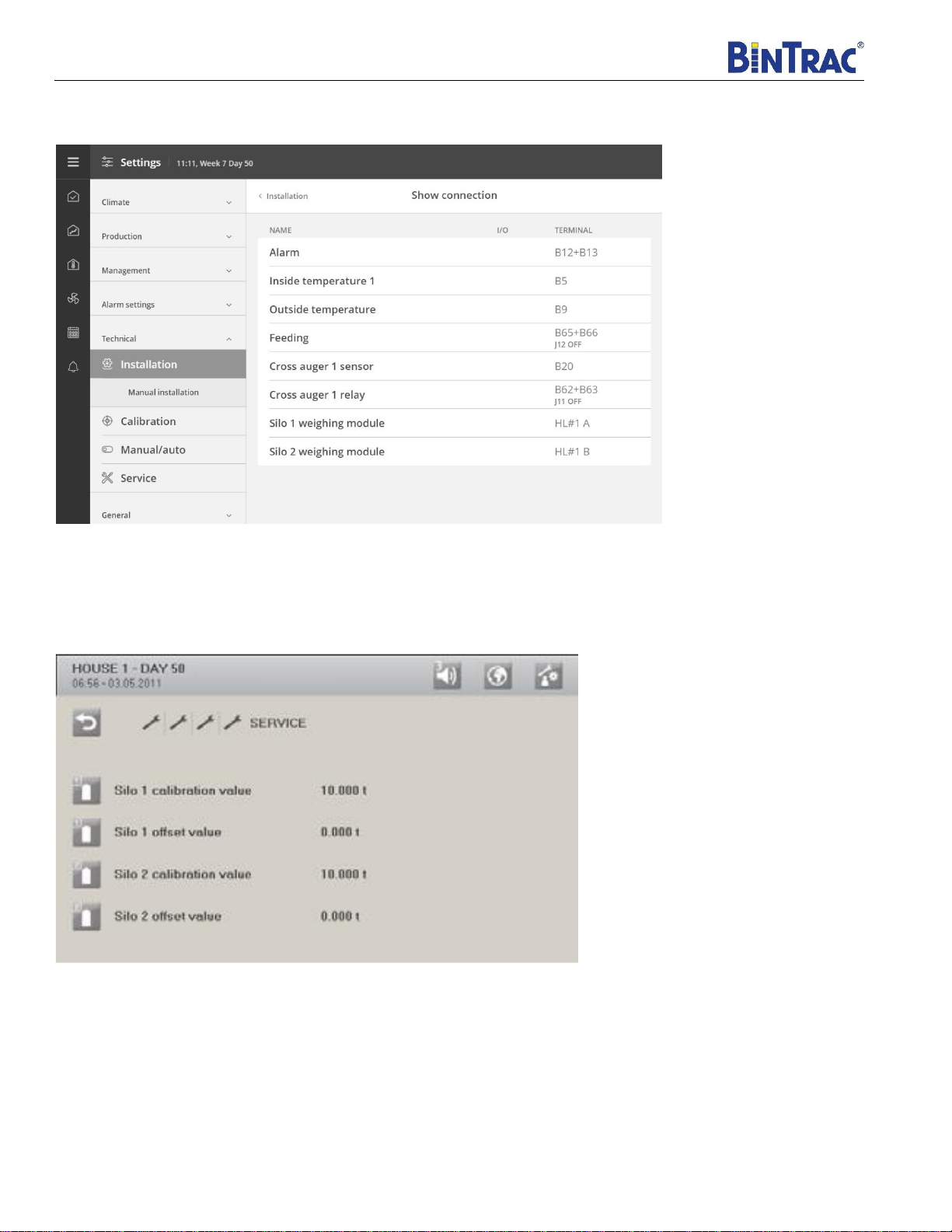
| Technical | Installation | Manual installation | CAN protocol

Installation and Operation Manual
HL-10C Installation Manual Rev 2.0 6Part Number MAN-000015
Here you see the CAN bus address (CAN ID) and if it is connected. Utilize address 41 for bins 1-4 and address 42 for bins
5-8.
| Technical | Installation | Manual installation | Silo weighing boxes
Select the number of BinTrac bins enabled. The CAN controller supports up to 8 electronic silo weighers.
| Technical | Installation | Manual installation | Silo weighing boxes
Installation and Operation Manual
HL-10C Installation Manual Rev 2.0 7Part Number MAN-000015
For correct connection of silo load cells, see menu | Technical | Installation | Show connection
CAN Classic Setup
The following two settings must be configured when using properly on the CAN bus controller to allow for accurate weight
communication with the BinTrac system.
1. Set Calibration value to same value as total Load Cell Capacity setting in the BinTrac Indicator.
2. Set Offset value to “0”.
For complete installation and setup of your CAN bus controller, please consult your user manual.

Installation and Operation Manual
HL-10C Installation Manual Rev 2.0 8Part Number MAN-000015
Operational Specifications
CAN Bus version: Compatible with ISO 11898 STANDARDS
Operating Temperature Range: -40°C to +60°C (-40°F to +140°F)
Operating Voltage Range: 10.5 VDC to 27.0 VDC
Humidity: 5% to 95% (non-condensing)
Environmental Air: No corrosive gasses permitted
Enclosure Type: Non-Sealed
Wiring Type: Screw terminal blocks
Installation and Operation Manual
HL-10C Installation Manual Rev 2.0 Part Number MAN-000015
Wiring Diagram
Other manuals for BinTrac HouseLink HL-10C
1
Table of contents
Other herdstar Recording Equipment manuals


