D&H SH05A Series User manual
Doehler & Haass
Sound module
SH05A SH10A

2Fahrzeug-/Funktionsdecoder ab Firmware-Version 1.11
2Contents
1 Introduction ............................................................................................................................................ 3
2 Safety instructions ................................................................................................................................. 4
3 Warranty ................................................................................................................................................. 4
4 Support and help.................................................................................................................................... 4
5 Soundmodul SH05A, SH10A ................................................................................................................. 5
5.1 Functions.................................................................................................................................................. 8
6 Installing the sound module ................................................................................................................. 9
6.1 Preparation ............................................................................................................................................... 9
6.2 Check after installation ............................................................................................................................. 9
6.3 Installation .............................................................................................................................................. 10
7 System format SUSI ............................................................................................................................ 12
7.1 Functions................................................................................................................................................ 12
7.2 Setting options ....................................................................................................................................... 12
7.3 List of supported CV or supported parameters ...................................................................................... 13
7.4 Operation................................................................................................................................................ 19

3
Fahrzeug-/Funktionsdecoder ab Firmware-Version 1.11 3
Sound module from firmware version 1.14
1 Introduction
The sound modules SH05A and SH10A are operated at the SUSI interface of a compatible car decoder. It can be used for
all data formats supported by the vehicle decoder.
Our SUSI sound modules can be electrically connected to all decoders with SUSI interface. Whether 3.3 Volt or 5 Volt
signals are used for the data and clock line is irrelevant. However, please note the maximum supply voltage of 30 Volt!
An operation on AC systems with change-over pulse is not permitted!
The change-over pulse leads to the destruction of the SUSI sound module!
Our SUSI sound modules must therefore not be installed in models which are also operated with analog AC voltage.
Our SUSI sound modules are not simplified products. In principle all sound functions are supported, which a sound decoder
would also support. There are only some minor restrictions. Other SUSI sound modules available on the market usually
have a clearly limited sound generation, which is not comparable with sound decoders at all. To make this possible, our
SUSI sound modules require a permanent supply of all data required for operation via the SUSI interface.
Unfortunately not all decoders on the market output such a signal at their SUSI interface. We can therefore not guarantee
an error-free function, if you connect the SUSI sound module to a decoder of the competitors. If you are unsure, please
contact us.

4Fahrzeug-/Funktionsdecoder ab Firmware-Version 1.11
4Sound module from firmware version 1.14
2 Safety instructions
This product is not suitable for children under 14 years.
It might be swallowed by children under 3 years!
An improper use involves a risk of injury due to sharp edges and points.
3 Warranty
The functioning of every sound module is fully tested before delivery. Should nevertheless a failure occur, please contact
the dealer where you purchased the sound module or directly the producer (Doehler & Haass enterprises). The warranty
period is two years from the data of purchase.
4 Support und help
In case you have any problems or questions please contact us by email technik@doehler-haass.de
Usually you will get an answer within a few days.

5
Fahrzeug-/Funktionsdecoder ab Firmware-Version 1.11 5
Sound module from firmware version 1.14
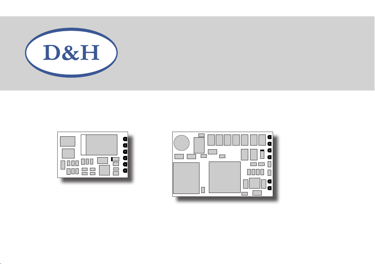
GND Ground
ZDAT SUSI data
ZCLK SUSI clock
VS Supply voltage
LS Speaker
AUX1, AUX2 Unamplified additional function 1, 2
maximum load capacity each 20 mA
+3,3 V Electronic supply voltage
(not for the user!)
maximum load capacity 100 mA
res. Please do not connect anything!
The “VS” connection of the sound module must be connected
to the “ZVS” connection of the decoder, if the decoder has
one. If not, use the “VS” connection of the decoder.
As in case the unamplified function outputs AUX1 and AUX2
(logic level 0 V - 3.3 V, max. 20 mA) cannot switch greater loads,
switching amplifiers (MOSFET, bipolar transistors or the like)
must be provided for consumers, which either require a higher
supply voltage (> 3.3 V) or a higher current (> 20 mA).
5 Sound module
SH05A / SH10A
SH05A
6Fahrzeug-/Funktionsdecoder ab Firmware-Version 1.11
6Sound module from firmware version 1.14
GND Ground
ZDAT SUSI data
ZCLK SUSI clock
VS Supply voltage
LS Speaker
AUX1, AUX2 Unamplified additional function 1, 2
maximum load capacity each 20 mA
+3,3 V Electronic supply voltage
(not for the user!)
maximum load capacity 100 mA
res. Please do not connect anything!
The “VS” connection of the sound module must be connected
to the “ZVS” connection of the decoder, if the decoder has
one. If not, use the “VS” connection of the decoder.
As in case the unamplified function outputs AUX1 and AUX2
(logic level 0 V - 3.3 V, max. 20 mA) cannot switch greater loads,
switching amplifiers (MOSFET, bipolar transistors or the like)
must be provided for consumers, which either require a higher
supply voltage (> 3.3 V) or a higher current (> 20 mA).
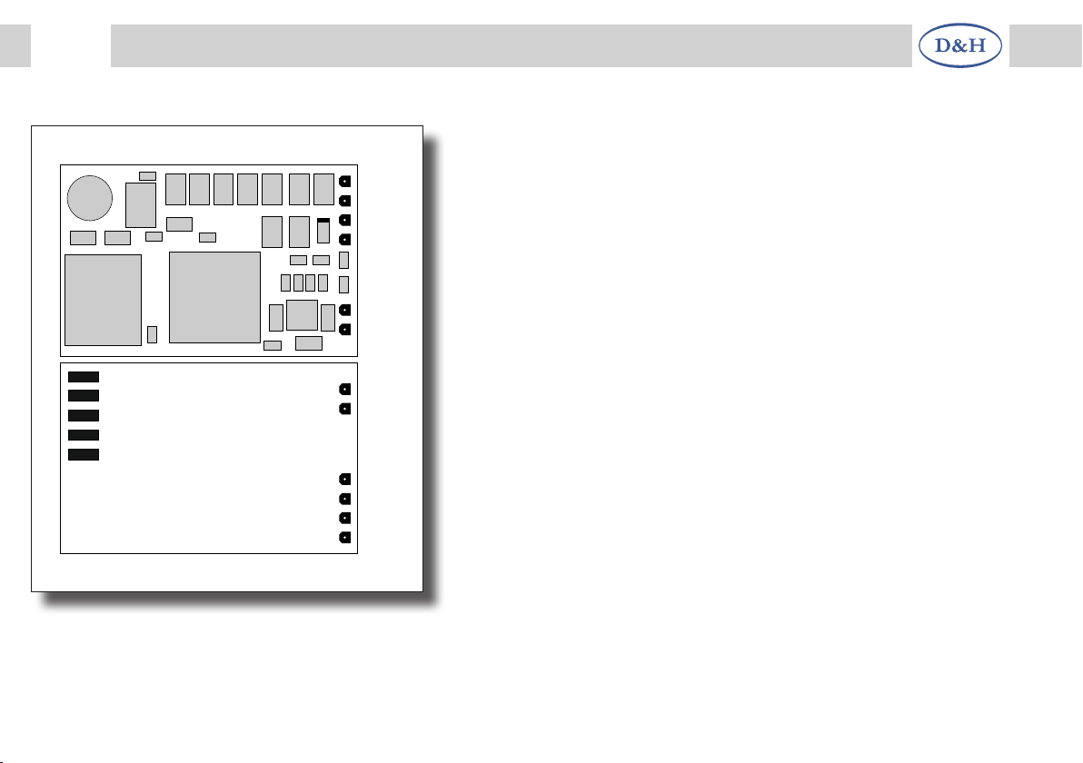
AUX2
AUX1
GND
+3,3 V
res.
ZDAT
ZCLK
LS
GND
VS
LS
SH10A

7
Fahrzeug-/Funktionsdecoder ab Firmware-Version 1.11 7
Sound module from firmware version 1.14
As in case the unamplified function outputs AUX1 and AUX2 (logic level 0 V - 3.3 V, max. 20 mA) cannot switch greater
loads, switching amplifiers (MOSFET, bipolar transistors or the like) must be provided for consumers, which either require
a higher supply voltage (> 3.3 V) or a higher current (> 20 mA).
Specifications SH05A SH10A
Dimensions [mm]
Sampling rate
Resolution
Independent sound channels
Memory size
Storage duration
Max. output power
Max. traction voltage
2 additional outputs (AUX1, AUX2)
14.3 x 9.3 x 2.9
22 kHz
16 Bits
8
128 Megabits
up to 760 s
1.6 W (8 Ω)
30 V
unamplified
20.0 x 12.0 x 1.9
22 kHz
16 Bits
8
128 Megabits
up to 760 s
2.6/1.6 W (4/8 Ω)
30 V
unamplified
Connecting options
Without connection wires
With connection cable for the SUSI interface
With connection wires
SH05A-0
SH05A-2
SH05A-3
SH10A-0
SH10A-2
SH10A-3

8Fahrzeug-/Funktionsdecoder ab Firmware-Version 1.11
8Sound module from firmware version 1.14
5.1 Functions
• Operation on all locomotive decoders with standard SUSI interface
• Original vehicle specific steam, diesel and electric locomotive sound projects (no „standard sounds“)
• Realistic steam driving noise with wheel synchronous and overlapping exhaust strokes, speed dependent pitch and
independent boiling noise
• Realistic diesel hydraulic driving noise with speed dependent pitch, variable idle speed and independent acceleration
stages, turbocharger and dynamic brake
• Realistic diesel mechanical driving noise with several gears, idle speed, several driving and acceleration stages and
possible shifting noise
• Realistic electrical driving noise with traction motor and traction motor fan as well as upgrade noises (pantograph,
main switch, etc.), switching mechanism noise and dynamic brake
• Bell, horn, whistle, closing doors, etc. (depending on sound project) can be triggered separately at any time
• All sound sequences are freely configurable (“Function Mapping“) and can be triggered randomly
• Speaker terminal protected against short circuit and overload
• Low heat generation through the use of the latest technologies
• Reset function
• Updateability of the firmware via SUSI interface using a programmer
• Loadability of sound projects via SUSI interface using a programmer
The update or loading is possible in the installed state of the sound module. The vehicle must be opened and the sound
module connected to the programmer via the SUSI interface. The software, firmware and sound project download can be
obtained from the Internet and is free of charge.

9
Fahrzeug-/Funktionsdecoder ab Firmware-Version 1.11 9
Sound module from firmware version 1.14
6 Installing the sound module
6.1 Preparation
Before installation, the locomotive must be checked for perfect electrical and mechanical condition. Defects or soiling must
be removed before installation. Basically the instructions of the locomotive manufacturer must be observed.
Before installing the sound module, the locomotive must also be checked for proper function in digital mode. With new
locomotives it is recommended to run the locomotive in each direction of travel for half an hour.
Furthermore all existing capacitors, especially at the connections for the light and the motor, have to be removed.
We recommend using double-sided adhesive tape to fix the sound module.
With sound modules, always solder the speaker first.
Carry out all soldering work in a de-energized state.
Avoid test drives with stripped unsoldered cable ends.
6.2 Check after installation
The first test should first be carried out in programming mode (e.g. by reading the manufacturer‘s code). If there is no
proper feedback to the central unit (“Error“), please check the assignment of the connections again.

10 Fahrzeug-/Funktionsdecoder ab Firmware-Version 1.11
10 Sound module from firmware version 1.14
6.3 Installation
There are three variants for connecting the sound module:
1 If your locomotive decoder has a SUSI standard socket, you should use the sound module SH05A-2 or SH10A-2. It
has the necessary connection cable for this socket. You can easily plug the connection cable of the sound module into
the interface.
2 If your locomotive decoder has SUSI soldering connections, the sound module must be wired individually. You should
use the sound module with the connecting leads for this purpose (SH05A-3 or SH10A-3).
3 The sound module SH05A-0 or SH10A-0 should only be used by experienced model railroaders, because here the
connecting wires have to be soldered directly onto the sound module.
Connect the wires of the sound module according to the following scheme:
black wire ....................... Ground (GND)
grey wire ......................... SUSI data (ZDAT)
blue wire ......................... SUSI clock (ZCLK)
red wire .......................... Supply voltage (ZVS)
brown wires .................... Speaker
The “VS” connection of the sound module must be connected to the “ZVS” connection of the decoder, if the decoder has
one. If not, use the “VS” connection of the decoder.

11
Fahrzeug-/Funktionsdecoder ab Firmware-Version 1.11 11
Sound module from firmware version 1.14
Function outputs:
The function outputs AUX1, AUX2 are located on the bottom of the sound module and must be connected to the switching
amplifiers with extra wires.
SH10A
GND
ZDAT
ZCLK
VS
Locomotive decoder with SUSI
LS
LS

12 Fahrzeug-/Funktionsdecoder ab Firmware-Version 1.11
12 Sound module from firmware version 1.14
7 System format SUSI
7.1 Functions
Speed steps ...................................127
Front light/rear light ....................... yes
Additional functions .........................28
Main track programming ............... yes
7.2 Setting options
The properties of the sound module for operation can be changed as often as desired by programming the “Configuration
Variables” (CV) or the parameters (par). Please take the programming informations out of the instructions of your
programming device.
The sound module always occupies the CV ranges 1 and 2, so an additional SUSI module must be set to CV range 3
(CV897/par897 = 3). The SH05A or SH10A sound module can remain connected for this purpose, as it does not react to
readout or programming commands from CV897/par897. This avoids the cumbersome and difficult to understand “CV
banking” procedure (see SUSI specification version 3.10 for more information).
Hint:
If different speed levels are programmed in the locomotive decoder in DCC mode than in the driving unit, malfunctions may
occur. These also affect connected sound modules. Please also note the instructions for your digital system.

13
Fahrzeug-/Funktionsdecoder ab Firmware-Version 1.11 13
Sound module from firmware version 1.14
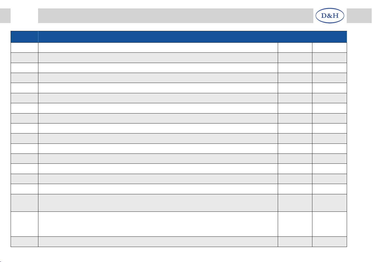
7.3 List of supported CVs and supported parameters
CV/par Name and definition Range Standard
900 Manufacturer identification (read only)
97 = Doehler & Haass (Decoder reset with “8“ or “101“)
901 Decoder number (read only)
SH05A = 50, SH10A = 100
902 Version number (read only)
903 Date (read only)
904 Revision number (read only)
905 Date (read only)
908 Function mapping AUX1
0 = deactivated, 1 ... 28 = F1 ... F28, 29 = F0 (light),
30 = driving sound, 31 = secondary driving sound, 32 = gear sound,
33 = brake sound, 34 ... 46 = sound flow 4 ... 16, values greater 46 = deactivated
Sound flow 3 is not available for technical reasons!
0-255 0
909 Function mapping AUX2 (as CV908) 0-255 0
911 Function mapping driving sound
0 = deactivated, 1 … 28 = F1 … F28, 29 = F0 (light)
Traction motor at electric locomotives, chuffs at steam locomotives, etc.
0-29 1
912 Function mapping secondary driving sound (as CV911)
Traction motor fan at electric locomotives, boiling sound at steam locomotives, etc.
0-29 1
913 Function mapping gear sound (as CV911) 0-29 0
914 Function mapping brake sound (as CV911) 0-29 7
14 Fahrzeug-/Funktionsdecoder ab Firmware-Version 1.11
14 Sound module from firmware version 1.14
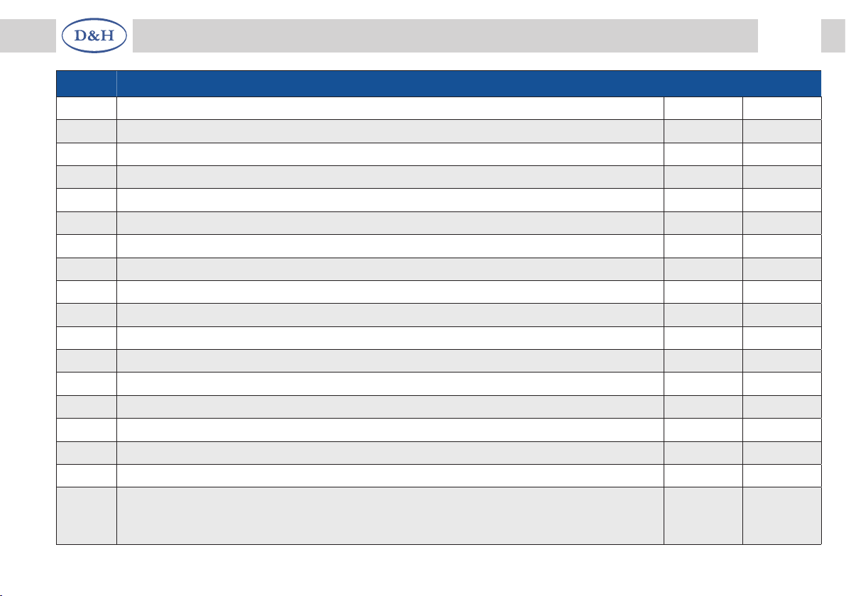
CV/par Name and definition Range Standard
915 Function mapping sound flow 3 (as CV911) 0-29 2
916 Function mapping sound flow 4 (as CV911) 0-29 3
917 Function mapping sound flow 5 (as CV911) 0-29 4
918 Function mapping sound flow 6 (as CV911) 0-29 5
919 Function mapping sound flow 7 (as CV911) 0-29 6
920 Function mapping sound flow 8 (as CV911) 0-29 9
921 Function mapping sound flow 9 (as CV911) 0-29 10
922 Function mapping sound flow 10 (as CV911) 0-29 11
923 Function mapping sound flow 11 (as CV911) 0-29 12
924 Function mapping sound flow 12 (as CV911) 0-29 13
925 Function mapping sound flow 13 (as CV911) 0-29 14
926 Function mapping sound flow 14 (as CV911) 0-29 15
927 Function mapping sound flow 15 (as CV911) 0-29 16
928 Function mapping sound flow 16 (as CV911) 0-29 17
929 Function mapping fade-out effect (as CV911) 0-29 8
930 Total volume
0 … 255 = 0% … 100%
0-255 64
931 Volume driving sound
0 … 128 … 255 = 0% … 100% …200%
Value higher 100% can lead to overload!
0-255 128
932 Volume secondary driving sound (as CV931) 0-255 128
15
Fahrzeug-/Funktionsdecoder ab Firmware-Version 1.11 15
Sound module from firmware version 1.14
CV/par Name and definition Range Standard
933 Volume gear sound (as CV931) 0-255 128
934 Volume brake sound (as CV931) 0-255 128
935 Volume sound flow 3 (as CV931) 0-255 128
936 Volume sound flow 4 (as CV931) 0-255 128
937 Volume sound flow 5 (as CV931) 0-255 128
938 Volume sound flow 6 (as CV931) 0-255 128
939 Volume sound flow 7 (as CV931) 0-255 128
940 Volume sound flow 8 (as CV931) 0-255 128
941 Volume sound flow 9 (as CV931) 0-255 128
942 Volume sound flow 10 (as CV931) 0-255 128
943 Volume sound flow 11 (as CV931) 0-255 128
944 Volume sound flow 12 (as CV931) 0-255 128
945 Volume sound flow 13 (as CV931) 0-255 128
946 Volume sound flow 14 (as CV931) 0-255 128
947 Volume sound flow 15 (as CV931) 0-255 128
948 Volume sound flow 16 (as CV931) 0-255 128
949 Volume fade-out effect (as CV930) 0-255 0
950 Coasting delay time
The value corresponds to the time in 100 ms steps until the compulsory change
from driving sound to coasting. 0 = deactivated
0-255 0

16 Fahrzeug-/Funktionsdecoder ab Firmware-Version 1.11
16 Sound module from firmware version 1.14
CV/par Name and definition Range Standard
951 Acceleration time
The value corresponds to the time in seconds from standstill to maximum speed
0-255 3
952 Braking time
The value corresponds to the time in seconds from the maximum speed
until stopped
0-255 3
953 Chuffs at speed step 1
The value corresponds to the time in 64 ms steps between the chuffs
at speed step 1
0-255 120
954 Chuffs at higher speed steps
The value determines the time of reduction between the chuffs at
higher speed steps
0-255 20
955 Brake squeal at minimal speed step
The minimum speed step that must be reached, to make brake squeal possible
0-127 20
956 Brake squeal at initial speed step
The speed step at which brake squeal begins when the vehicle stops
0-127 13
957 Secondary driving sound modulation
The value determines how strongly the speed level influences the pitch.
0 = deactivated
0-255 0
958 Driving sound modulation (as CV957) 0-255 11
959 Timer for fade-out effect
The value corresponds to the time in seconds from the adjusted
total volume to silence
0-255 8
17
Fahrzeug-/Funktionsdecoder ab Firmware-Version 1.11 17
Sound module from firmware version 1.14
CV/par Name and definition Range Standard
960 Write protection Flash-ROM
Must be “0“ for sound operation (is operated during the loading process)
0, 1 0
961 Threshold value ZVS
The value corresponds to about the supply voltage in volt. At that voltage it will be
changed to the energy saving mode (small values induces resetting the sound mo-
dule and great values cause a “stuttering“ sound).
0-14 7
962 Chuffs at speed step 127
The value corresponds to the minimum time in 1 ms steps between the chuffs
at speed step 127, which must not be undercut
0-255 0
964 Brake squeal at final speed step
The speed step, where the brake squeal changes into the final sequence of the
sound flow (actual end at speed step 0 at the latest).
0-127 6
965 Brake squeal at deceleration time
The value corresponds to the time in 8 ms steps, which may pass by between
two speed step reductions, in order that brake squeal is still possible.
0-255 3
966 Brake squeal at minimum delay
The value corresponds to the number of speed steps, which must run through
within the deceleration time at least, in order that brake squeal is still possible.
0-127 0
967 Random sounds
Bit Function Value
0........Random sounds allowed while standing ....................................1
1........Random sounds allowed while running .....................................2
2........Currently without function
0-7 3
968 Volume dynamic sound (as CV931) 0-255 128
969 Volume turbo sound (as CV931) 0-255 128

18 Fahrzeug-/Funktionsdecoder ab Firmware-Version 1.11
18 Sound module from firmware version 1.14
CV/par Name and definition Range Standard
970 Modulation dynamic brake (as CV957) 0-255 0
971 Modulation dynamic drive (as CV957) 0-255 0
972 Modulation turbo sound proportional part (as CV957) 0-255 0
973 Modulation turbo sound integral part (as CV957) 0-255 0
974 Function mapping volume reduction (as CV911)
With every keystroke (on/off) the total volume will be permanently reduced
0-29 0
975 Function mapping volume enhancement (as CV911)
With every keystroke (on/off) the total volume will be permanently enhanced
0-29 0
976 Function mapping brake squeal deactivation (as CV911)
If the corresponding function key is pushed, no brake squeal will be
represented, even if the conditions should actually be fulfilled for it
0-29 0
977 Function mapping forced coasting (as CV911)
If the corresponding function key is pushed, the driving sound remains
coasting even during acceleration
0-29 0
978 Function assignment automatic idle (as CV911)
When the corresponding function key is pressed,
the automatic idling after the time period from CV350 has elapsed.
If no function key is assigned, the automatic idle is always effective.
0-29 0
979 Function assignment forced acceleratio (as CV911)
When the corresponding function key is pressed,
the driving noise even during a deceleration in acceleration.
0-29 0
All programmable CVs can be changed during operation (POM / “Programming On The Main“ / main track programming).
The given default values can be overwritten depending on the sound project!

19
Fahrzeug-/Funktionsdecoder ab Firmware-Version 1.11 19
Sound module from firmware version 1.14
7.4 Operation
Put the locomotive on the programming track and read out the manufacturer identification of the sound module (CV900/
par900). The default value should be 97. Program the desired locomotive address and start running the locomotive
keeping these setup values. After the first check you can vary the CV or parameters of the locomotive according to your
requirements.
In case your programming device indicates “Error“, please check again the correct wiring of the locomotive and pay
attention to the notices for connecting the programming track. Never put such a locomotive into operation!
Please take the mapping, which sound flow corresponds to which sound, from the instruction of the particular sound
project. Not all sound flows from 1 to 16 must contain sounds.
Starting delay:
The starting delay from speed level 0 to speed level 1 (CV63/par016) of the locomotive decoder should be set to a suitable
value. Unsuitable values will result in the starting of the locomotive not matching the noise level. The exact value depends
on the individual sound data.
Hint:
The acceleration time (CV03/par011) and the braking time (CV04/par012) of the locomotive decoder should be set to at
least value 8. Times that are set too low will cause some sound sequences to be skipped and cannot be played back! If
necessary the values of CV/par951 and CV/par952 can be increased step by step for fine tuning.

20 Notes
This manual suits for next models
7
Table of contents


