Herman Miller Echo 2G System User manual

Echo 2G System User Manual
HMS Space Utilization Service
HERMAN MILLER INC
page 1 of 9
Echo 2G System User Manual Copyright, 2010, Herman Miller Inc.
Revision: 1.1
1. System Overview
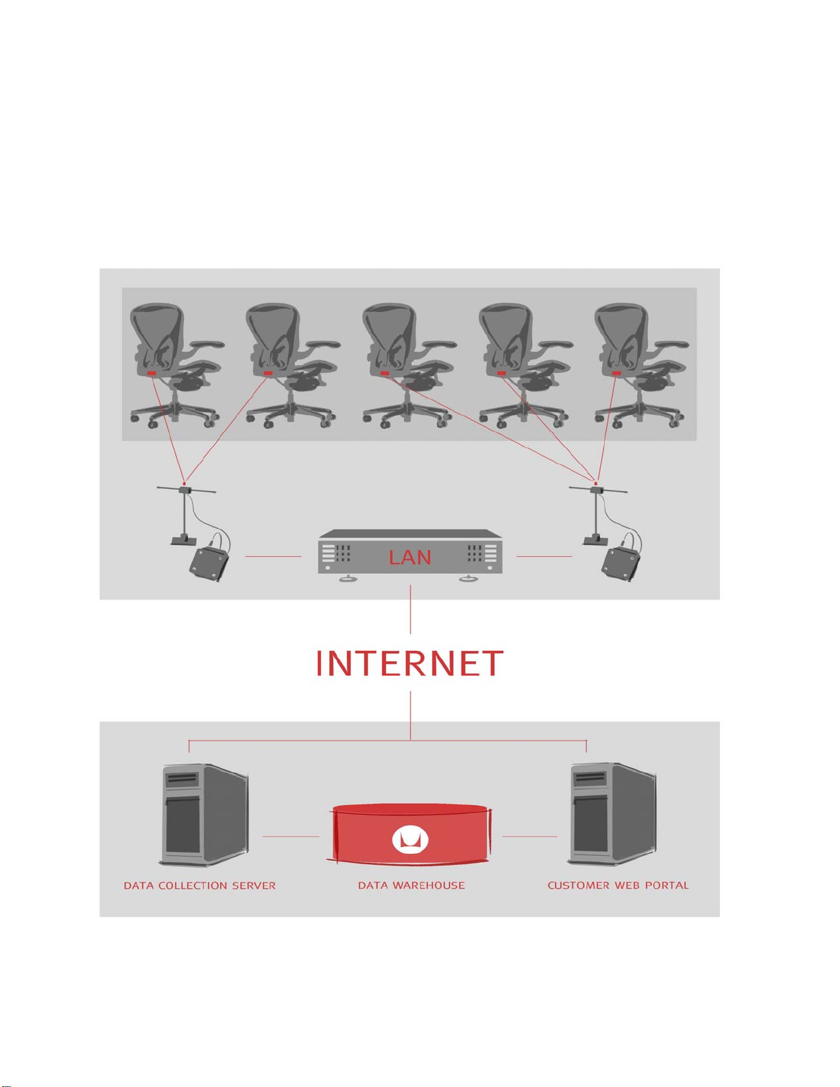
Echo 2G is a redeployable and scalable multi-tier sensing system that is installed at a customer facility for a period
of 3 to 5 weeks to capture space utilization rates. The system employs three technology tiers to capture, aggregate,
and transmit workplace utilization data for analysis and trend reporting. Figure 1 Echo 2G System Diagram
illustrates the relationship between those tiers.
Figure 1 Echo 2G System Diagram
HERMAN MILLER INC
page 2 of 9
Echo 2G System User Manual Copyright, 2010, Herman Miller Inc.
Revision: 1.1
Furniture Tier
This tier determines occupancy by sensing movement of a chair in the customer facility. Motion data is
transmitted wirelessly to receivers.
Room Tier
This tier aggregates motion data from the furniture tier. The data is periodically transmitted to Herman Miller over
the Internet via either: 1) the customer LAN or 2) a wireless network comprising a 900 MHz wireless backhaul
network, a wireless gateway and a cellular router.
Analysis Tier
This tier stores all customer data on a secure server at Herman Miller for value-added analysis and reporting.
2. System Deployment and Operation Overview
The Echo 2G system is designed to be easily deployed and operated at customer facilities. Receivers are first
deployed across the customer study site, and then motes are deployed to predefined spaces in the customer
study area. Motes communicate occupancy data to receivers, receivers communicate occupancy data to the
Herman Miller DCS over the Internet, and the DCS stores occcupancy data in a database, where it is later used
to generate customer reports.
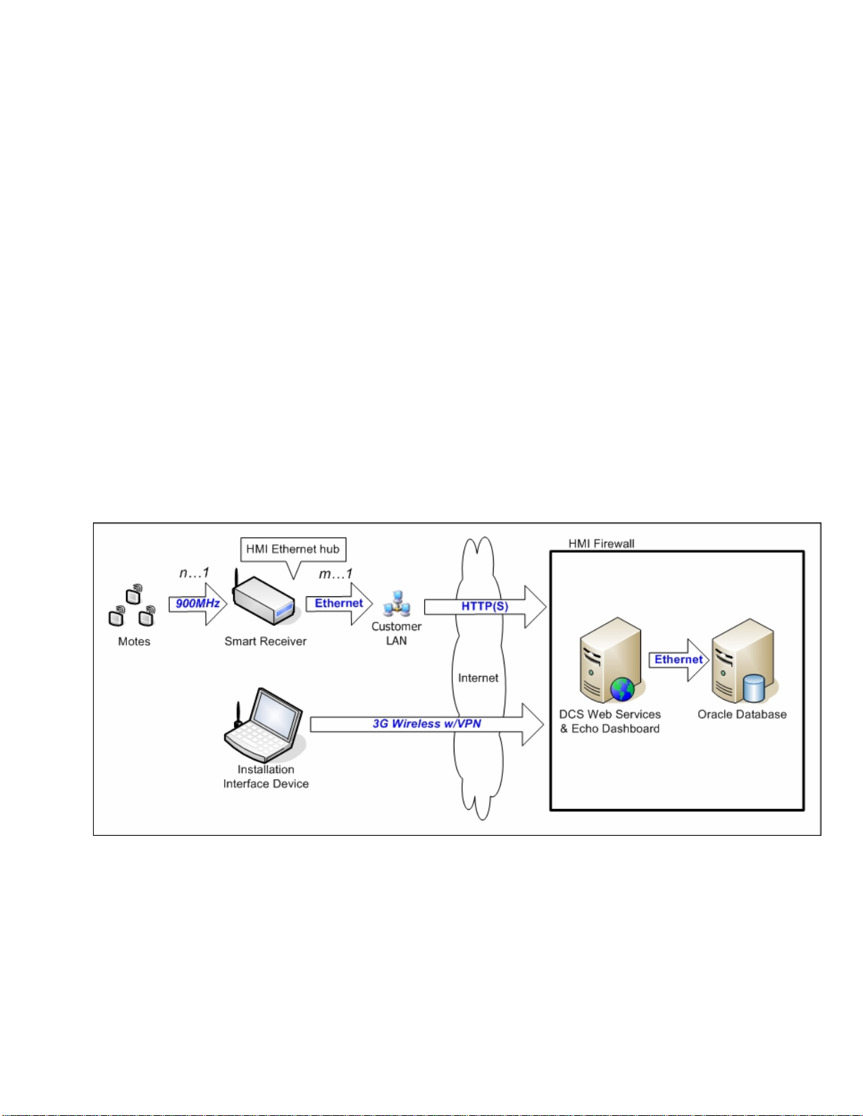
The communication protocols between components are illustrated in Figure 2 Data flow diagram with protocols.
Figure 2 Data flow diagram with protocols
Two types of messages are transmitted from receivers to the DCS (data collection server). First, raw occupancy
data is encapsulated in an HTTP or HTTPS POST request, which contains binary data from linked motes.
Second, a short heartbeat packet containing operational metrics is transmitted every 10 minutes; this heartbeat
packet is used to monitor system status and connectivity. The DCS acknowledges all messages. These
acknowledgements may include receiver commands.
HERMAN MILLER INC
page 3 of 9
Echo 2G System User Manual Copyright, 2010, Herman Miller Inc.
Revision: 1.1

3.1. RF Environment
The wireless motes communicate with receivers in the 902-928MHz band, so will not interfere with WiFi,
Bluetooth, or Zigbee wireless networks, all of which operate in the 2.4GHz band.
3.2. Power and Data Lines
All receivers require power and data connections. They must be placed within wireless range of a subset of
motes, where the wireless range between a mote and a receiver is approximately 100 feet indoors. A receiver is
capable of linking with over 300 motes, but on average, will link with about 30 motes. To achieve redundant
mote coverage, a deployment of 600 motes requires approximately 30 receivers.
3.3. IP Addresses
To simplify installation, receivers use dynamic IP addresses. These IP addresses are assigned by the DHCP
server on the customer Local Area Network (LAN) along with a subnet mask and default gateway.
3.4. Internet Access
Receivers send data via the Internet HTTPS. Heartbeat messages are transmitted every 10 minutes. Occupancy
data is transmitted less frequently. If required, receivers may be configured to use a web proxy server.
3.5. Internet Services
Receivers use several common Internet services to communicate the space utilization information to the DCS,
including DNS to resolve the hostname of the DCS.
3.6. Deployment Laptop
A wireless laptop is used to assign individual motes to predefined spaces. A barcode scanner is attached to the
USB port of this laptop. This scanner functions as a secondary keyboard.
3. Detailed Process and Deployment Steps
Conducting a Space Utilization Study using the Echo 2G system is a four-step process.
Step One: Gather Information
The customer facility management team provides Herman Miller with information required to conduct the study.
This information includes study objectives, location, desired dates, number of motes required, desired reports, a
floor plan, and a spreadsheet identifying all workspaces to be monitored during the course of the study. For each
of these spaces, the spreadsheet should also contain any optional attributes that may be required to generate
desired reports.
In this step, Herman Miller obtains the necessary customer IT approvals if the Echo 2G system is to be
connected to the customer LAN.
Step Two: Setup
The required equipment is sent to the customer study site in one or more shipping containers. The key pieces of
equipment are the motes and the receivers.
HERMAN MILLER INC
page 4 of 9
Echo 2G System User Manual Copyright, 2010, Herman Miller Inc.
Revision: 1.1

Important
Changes not expressly approved by Herman Miller, Inc. could void the user's authority to operate the
equipment.
Note: This equipment has been tested and found to comply with the limits for a Class B digital device,
pursuant to Part 15 of the FCC Rules. These limits are designed to provide reasonable protection against
harmful interference in a residential installation. This equipment generates, uses and can radiate radio
frequency energy and, if not installed and used in accordance with the instructions, may cause harmful
interference to radio communications. However, there is no guarantee that interference will not occur in a
particular installation. If this equipment does cause harmful interference to radio or television reception,
which can be determined by turning the equipment off and on, the user is encouraged to try to correct the
interference by one or more of the following measures:
- Reorient or relocate the receiving antenna.
- Increase the separation between the equipment and receiver.
- Connect the equipment into an output on a circuit different from that to which the receiver is connected.
- Consult the dealer or an experienced radio/TV technician for help.
This product complies with FCC OET Bulletin 65 radiation exposure limits set forth for an uncontrolled
environment.
Operation is subject to the following two conditions: (1) This device may not cause harmful interference. and
(2) this device must accept any interference received, including interference that may cause undesired
operation.
This Class B digital apparatus complies with Canadian ICES-003.
Cet appareil numériqué de la classe B est conformé à la norme NMB-003 du Canada.
Motes
Motes are small, battery-powered motion sensors that attach beneath chairs using
Velcro or zip ties. Each mote links with a single receiver and transmits wireless
occupancy data to that receiver. The mote transmitter operates in the 902-928 MHz
ISM band at 0.001 W with a 59% duty cycle per 100ms.
Receivers
Receivers collect occupancy data transmitted by the motes. A single
receiver will receive and acknowledge data from all motes linked to it. The
receiver transmitter operates in the 902-928 MHz ISM band at 0.001 W with
a 36% duty cycle per 100ms.
To ensure reliable reception of mote data, receivers should be deployed at
the customer site such that at least two receivers are within 100 feet of
every mote; this redundancy allows a mote to relink with the second receiver
if it loses its link with the first receiver. Note that 100 feet is a typical link
range between mote and receiver; actual link range may vary depending on
HERMAN MILLER INC
page 5 of 9
Echo 2G System User Manual Copyright, 2010, Herman Miller Inc.
Revision: 1.1

obstructions or radio interference.
The receiver uses a unique antenna connector. The receiver is to be used only with a ½ -wave center fed dipole
antenna with a gain of 2.2 dBi or less, such as the Antenna Factor ANT-916-CW-HWR-RPS.
Installation
During installation, receivers are deployed across the customer study site and motes are deployed to predefined
spaces in the customer study area.
I. Install Receivers
Deploy receivers to designated spaces to ensure adequate mote coverage.
•If there is only one network port, deploy a network switch for connecting the receiver to the customer
LAN
Note: this ensures that customers still have access to the LAN
•Deploy a multi-outlet power strip to supply power to the receiver and the optional network wwitch
Deploy Network Switches
Note: If there is only one network port, deploy a network switch for connecting the receiver to the customer
LAN
Step 1. Connect Network Switch to AC power via power adaptor
Step 2. Connect Network Switch to customer LAN port using CAT5 network cable
Step 3. Connect Receiver to Network switch using CAT5 network cable
Step 4. From main menu of Administrative User Interface under Deploy Menu, click on
Deploy Equipment
Step 5. From drop down list, select current Company (customer)
Step 6. From drop down list, select current Study
Step 7. From drop down list, select Deployment Type of Drop Down
Step 8. Repeat Step 8.1 through Step 8.8 for each Network Switch
Step 8.1 From drop down list, select current Building
Step 8.2 From drop down list, select current Floor
Step 8.3 From drop down list, select current Area
Step 8.4 From drop down list, select current Space
Step 8.5 Place cursor in the Device Barcode
Step 8.6 Scan barcode on Network Switch
Step 8.7 If you want to note comments either about the condition of the Network Switch or its
environment, type those comments in the Comments section
Step 8.8 Click Submit
Deploy Receivers
Note: Receivers must be configured for a study prior to deployment. Receivers must be deployed before
motes are deployed.
Step 1. Connect Receiver to Network switch using CAT5 network cable
Step 2. Connect Receiver to AC power via power adaptor
Step 3. Confirm that the Receiver LCD displays the following test results in sequence within
30 seconds: host <version>…ok
sbc <version>…ok
radio module <version>…ok
backhaul…ok
network…ok
HERMAN MILLER INC
page 6 of 9
Echo 2G System User Manual Copyright, 2010, Herman Miller Inc.
Revision: 1.1

DCS…ok
Step 4. From main menu of Administrative User Interface under Deploy Menu, click on
Deploy Equipment
Step 5. From drop down list, select current Company (customer)
Step 6. From drop down list, select current Study
Step 7. From drop down list, select Deployment Type of Drop Down
Step 8. Repeat Step 8.1 through Step 8.9 for each Receiver
Step 8.1 From drop down list, select current Building
Step 8.2 From drop down list, select current Floor
Step 8.3 From drop down list, select current Area
Step 8.4 From drop down list, select current Space
Step 8.5 Place cursor in the Device Barcode
Step 8.6 Scan barcode on Receiver
Step 8.7 If you want to note comments either about the condition of the Receiver or its
environment, type those comments in the Comments section
Step 8.8 Click Submit
Step 8.9 After clicking Submit, confirm that Confirmation box indicates Proceed within 5
seconds
Step 8.10 Hang/Place “Study in Progress, Do Not Remove” placard on Receiver
II. Install Motes
Deploy motes to designated spaces to monitor occupancy
Deploy Motes
Step 1. Press and hold Mote button for 3 seconds (a single beep tone will sound at 3
seconds) to power up Mote (exit Shutdown Mode)
Step 2. Confirm that Mote sounds 2 ascending beep tones to indicate power-up
Step 3. Confirm that Mote does NOT sound a 1-second Low Battery beep tone after 1
second
Step 4. From main menu of Administrative User Interface under Deploy Menu, click on
Deploy Equipment
Step 5. From drop down list, select current Company (customer)
Step 6. From drop down list, select current Study
Step 7. From drop down list, select Deployment Type of Drop Down
Step 8. Repeat Step 8.1 through Step 8.8 for each Mote
Step 8.1 From drop down list, select current Building
Step 8.2 From drop down list, select current Floor
Step 8.3 From drop down list, select current Area
Step 8.4 From drop down list, select current Space
Step 8.5 Place cursor in the Device Barcode
Step 8.6 Scan barcode on Mote
Step 8.7 If you want to note comments either about the condition of the Mote or its
environment, type those comments in the Comments section
Step 8.8 Mount Mote under front lip of task chair using Velcro, tie wrap or, if the Mote must
be attached to fabric, a basting gun
Step 8.9 Press and release Mote button within 0.5 second
Step 8.10 Confirm that Mote sounds single beep tone indicating it is powered on
Step 8.11 Confirm that within 3 seconds, the Mote sounds at least 3 additional beep tones,
indicating Received Signal Strength (RSS) of Receiver signal is acceptable.
IMPORTANT: If the Mote sounds 1-second Low Battery beep tone, replace
Mote battery with new battery or select a different Mote.
HERMAN MILLER INC
page 7 of 9
Echo 2G System User Manual Copyright, 2010, Herman Miller Inc.
Revision: 1.1

Step 8.12 Click Submit
Step 8.13 After clicking Submit, confirm the following:
Step 8.13.1 Confirmation box indicates Proceed within 5 seconds
Step 8.13.2 Deployment screen indicates that at least 2 Receivers provide acceptable RSS
Step Three: Monitor
Once all equipment has been installed, data will be transmitted to Herman Miller via the Internet for analysis. A
Herman Miller analyst will determine whether data is being collected properly, and may contact the customer to
assist in simple troubleshooting, e.g., to check whether a receiver’s AC power plug has become unplugged.
At the conclusion of a customer study, Herman Miller will analyze the collected occupancy data data and create
reports that present and interpret the findings.
Step Four: Remove
At the conclusion of a customer study, all equipment must be collected, repackaged, and returned to Herman
Miller. Customers are responsible for any lost equipment.
III. Remove Motes
Return motes to shipping kit.
Remove Motes
Step 1. Repeat Step 2 through Step 14 for each Mote
Step 2. Detach Mote from the underside of the front lip of the task chair.
Step 3. Press and hold Mote button for 3 seconds (a single beep tone will sound at 3
seconds) to power down Mote (enter Shutdown Mode)
Step 4. Confirm that Mote sounds 2 descending beep tones to indicate power-down
Step 5. From main menu of Administrative User Interface under Deploy Menu, click on
Deploy Equipment
Step 6. From drop down list, select Deployment Type of Drop Down
Step 7. From drop down list, set Building to Kit
Step 8. From drop down list, set Floor to Kit
Step 9. From drop down list, set Area to Kit
Step 10. From drop down list, set Space to Kit
Step 11. Place cursor in the Device Barcode
IMPORTANT: If the Deployment screen indicates that fewer than 2 Receivers
provide acceptable RSS, then the deployment does not have acceptable mote
coverage redundancy. Reposition or relocate one or more Receivers and
reassess Receiver RSS by pressing the Mote button again. Confirm that at least
2 Receivers provide acceptable RSS.
IMPORTANT: If the Mote sounds fewer than 3 beep tones, the RSS is too low
to support reliable communications. Once the identity of the linked Receiver is
known (see Step 8.13.2 below), this Receiver should be repositioned (placed
closer to the ceiling) and/or relocated (closer to the Mote), and the Receiver
RSS reassessed by pressing the Mote button again. Note that relocating the
Receiver may affect the RSS of other Motes.
HERMAN MILLER INC
page 8 of 9
Echo 2G System User Manual Copyright, 2010, Herman Miller Inc.
Revision: 1.1

Step 12. Scan barcode on Mote
Step 13. If you want to note comments either about the condition of the Mote or its
environment, type those comments in the Comments section
Step 14. Click Submit
IV. Remove Receivers
Return receivers to shipping kit.
If a multi-outlet power strip was deployed, unplug the receiver and optional network switch from the power
strip and return the power strip to the shipping kit.
Remove Network Switches
Step 1. Repeat Step 2 through Step 14 for each Network Switch
Step 2. Disconnect Network Switch from AC power
Step 3. Disconnect Network Switch from customer LAN port
Step 4. Disconnect Receiver from Network Switch
Step 5. From main menu of Administrative User Interface under Deploy Menu, click on
Deploy Equipment
Step 6. From drop down list, select Deployment Type of Drop Down
Step 7. From drop down list, set Building to Kit
Step 8. From drop down list, set Floor to Kit
Step 9. From drop down list, set Area to Kit
Step 10. From drop down list, set Space to Kit
Step 11. Place cursor in the Device Barcode
Step 12. Scan barcode on Network Switch
Step 13. If you want to note comments either about the condition of the Network Switch or its
environment, type those comments in the Comments section
Step 14. Click Submit
Remove Receivers
Step 1. Repeat Step 2 through Step 13 for each Receiver
Step 2. Disconnect Receiver from AC power
Step 3. Disconnect Receiver from customer LAN port
Step 4. From main menu of Administrative User Interface under Deploy Menu, click on
Deploy Equipment
Step 5. From drop down list, select Deployment Type of Drop Down
Step 6. From drop down list, set Building to Kit
Step 7. From drop down list, set Floor to Kit
Step 8. From drop down list, set Area to Kit
Step 9. From drop down list, set Space to Kit
Step 10. Place cursor in the Device Barcode
Step 11. Scan barcode on Receiver
Step 12. If you want to note comments either about the condition of the Receiver or its
environment, type those comments in the Comments section
Step 13. Click Submit
IMPORTANT: Remember to return multi-outlet power strip, AC power adaptors,
CAT5 cables and placards to kit.
HERMAN MILLER INC
page 9 of 9
Echo 2G System User Manual Copyright, 2010, Herman Miller Inc.
Revision: 1.1
Table of contents


