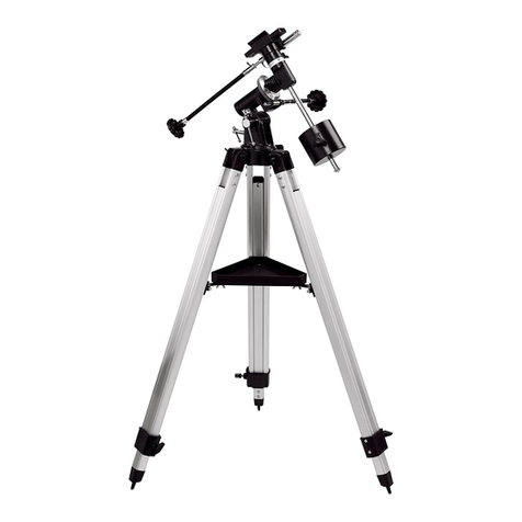
Orion SkyView Deluxe 9400 User manual

IN 097 Rev. A 0898
Providing Exceptional Consumer Optical Products Since 1975
Customer Support (800) 676-1343
E-mail: [email protected]
Corporate Offices (831) 763-7000
P.O. Box 1815, Santa Cruz, CA 95061
INSTRUCTION MANUAL
Orion®
SkyView™ Deluxe
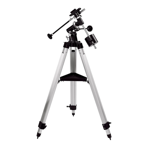
Equatorial Mount
#9400

2
Figure 1. SkyView Deluxe EQ Mount Parts Diagram
Tube ring mounting bolt
Declination
setting circle
Declination lock lever
Right ascension slow-
motion control
Counterweight shaft
Counterweight
Counterweight
lock knob
Retaining washer
and knob
Tripod leg attachment bolt
Accessory tray bracket
Accessory tray
Declination slow-
motion control
Right ascension lock lever
Right ascension
setting circle
Polar axis finder scope
Latitude adjustment knob
Latitude lock lever
Azimuth adjustment
knob
Tripod leg
Leg lock bolt
Rubber foot

3
1. PARTS LIST
Qty. Description
1 German-type equatorial mount
1 Polar axis finder scope
2 Slow-motion control cables
1 Counterweight
1 Counterweight shaft
3 Tripod legs
1 Tripod accessory tray
3 Accessory tray screws and wing nuts
2. ASSEMBLY
Carefully open all of the boxes in the shipping container.
Make sure all the parts listed in section 1 are present. Save
the boxes and packaging material. In the unlikely event that
you need to return the equatorial mount, you must use the
original packaging.
Assembling the mount for the first time should take about 10
minutes. No tools are needed. All bolts should be tightened
securely to eliminate flexing and wobbling, but only tighten
them “finger tight.” Be careful not to over-tighten so as not to
strip the threads. Refer to Figure 1 during the assembly
process.
C
ongratulations on your purchase of a quality Orion product.
Your new SkyView Deluxe Equatorial
Mount offers solid stability, mechanical precision, and the versatility to accommodate a variety of differ-
ent small to medium-sized telescope tubes. It features a heavy-duty equatorial head with fully enclosed
360° worm gears and a built-in polar axis finder scope to allow quick alignment of the mount for effort-
less star-tracking. The setting circles will enable you to locate objects by their cataloged celestial
coordinates. We’re sure that the SkyView Deluxe Equatorial Mount will make your observing sessions
easier and more productive.
These instructions will help you set up and properly use your equatorial mount. Please read them over
thoroughly before getting started.
Table of Contents
1. Parts List................................................................................................................................. 3
2. Assembly................................................................................................................................ 3
3. Attaching a Telescope ............................................................................................................ 4
4. Balancing the Telescope......................................................................................................... 4
5. Using the Equatorial Mount....................................................................................................5
6. Suggested Accessories .......................................................................................................... 7
WARNING:
Never look at the Sun through the
polar axis finder scope, or permanent eye
damage or blindness could result. For your
safety, keep the polar axis finder scope capped
during daylight hours. Children should use this
mount only under adult supervision.

4
1. Lay the equatorial mount on its side.Attach the tripod legs
one at a time to the base of the mount by sliding the tripod
leg attachment bolt into the slot in the mount and lightly
tightening the knob finger-tight. Note that the hinged
accessory tray bracket on each leg should face inward.
2. Tighten the leg lock bolts at the base of the legs. For now,
keep the legs at their shortest (fully retracted) length; you
can extend them to a more desirable length later, after the
scope is completely assembled.
3. Withthetripodlegs nowattached tothe equatorialmount, stand
thetripod upright(be careful!)andspreadthelegsapartenough
to attach the accessory tray to the three hinged tray brackets on
the legs. The brackets should be positioned underneath the
tray. Use the three small accessory tray screws and wing nuts
provided. Do not tighten the wing nuts yet.
4. Now, with the accessory tray attached loosely, spread the
tripod legs apart as far as they will go, until the accessory
tray brackets are taut. Then tighten the wing nuts.
5. Next, tighten the tripod leg attachment bolts at the base of
the equatorial mount, so that the legs are securely fastened.
6. Remove the retaining knob and washers from the bottom
end of the counterweight shaft. Slide the counterweight
onto the shaft, then replace the washers and the retaining
knob. The washers and knob will prevent the counter-
weights from slipping off the shaft and possibly onto your
foot if the counterweight lock knobs should come loose!
7. At the top end of the counterweight shaft, note the knurled
shaft collar. Rotate it so as much of the threaded end of the
shaft as possible is visible. Now, with the counterweight
lock knob loose, grip the counterweight with one hand and
thread the shaft into the equatorial mount (at the base of
declination axis) with the other hand. When it is threaded
as far in as it will go, twist the shaft collar clockwise to
secure the shaft. Position the counterweight about halfway
up the shaft and tighten the counterweight lock knob.
8. Orient the equatorial mount as it appears in Figure 1, at a
latitude of about 40°, i.e., so the pointer next to the gold-
colored latitude scale is pointing to the hash mark at 40.
To do this, loosen the latitude lock lever (on the side of the
mount opposite the gold latitude scale), and turn the lati-
tude adjustment knob until the pointer and the 40 line up.
Then tighten the latitude lock lever. Also tighten the decli-
nation (Dec.) and right ascension (R.A.) lock levers.
9. Remove the caps from the narrow end of the polar scope and
the polar scope port in the equatorial mount. Insert the nar-
row end of the polar scope into the open port. While gripping
the wide end of the polar scope (but not the eyepiece at the
very end), thread it clockwise into the port until it is secure.
10.Nowattachthetwoslow-motioncablestotheR.A.andDec. worm
gear shafts of the equatorial mount by positioning the setscrew on
theend ofthe cableover theindented sloton theworm gearshaft,
then tightening the setscrew. The cables can be attached to either
end of the shafts, whichever is most convenient for you.
Your SkyView Deluxe Equatorial Mount is now set up and
ready to use.
3. Attaching A Telescope
The SkyView Deluxe Equatorial Mount is designed to hold small
tomid-size telescopes weighingup toabout 13lbs.For heaviertel-
escopes, the mount may not provide sufficient stability for steady
imaging. Any type of telescope can be mounted on the SkyView
Deluxe Equatorial Mount, including refractors, Newtonian reflec-
tors, and catadioptrics, provided a proper adapter or set of tube
rings is available to couple the tube to the mount.
Orion carries a variety of differently sized tube rings and a 1/4"-
20 mounting adapter designed exclusively to fit the SkyView
Deluxe mount. One of these items may fit the telescope tube you
wish to mount. See the list of Suggested Accessories at the end
of these instructions, or check the Orion print or online catalogs
for currently available mounting accessories.
4. Balancing the Telescope
Once the telescope is attached to the equatorial mount, the
next step is to balance the telescope. Proper balance is
required to insure smooth movement of the telescope on both
axes of the equatorial mount.
If you attach your telescope with a 1/4"-20 adapter, it may not
be possible to balance the scope precisely with respect to the
declination axis, because the telescope cannot be moved
back and forth as it can when tube rings are used. Some 1/4"-
20 adapters have a slot or more than one hole through which
the threaded post can be set, allowing some limited adjust-
ment of the telescope’s position for balancing.
Assuming you will be using tube rings, we will first balance the
telescope with respect to the R.A. axis, then the Dec. axis.
1. Keeping one hand on the telescope optical tube, loosen
the R.A. lock lever. Make sure the Dec. lock lever is
locked, for now. The telescope should now be able to
rotate freely about the R.A. axis. Rotate it until the coun-
terweight shaft is parallel to the ground (i.e., horizontal).
2. Now loosen the counterweight lock knob and slide the
weight along the shaft until it exactly counterbalances the
telescope. That’s the point at which the shaft remains hor-
izontal even when you let go of the telescope with both
hands. If you position the counterweight all the way at the
end of the shaft (near the retaining knob and washer) and
it still does not counterbalance the telescope, you will
need to purchase an additional counterweight (Orion part
number #9413). Retighten the counterweight lock lever.
The telescope is now balanced on the R.A. axis.
3. To balance the telescope on the Dec. axis, first tighten the
R.A. lock lever, with the counterweight shaft still in the hor-
izontal position.
4. With one hand on the telescope optical tube, loosen the
Dec. lock lever. The telescope should now be able to
rotate freely about the Dec. axis. Loosen the tube ring
clamps a few turns until you can slide the telescope tube
forward and back inside the rings (this can be aided by
using a slight twisting motion on the optical tube while you
push or pull on it). Position the telescope so that it remains
5
horizontal when you carefully let go with both hands. This
is the balance point for the Dec. axis. Before clamping the
rings tight again, rotate the telescope so the eyepiece is
at a convenient angle for viewing (this is not possible if
using a 1/4"-20 mounting adapter).
The telescope is now balanced on both axes. Now when you
loosen the lock lever on one or both axes and manually point
the telescope, it should move without resistance and should
not drift from where you point it.
5. Using the Equatorial
Mount
When you look at the night sky, you no doubt have noticed
that the stars appear to move slowly from east to west over
time. That apparent motion is caused by the Earth’s rotation
(from west to east). An equatorial mount is designed to com-
pensate for that motion, allowing you to easily “track” the
movement of astronomical objects, thereby keeping them
from drifting out of the telescope’s field of view while you’re
observing. This is accomplished by slowly rotating the tele-
scope on its right ascension (polar) axis, using only the R.A.
slow-motion cable. But first the R.A. axis of the mount must
be aligned with the Earth’s rotational (polar) axis—a process
called polar alignment. Refer to Figure 2 for a close-up look
at the various parts of the SkyView Deluxe Equatorial Mount.
Approximate Polar Alignment
For Northern Hemisphere observers, approximate polar
alignment is achieved by pointing the mount’s R.A. axis at the
North Star, or Polaris. It lies within 1° of the north celestial
pole (NCP), which is an extension of the Earth’s rotational
axis out into space. Stars in the Northern Hemisphere appear
to revolve around Polaris.
To find Polaris in the sky, look north and locate the pattern of
the Big Dipper (Figure 3). The two stars at the end of the
“bowl” of the Big Dipper point right to Polaris.
Observers in the Southern Hemisphere aren’t so fortunate to
have a bright star so near the south celestial pole (SCP). The
star Sigma Octantis lies about 1° from the SCP, but it is bare-
ly visible with the naked eye (magnitude 5.5).
For general visual observation, an approximate polar align-
ment is sufficient.
1. Level the equatorial mount by adjusting the length of the
three tripod legs.
2. Loosen the latitude lock lever. Turn the latitude adjustment
knob and tilt the mount until the pointer on the latitude
scale is set at the latitude of your observing site. If you
don’t know your latitude, consult a geographical atlas to
find it. For example, if your latitude is 35° North, set the
pointer to +35. Then retighten the latitude lock lever. The lat-
itude setting should not have to be adjusted again unless you
move to a different viewing location some distance away.
3. Loosen the Dec. lock lever and rotate the telescope opti-
cal tube until it is parallel with the R.A. axis. The pointer
on the Dec. setting circle should read 90°. Retighten the
Dec. lock lever.
4. Lift and rotate the tripod so that the telescope tube (and
R.A. axis) points roughly at Polaris. If you cannot see
Polaris directly from your observing site, consult a compass
and rotate the tripod so that the telescope points North.
The equatorial mount is now polar-aligned for casual observ-
ing. More precise polar alignment is required for
astrophotography.
Polar Aligning Using the Polar Axis Finder
One of the unique features of your new SkyView Deluxe
mount is the polar axis finder scope. It fits conveniently inside
the equatorial mount, and contains a tiny star map that makes
precise polar alignment quick and easy. To use the polar axis
finder scope, follow these instructions:
1. Approximately polar-align the mount as outlined in the
procedure above.
2. Remove the caps that cover the polar finder (one on the
polar finder’s eyepiece and one on the equatorial mount).
Focus the polar finder by rotating its eyepiece. Now, sight
Polaris in the polar axis finder scope. If you have followed
the approximate polar alignment procedure accurately,
Polaris will probably be within the field of view. If it is not,
move the tripod left-to-right, and adjust the latitude up and
down until Polaris is somewhere within the field of view of
the polar axis finder scope.
3. Shine a red flashlight down the front end of the polar
finder to illuminate the reticle within the field of view. Make
sure the flashlight shines in at an angle, so as not to block
the polar finder’s field of view. It may be helpful to have a
friend hold the flashlight while you look through the polar
finder. Note the constellations Cassiopeia and Ursa Major
(the Big Dipper) in the reticle (ignore the constellation
Octans, as this is provided for Southern Hemisphere
observers). They do not appear to scale, but they indicate
the general positions of Cassiopeia and Ursa Major rela-
tive to Polaris and the north celestial pole (which is
indicated by the cross at the center of the reticle). Next,
the reticle must be rotated so the constellations depicted
match their current orientation in the sky when viewed
with the naked eye. To do this, release the R.A. lock lever
and rotate the main telescope about the R.A. axis until the
reticle is oriented with the sky. You may need to reposition
the telescope about the declination axis so the telescope
does not bump the mount. Once the reticle is correctly ori-
ented, use the R.A. lock lever to secure the main
telescope’s position.
4. Now, use the azimuth and latitude adjustment knobs on
the mount to position the star Polaris inside the tiny circle
marked “Polaris” in the polar finder’s reticle. You must first
release the latitude lock lever and loosen the bolt that con-
nects the equatorial head to the tripod (underneath the
equatorial mount). Once Polaris is properly positioned
within the reticle, lock the latitude lock lever and retighten
Table of contents
Other Orion Accessories manuals

Orion
Orion BinoViewer 52045 User manual

Orion
Orion DC55HA 2 Series User manual

Orion
Orion STARSHOOT 52174 User manual

Orion
Orion OWP10UBT User manual

Orion
Orion StarShoot 51450 User manual

Orion
Orion SkyLine 5696 User manual

Orion
Orion 8893 User manual

Orion
Orion 9768 User manual

Orion
Orion VersaGo GX 80 User manual

Orion
Orion SkyView Pro GoTo System User manual

Orion
Orion HCCA G27902 User manual

Orion
Orion 8684 User manual

Orion
Orion EON 110mm ED f/6.0 User manual

Orion
Orion 4411 User manual

Orion
Orion 52074 User manual

Orion
Orion EQ-1 Equatorial Mount 9011 User manual

Orion
Orion 13036 User manual

Orion
Orion ATLAS EQ-G User manual

Orion
Orion RKS250F-S User manual

Orion
Orion 9019 User manual