4
DESCRIZIONE
H230: amplificatore stereo ad alta corrente con crossover elettronico integrato.
Potentissimo, timbricamente corretto ed affidabile, rappresenta la sintesi della
ricerca e della sperimentazione dello staff tecnico HERTZ.
Le dimensioni compatte ne permettono un'agevole installazione anche in spazi
limitati; l’ampia versatilità consente di utilizzarlo in diverse configurazioni molto
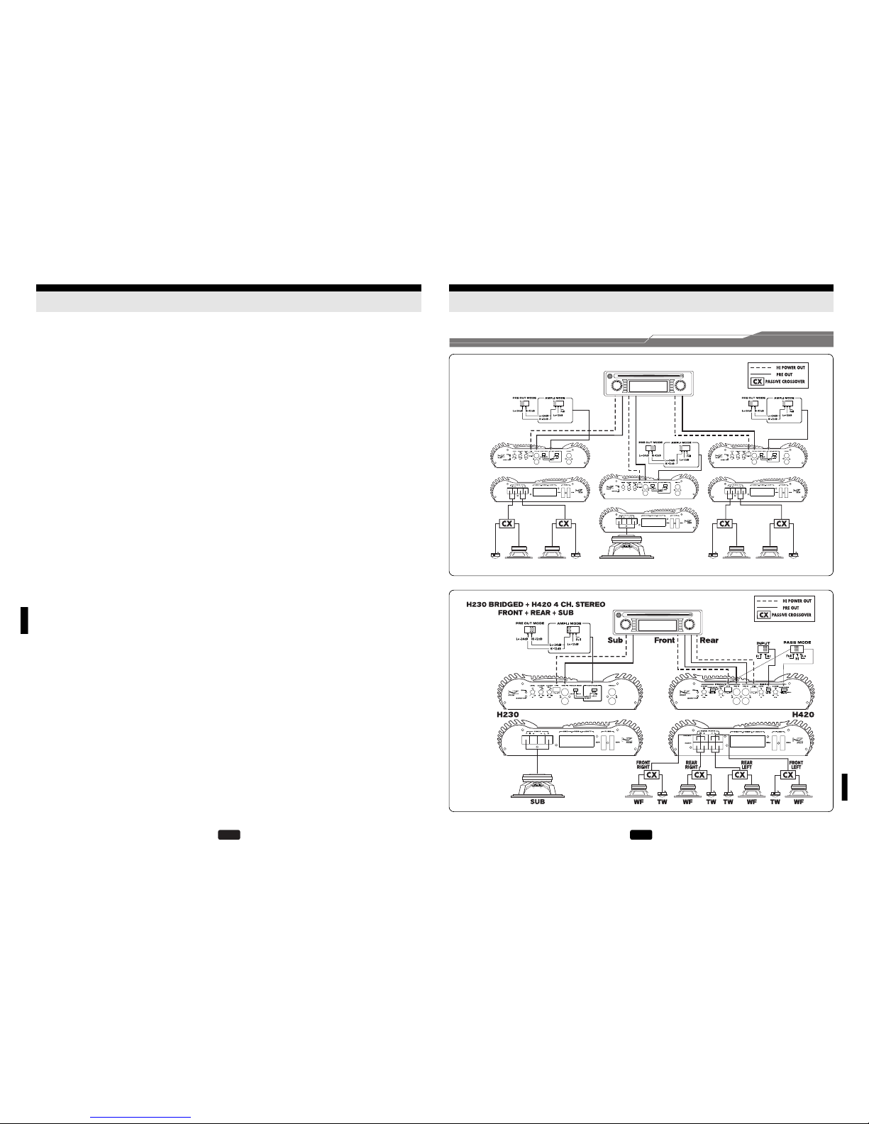
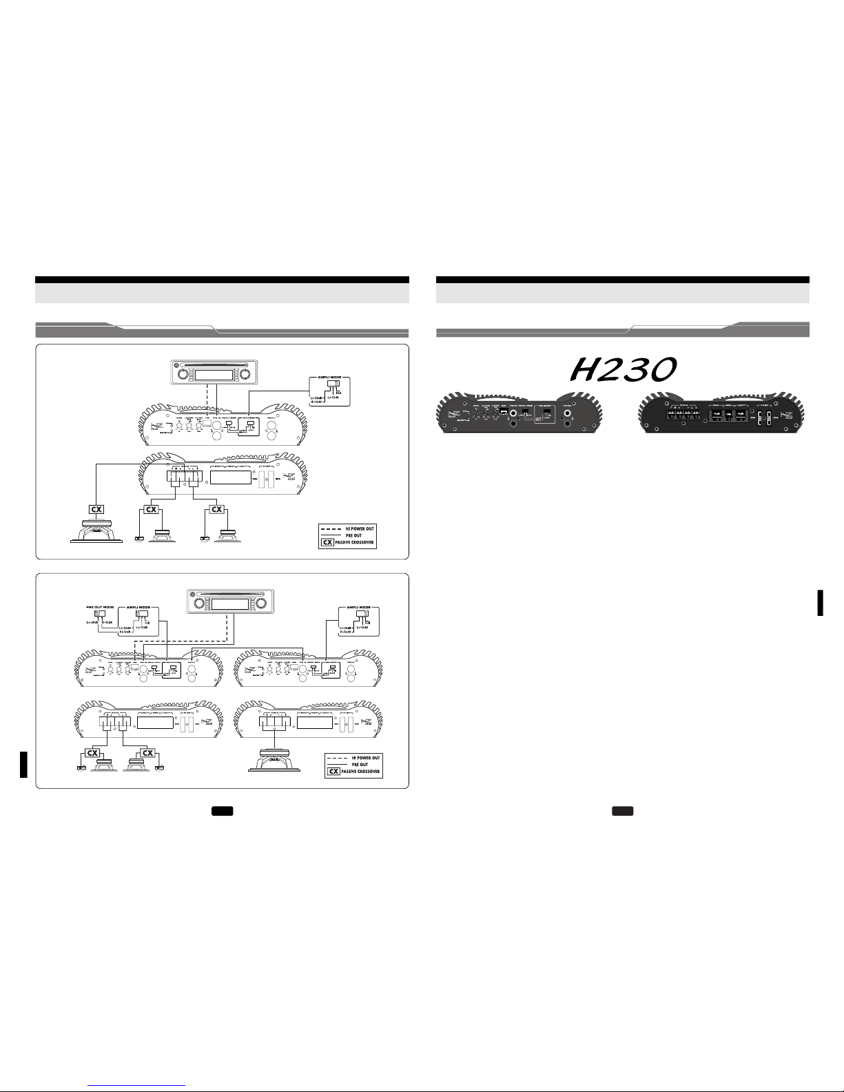
impegnative quali, tra le altre, la costruzione di un sistema completo, fronte
anteriore più subwoofer, in modalità Trimode o il pilotaggio di un subwoofer
mono con filtro a 24 dB/Oct. La compatibilità assoluta con qualsiasi sorgente
è garantita dalla possibilità di accettare segnali preamplificati fino a 5V e segnali
ad alto livello per le autoradio equipaggiate soltanto con le uscite di potenza (HI
POWER). La grande riserva di potenza, l'energico controllo in bassa frequenza e
la precisione timbrica rendono l'HERTZ H230 l'amplificatore ideale per fornire
elevate pressioni sonore e prestazioni musicali d'alto livello.
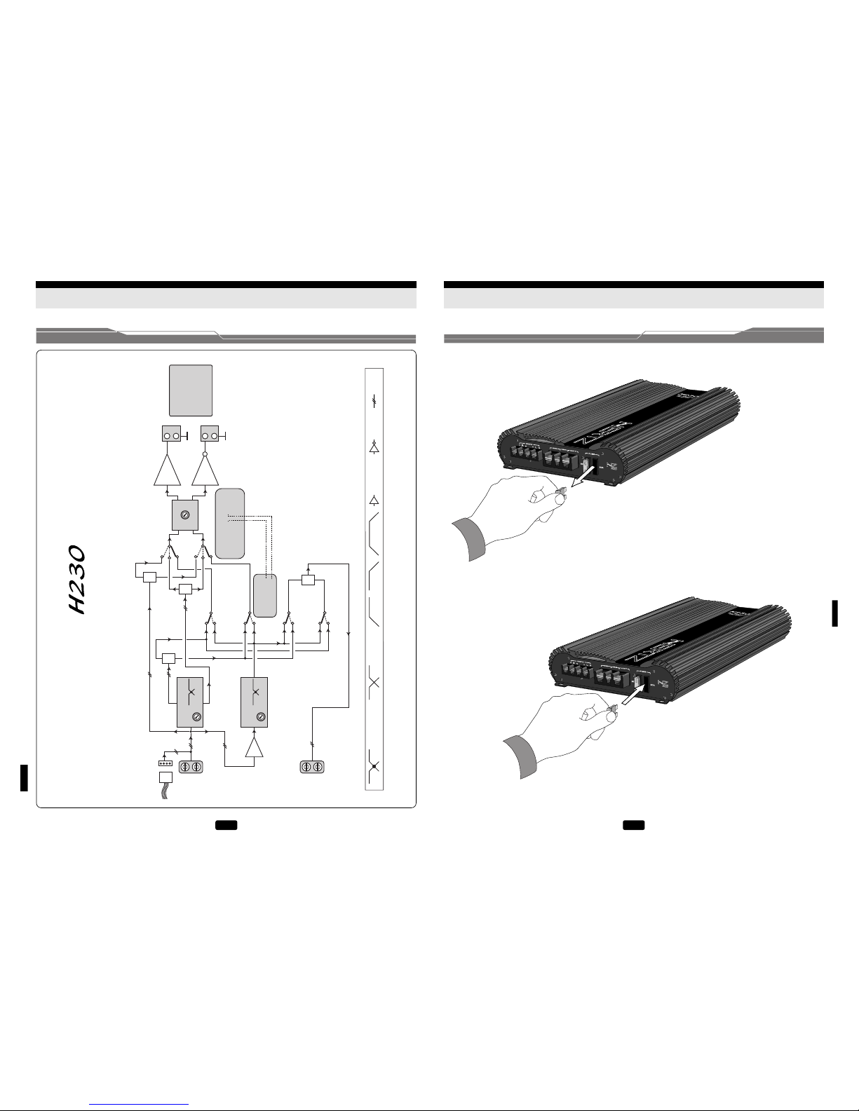
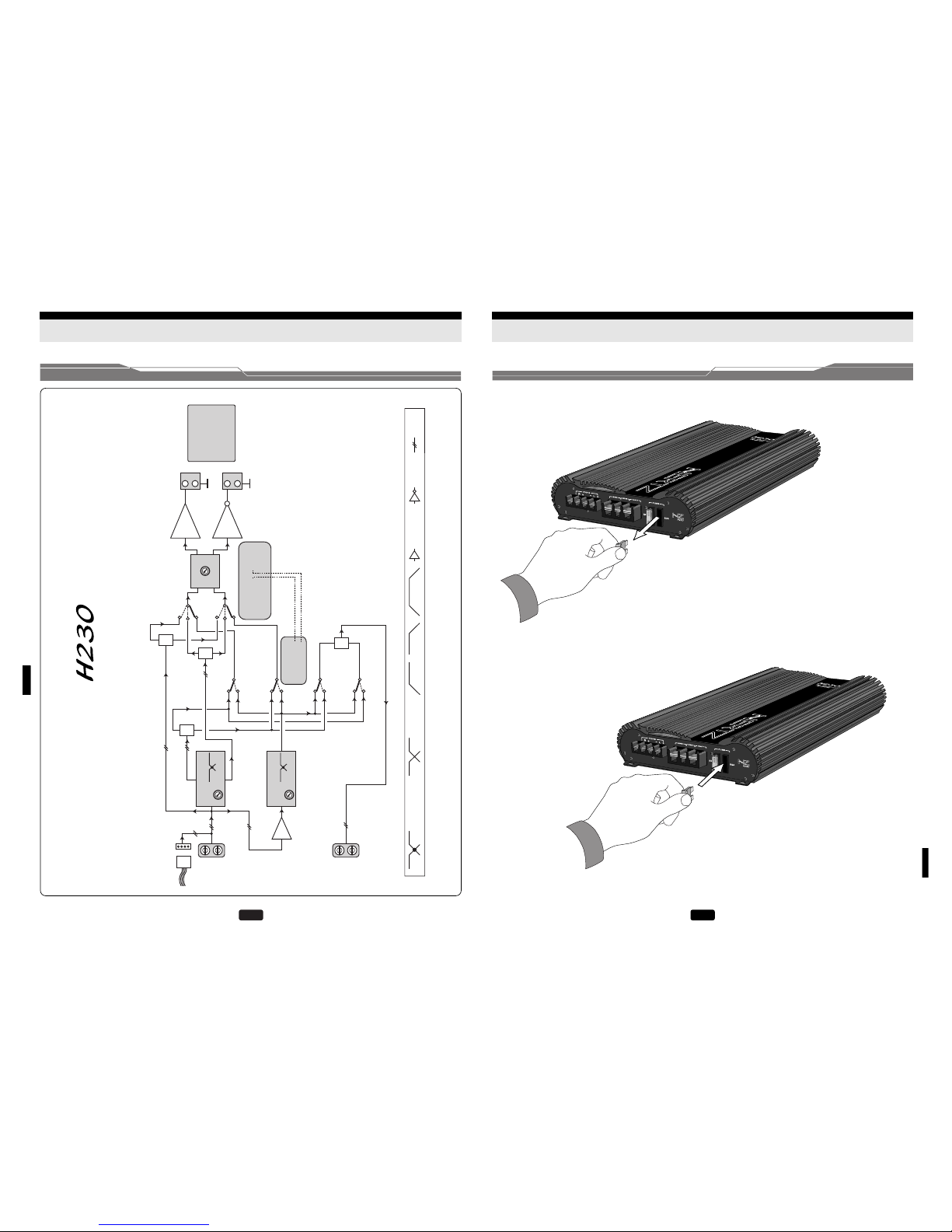
SEZIONE D’ALIMENTAZIONE
L’ H230 dispone di due stadi d'alimentazione separati, di tipo switching, ognuno
dei quali pilota un finale in configurazione Dual mono. I singoli stadi sono
realizzati con tre coppie di MOSFET che pilotano un trasformatore toroidale con
avvolgimento multifilare sovradimensionato.
SEZIONE D’INGRESSO
Lo stadio d'ingresso dispone dello speciale circuito NRS®(Noise Reduction
System) per la totale reiezione dei disturbi dell'impianto dovuti alle parti elettriche
del veicolo (alternatore, iniezione elettronica, ecc.).
SEZIONE FINALE
Gli stadi driver, caratterizzati da una circuitazione estremamente lineare a
bassissima distorsione armonica ed elevato fattore di smorzamento, sono dotati
di un differenziale a transistor. Le sezioni di potenza adottano una configurazione
Darlington con transistor ad alto guadagno e driver bipolari ad elevata corrente
in grado di erogare potenze comprese fra 230W per canale in configurazione
stereo e 700W in mono.
SEZIONE CROSSOVER
L'HERTZ H230 dispone di un crossover elettronico escludibile costituito da due
filtri di tipo Butterworth con pendenza selezionabile tra 12 e 24 dB/Oct. Tramite
la regolazione della frequenza di taglio del filtro compresa fra 40 e 150 Hz e la
selezione del tipo di segnale (Hi-Pass/Lo-Pass), l'amplificatore è in grado di
gestire qualsiasi sistema di altoparlanti, anche in configurazione mono.
Attraverso il selettore AMPLI MODE e PRE OUT MODE è possibile gestire le
uscite preamplificate con segnale di tipo Hi-Pass o Lo-Pass mono.
PROTEZIONI
Le protezioni dell'HERTZ H230 prevedono:
•dispositivo contro il cortocircuito e la presenza di DC (corrente continua) sulle
uscite a salvaguardia degli altoparlanti;
•sensore termico. In caso di aumento eccessivo della temperatura interrompe il
funzionamento dell'amplificatore fino al ripristino delle condizioni ottimali.
60
ANLAGENBEISPIELE