Herutu WCP-LR16U User manual

Simple Contact Wireless Transfer Unit
WCP-LR16U
INSTRUCTION MANUAL V1.00
Please use this operation manual correctly on reading well.
Please keep it carefully to be able to read immediately, when required.


Table of Contents
1.Outline...................................................................................................................................................................1
2.Body andAccessories...........................................................................................................................................2
2-1.WCP-LR16U...................................................................................................................................................2
2-2.Options...........................................................................................................................................................2
3.Safety Precautions (Be Sure to Read This)..........................................................................................................3
4.Names and functions of each part........................................................................................................................6
4-1.Names of each part........................................................................................................................................6
4-2.About LED for monitoring...............................................................................................................................7
5.How to use............................................................................................................................................................8
5-1.Use procedure................................................................................................................................................8
6.Functions and settings........................................................................................................................................10
6-1.Configuration switch.....................................................................................................................................10
6-1-1.Communication channel settings..........................................................................................................11
6-1-2.Set number settings ..............................................................................................................................11
6-1-3.Terminal input/output settings ...............................................................................................................12
6-1-4.Setting the periodic transmission time..................................................................................................13
6-1-5.Setting the input judgment time.............................................................................................................14
6-1-6.Setting the communication mode..........................................................................................................15
6-1-7.Startup of the Communication environment checking function............................................................16
7.Installation and connection .................................................................................................................................17
7-1.Installation....................................................................................................................................................17
7-2.Installation location.......................................................................................................................................18
7-3.Connection to the terminal block..................................................................................................................19
7-3-1.Power input terminal block....................................................................................................................19
7-3-2.Error output terminal block....................................................................................................................19
7-3-3.I/O terminals..........................................................................................................................................20
7-3-4.Connection cable...................................................................................................................................22
7-4.Communication environment checking function..........................................................................................23
8.Communication...................................................................................................................................................24
8-1.Communication type ....................................................................................................................................24
8-2.communication error output.........................................................................................................................25
9.Notes for use.......................................................................................................................................................26
9-1.Response time .............................................................................................................................................26
9-2.Selecting communication channel ...............................................................................................................27
10.Specification......................................................................................................................................................28
11.Dimensions Drawing .........................................................................................................................................29
12.Troubleshooting.................................................................................................................................................31
13.After service and Warranty................................................................................................................................33
1
1.Outline
WCP-LR16U is a simple contact wireless transfer unit using the 920 MHz band wireless communication. The
device wirelessly transfers contact signals from external devices. Use of the device enables wireless transfer of
up to 16 contacts between manufacturing facilities and industrial equipment that are located far from each other.
Wireless communication with 920 MHz band LoRa modulation achieves reliable communication.
The device is configured to be used in pairs(1:1).
<Features>
◆The configuration is 1:1.
◆With 920 MHz band LoRa modulation, highly reliable bi-directional communication is achieved.
◆Operation settings can be easily performed with the configuration switches.
◆Selectable from 15 wireless channels.
◆The communication mode can be selected from “Standard mode” and “Long- range mode”.
◆The transfer method of contacts can be selected from “uni-directional 16 contacts” and
“bi-directional 8 contacts”.
◆You can check the wireless communication status and terminal input/output status with the LED for
Monitoring.
◆When using the terminals in the input setting, you can switch between “Voltage contact input” and
“Non-voltage contact input”.
◆You can determine the installation location using “Communication environment checking function” that
displays the communication environment between the paired units in 5 levels.
◆When a wireless communication error occurs, you will be notified by lighting of the LED for Error Indication
and an error output.
◆The power supply is DC24V±10%.
The device can be used withAC100-240V by using the optional AC adapter.
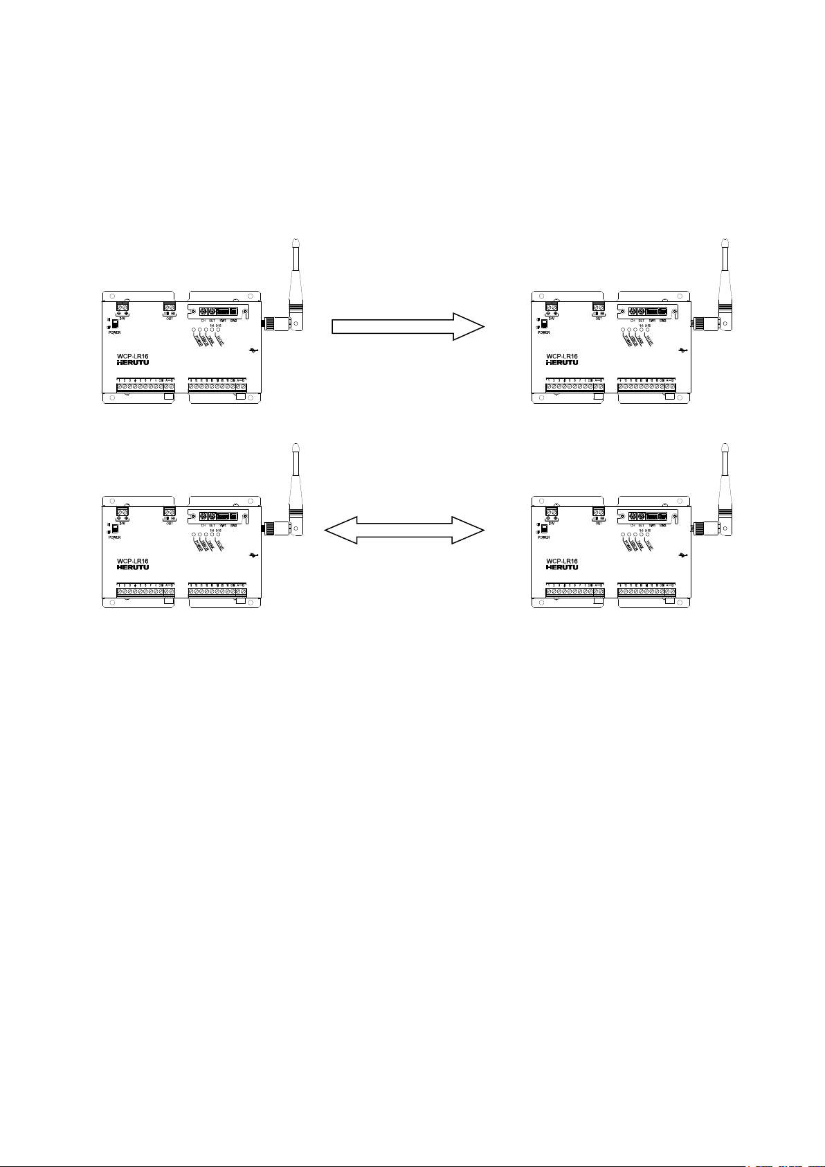
uni-directional 16 contacts
bi-directional 8 contacts

2
◆In Standard mode, “communication distance of approx. 300m(328yd) indoors / approx.1,000m (1,094 yd) in
line of sight”, and in Long-range mode, the communication distance can be extended to “communication
distance of approx. 2,000m (2.187 yd) in line of sight”. (※depending on usage conditions)
As demo units are available, it is recommended to perform a communication test, etc. in advance.
2.Body and Accessories
2-1.WCP-LR16U
2-2.Options
・Antenna mounting kit(cable 3m)SMAR3-3D2V
The kit is a set of a bracket and coaxial cable. The supplied dipole antenna can be installed away from the
main unit.
・AC Adapter ADB24050-F (With connection cable)
WCP-LR16U body ×1
Cable 1.5m
Connection cable 1.8m
Dipole antenna ×1
(MEGWX-467XRSBX-920)
Insertion bridge ×2
※Shipped mounted on "A-B" terminal
block.端子台(A-B)に取り付けて出荷
Bracket
Coaxial cable
3.0m
Examples of Use
Table of contents
Popular Test Equipment manuals by other brands


Redtech
Redtech TRAILERteck T05 user manual

Venmar
Venmar AVS Constructo 1.0 HRV user guide

Test Instrument Solutions
Test Instrument Solutions SafetyPAT operating manual

Hanna Instruments
Hanna Instruments HI 38078 instruction manual

Kistler
Kistler 5495C Series instruction manual

Waygate Technologies
Waygate Technologies DM5E Basic quick start guide

StoneL
StoneL DeviceNet CK464002A manual

Seica
Seica RAPID 220 Site preparation guide

Kingfisher
Kingfisher KI7400 Series Training manual

Kurth Electronic
Kurth Electronic CCTS-03 operating manual

SMART
SMART KANAAD SBT XTREME 3G Series user manual

Agilent Technologies
Agilent Technologies BERT Serial Getting started