Herutu TW-850T User manual

POKAYOKE (MISTAKE PREVENTION) TOOLS
TW-850T
Instruction Manual V1.00
Please use this Instruction manual correctly on reading well.
Please keep it carefully to be able to read immediately, when required.


Table of Contents
1. Overview...............................................................................................................................................................1
2. Main part and accessories .................................................................................................................................2
3. Safety Precautions (Be Sure to Read This)......................................................................................................3
4. Name and Function of Each Part.......................................................................................................................7
5. Attachment of TW-850T ......................................................................................................................................8
6. Setting.................................................................................................................................................................11
7. How to Use the transmitter...............................................................................................................................12
8. Specifications....................................................................................................................................................14
9. Dimensions Drawing.........................................................................................................................................15
10. Before Determining Fault ...............................................................................................................................16
11. When something is wrong..............................................................................................................................17

TW-850T
1
1. Overview
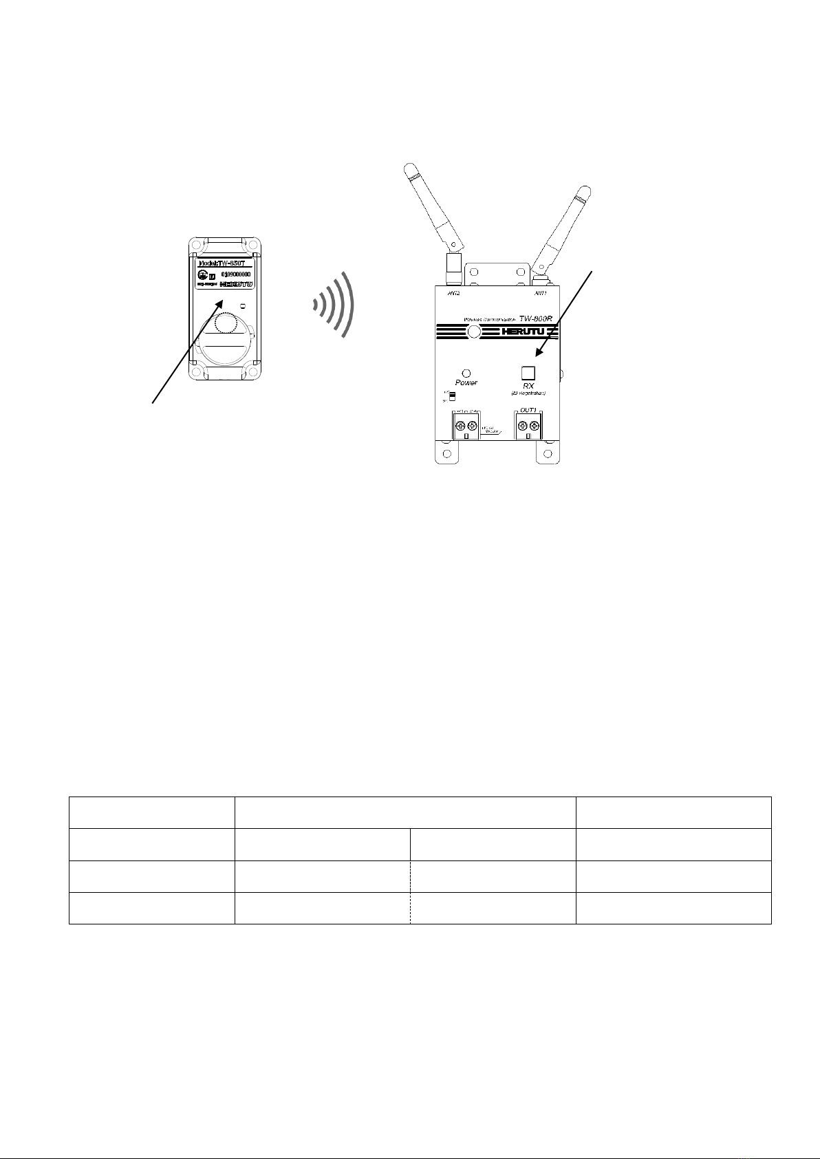
“TW-850T”(below referred to as “the transmitter”)is a Pokayoke compact transmitter that can be attached to
Pokayoke compatible tools, except torque wrenches and pliers wrenches.
The transmitter can be attached to various Pokayoke-compatible tools to transmit work completion signals to
receivers wirelessly.
The transmitter can communicate with a Pokayoke receiver “TW-800R-***” series.
<Features>
◆Reliable communication
The transmitter can communicate automatically by selecting the channel from 76ch in 2.4GHz bandwidth.
The transmitter transmits the signal reliably by 2way communication.
◆The lighting / blinking transmitter LED indicates wireless communication OK/NG.
◆When wireless communication fails, the transmitter notifies users of the problem by causing the LED to blink
and sounding the buzzer at the same time.
◆Battery level notification function
A function to notify when the battery level is low (when press with test switch) or when the battery needs to be
replaced.
The battery level will be notified by both the transmitter and receiver LEDs when the battery level is low and
will be notified by the transmitter LED when the battery needs to be replaced.
◆Uses a small and lightweight coin battery as a power source.
◆Easy battery replacement
◆Battery life of about 300,000 uses. (depending on usage conditions)
◆Communication distance of approx.30m indoors (varies depending on the operating environment).
◆Available countries:Japan, Canada, USA, Mexico, China, Thailand, Vietnam, Philippines and India.
TW-850T
2
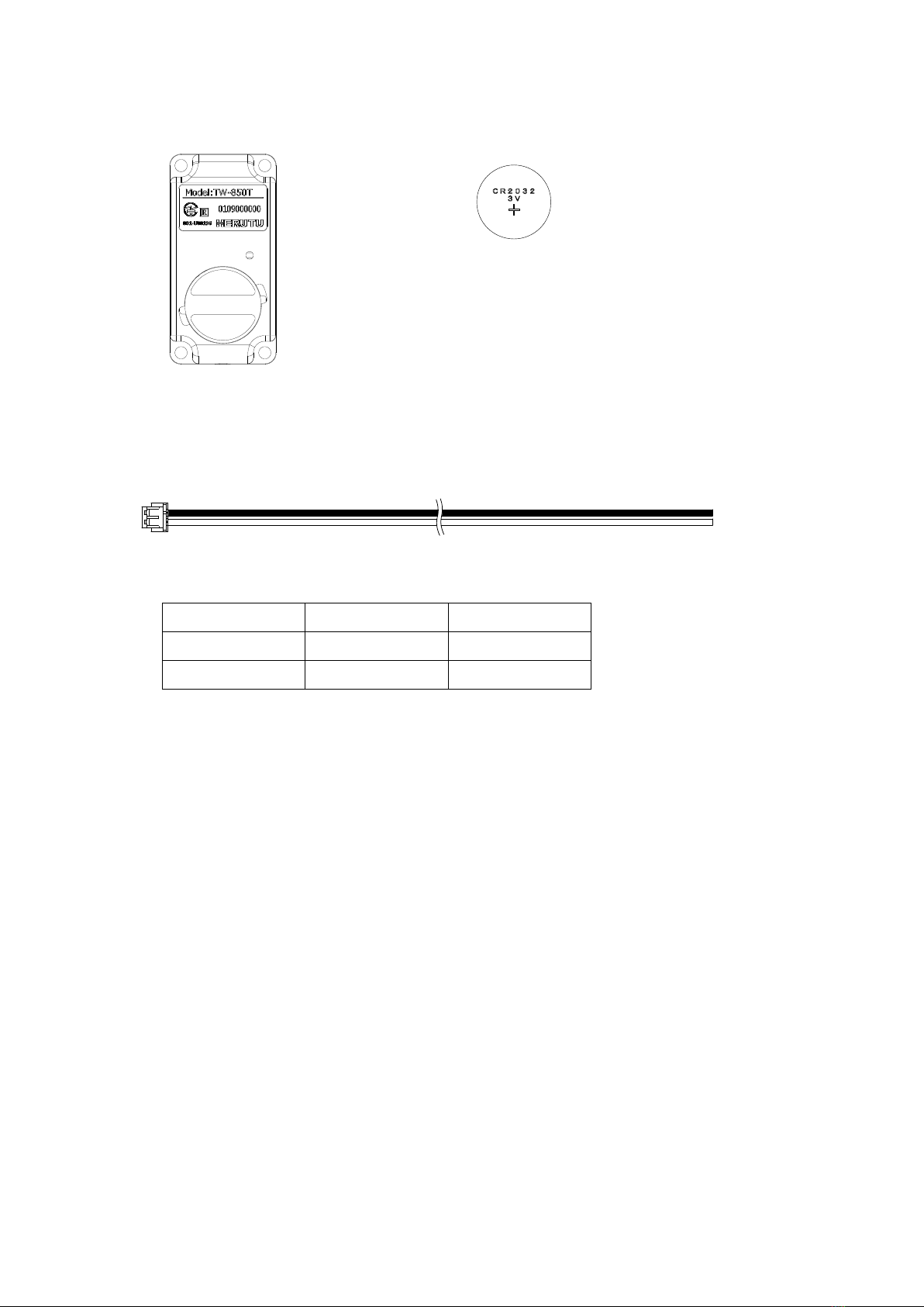
2. Main part and accessories
・Transmitter TW-850T ・Coin battery CR 2032
・Cable with a connector
Connect the cable to the cable connecting connector of the main body.
Cable color
Terminal No.
Terminal name
Black
1
GND
White
2
IN
*TW-850T is delivered with a coin
battery installed.
(Cable lengthApprox.200mm)
Connector
(ZHR-2 made by JST)
ケーブル色
端子番号
端子名
黒色
1
GND
白色
2
OC
(JST 製ZHR-2)

TW-850T
3
3. Safety Precautions (Be Sure to Read This)
This section describes the matters to be observed in order to prevent harm to the users and other persons and
damages to the property.
■The following marks and displays classify and describe the extent of harm and damage caused by failing to observe
the display content and using this product wrongly.
This display column shows "a failure to do observe it could result in only the personal
injury or property damage".
■Handling this product
⚫This product is the wireless communication equipment made of precision parts. Do not
disassemble or modify it. Or the accident or fault may occur.
■Use and storage environment
⚫DO NOT USE OR STORE the product in the following places to prevent defects, malfunction,
deterioration, fire, and electric shock:
•Do not use and store it in places exposed to direct sunlight,
•Do not use and store it in places where liquids, foreign substances, corrosive gases or
combustible gases can enter the product,
•Do not use and store it in places with high humidity or where there is abundant oil smoke,
dust, sand, etc. ,
•Do not use it in an unstable place such as a wobbling table or an inclined plane,
•Do not use it in a place with vibration.
■Specific handling of this product
This product is a radio equipment with certification of construction design.
⚫It is prohibited by law to disassemble or modify certified devices.
⚫Do not remove the certification label affixed to the case. It is prohibited to use any product
without the label.
⚫This product is only available in the countries where the certification is acquired.
This display column shows "a failure to do observe it could result in death or
serious personal injury".
■Handling this product
⚫Do not use this product for application that requires the extremely high reliability affecting the
human life.
⚫Do not use this product in the area which the radio wave reaches or not.
■If a problem occurs during use
⚫When smoke comes or there is a strange smell, immediately stop usage and remove the power
plug from the outlet because it may cause fire and electric shock. Request the dealer or our
company to repair it.
!
Warning
!
Caution

TW-850T
4
■Notes on the Radio Law
〇The wireless device used for this product is certified as a specific radio device for a radio equipment of a low power
data communication system based on the Radio Law. Therefore, a radio station license is not required to use this
product.
〇This product can be used only in Japan or countries where required certification is acquired. In the case that it is
used in other countries, this product may be damaged or it may damage other equipment. It also may conflict with the
laws of that country. Please contact our sales department for the countries that the product is certified other than
Japan.
〇Do not use this product near any person using cardiac pacemaker. The cardiac pacemaker may be disturbed by
electromagnetic wave, which may cause risk of life.
〇Do not use this product near any medical equipment. The medical equipment may be disturbed by electromagnetic
wave, which may cause risk of life.
〇Do not use this product near any microwave oven. Electromagnetic wave from microwave oven may disturb radio
communication.
〇The wireless device of this product is certified under the Radio Law, so that DO NOT disassemble or remodel this
product.
■Notes on radio interference of 2.4 GHz radio
When communicating with 2.4 GHz band wireless products, pay attention to the following points.
In this product’s frequency band not only industrial, scientific and medical equipment such as microwave ovens but also
local radio stations for mobile objects identification (which require the license), specified low-power radio stations
(license not required), and amateur radio stations (license required) can be in operation.
〇Before using this product, make sure that there are no local radio stations for mobile objects identification, specified
low-power radio stations and amateur radio stations operating nearby.
〇In event that harmful interference occurs to any radio station by the radio wave from this product, stop using it
immediately and consult with us about avoiding interference.
〇Also contact us in case of any trouble such as harmful radio interference to specified low-power radio stations for
mobile objects identification or amateur radio stations.
TW-850T is equipped with the built-in wireless module HRF-2402.
Available countries:Japan, Canada, USA, Mexico, China, Thailand, Vietnam, Philippines and India.

TW-850T
5
■FCC/IC Warning
Information about FCC Standard.
FCC CAUTION
Change or modifications not expressly approved by the party responsible for compliance could void the
user’s authority to operate the equipment.
This transmitter must not be co-located or operated in conjunction with any other antenna or transmitter.
This equipment complies with FCC radiation exposure limits set forth for an uncontrolled environment
and meets the FCC radio frequency (RF) Exposure Guidelines. This equipment has very low levels of
RF energy that is deemed to comply without maximum permissive exposure evaluation (MPE).
This equipment complies with FCC radiation exposure limits set forth for an uncontrolled environment
and meets the FCC radio frequency (RF) Exposure Guidelines. This equipment has very low levels of
RF energy that is deemed to comply without testing of specific absorption rate(SAR).
I Information about ISED Standard.
This device complies with Industry Canada’s applicable license-exempt RSSs. Operation is subject to
the following two conditions:
(1) This device may not cause interference; and
(2) This device must accept any interference, including interference that may cause undesired operation
of the device.
Le présent appareil est conforme aux CNR d’Industrie Canada applicables aux appareils radio exempts
de licence. L’exploitation est autorisée aux deux conditions suivantes :
1) l’appareil ne doit pas produire de brouillage;
2) l’utilisateur de l’appareil doit accepter tout brouillage radioélectrique subi, même si le brouillage est
susceptible d’en compromettre le fonctionnement.
This equipment complies with IC radiation exposure limits set forth for an uncontrolled environment and
meets RSS-102 of the IC radio frequency (RF) Exposure rules. This equipment has very low levels of
RF energy that is deemed to comply without maximum permissive exposure evaluation (MPE).
Cet équipement est conforme aux limites d’exposition aux rayonnements énoncées pour un
environnement non contrôlé et respecte les règles d’exposition aux fréquences radioélectriques (RF)
CNR-102 de l’IC. Cet équipement émet une énergie RF très faible qui est considérée comme conforme
sans évaluation de l’exposition maximale autorisée (MPE).
This equipment complies with IC radiation exposure limits set forth for an uncontrolled environment and
meets RSS-102 of the IC radio frequency (RF) Exposure rules. This equipment has very low levels of
RF energy that is deemed to comply without testing of specific absorption rate (SAR).
Cet équipement est conforme aux limites d’exposition aux rayonnements énoncées pour un
environnement non contrôlé et respecte les règles d’exposition aux fréquences radioélectriques (RF)
CNR-102 de l’IC. Cet équipement émet une énergie RF très faible qui est considérée comme conforme
sans évaluation du débit d’absorption spécifique (DAS).
TW-850T
6
This radio transmitter (10608A-HRF2402) identify the device by certification number or model number if
Category II) has been approved by Industry Canada to operate with the antenna types listed below with
the maximum permissible gain indicated. Antenna types not included in this list, having a gain greater
than the maximum gain indicated for that type, are strictly prohibited for use with this device.
Antenna type:1/4λ Dipole antenna (chip antenna) Gain: 3dBi
Antenna type:1/2λ Dipole antenna Gain: 2dBi
Antenna type:1/2λ Dipole antenna Magnet Base Gain: 2dBi
Le présent émetteur radio (10608A-HRF2402) a été approuvé par Industrie Canada pour fonctionner
avec les types d'antenne énumérés ci-dessous et ayant un gain admissible maximal. Les types
d'antenne non inclus dans cette liste, et dont le gain est supérieur au gain maximal indiqué, sont
strictement interdits pour l'exploitation de l'émetteur.
Type d’antenne:1/4λ Dipole antenna (chip antenna) Gain: 3dBi
Type d’antenne:1/2λ Dipole antenna Gain: 2dBi
Type d’antenne:1/2λ Dipole antenna Magnet Base Gain: 2dBi
■Thailand Radio Law (SDoC)
This telecommunication equipment is in compliance with NBTC requirements.
■Information about IFETEL(Mexico)
IFETEL RCPHEHR19-1206
HERUTU
HRF-2402
La operación de este equipo está sujeta a las siguientes dos condiciones: (1) es posible que este equipoo
dispositivo no cause interferencia perjudicial y (2) este equipo o dispositivo debe aceptar cualquier
interferencia, incluyendo la que pueda causar su operación no deseada.
TW-850T
7
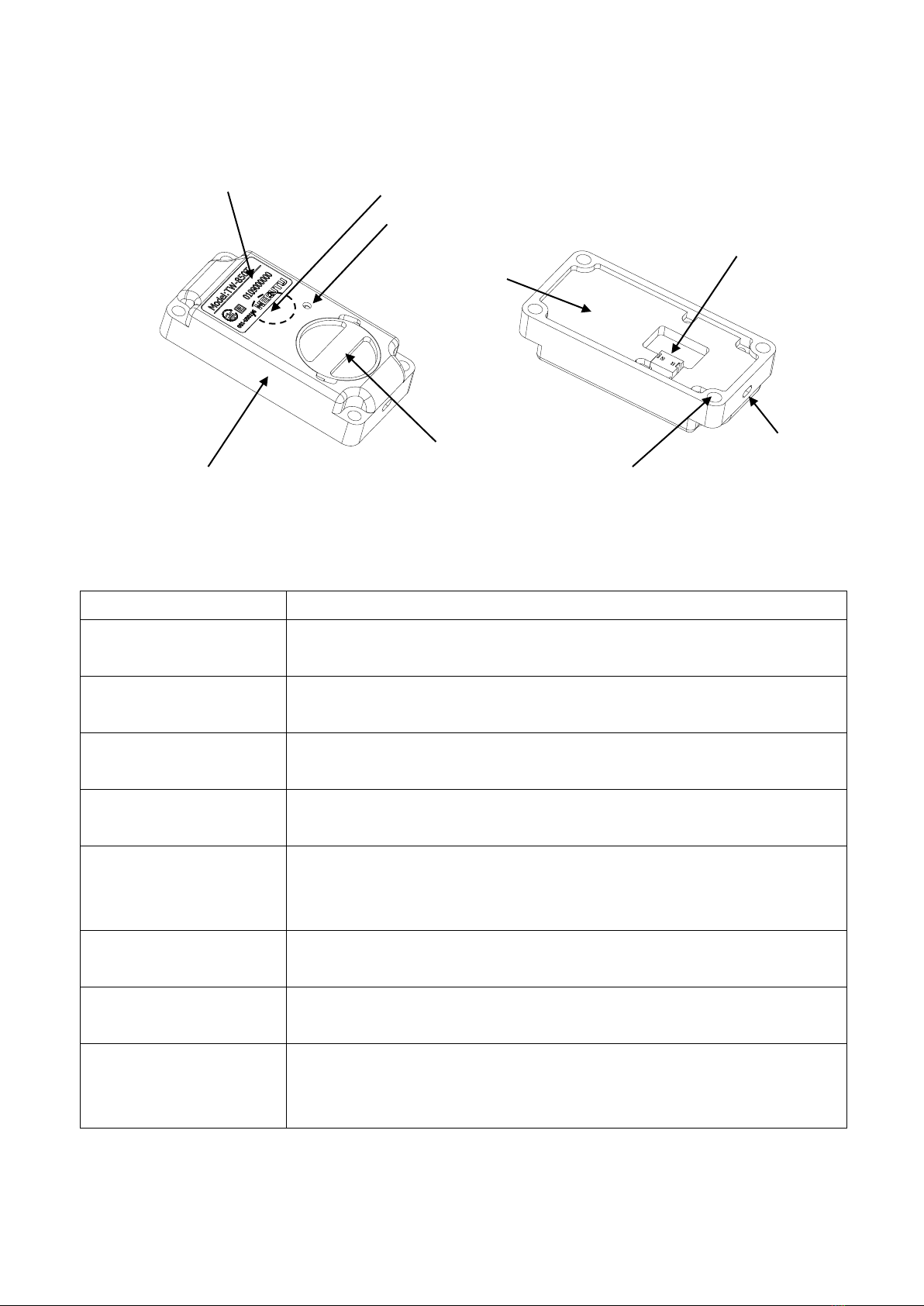
4. Name and Function of Each Part
①Main body case
Main body case. POM, a highly durable material, is used.
②Battery cap
Lid for fixing the coin battery (CR2032).
The transmitter is delivered with a coin battery installed.
③Protective cover
Cover for protecting the internal components of the main body.
POM, a highly durable material, is used.
④Monitor LED(green/red)
An LED for communication confirmation/battery check. It lights up/blinks
green/red according to the communication result.
⑤Test switch
(Pairing switch)
Used for testing wireless communication or for pairing.
⑥Harness connecting
connector
Connector for connecting the supplied cable with connector.
A wireless signal is transmitted by the work completion signal input
(No-voltage contact input) to the connector.
⑦Buzzer hole
When the buzzer of the transmitter is activated, the sound comes out of the
hole.
⑧Main body mounting
hole
Mounting hole for fixing the main body to a Pokayoke tool.
Four mounting holes are provided. Use M3 screws to fix the main body.
⑨Nameplate label
Nameplate label of the product. Model No. and serial No. are indicated on
the label.
Serial No. on the label represents the ID No. of the transmitter.
①Main body case
②Battery cap
④Monitor LED
⑤Test switch(pairing switch)
③Protective cover
⑧Main body mounting hole
(4 places)
⑦Buzzer hole
⑥Harness connecting connector
⑨Nameplate label

TW-850T
8
5. Attachment of TW-850T
<Cable connecting connector>
Connector for connecting the supplied cable with connector.
Connector model:S2B-ZR-SM4Amade by JST
Terminal
No.
Terminal
Name
Input condition
1
GND
Connect GND to the ground.
2
IN
Terminal for input of the work completion signal (Non-voltage contact
input).A wireless signal is transmitted by a continuous signal input for
about 40mSEC or longer.
・Input circuit diagram
<Connecting method for the cable with connector>
Connect the cable with connector firmly as shown below.
The connector cannot be inserted in the wrong orientation.
Cable with a connector
Connector model:ZHR-2 made by JST
Cable color
Terminal No.
Terminal name
Black
1
GND
White
2
IN
Cable connecting connector
(S2B-ZR-SM4Amade by JST)
To Microcomputer

TW-850T
9
●Connection examples
The area surrounded by dotted lines represents the supplied cable with connector.
Connecting a switch
Connecting a photocoupler/photo MOS relay
Connecting a transistor
<Input Judgment time for transmitter>
The transmitter is designed not to transmit signals when the signal input time from the limit switch is 40ms or
less. This prevents the transmitter from accidentally transmitting signals when dropping the Pokayoke
compatible tools.
Due to the above mechanism, the transmitter may not transmit signals even after hitting the limit switch with
your finger, etc. for transmitting test signals.
Black
White
Black
White
Black
White
TW-850T
10
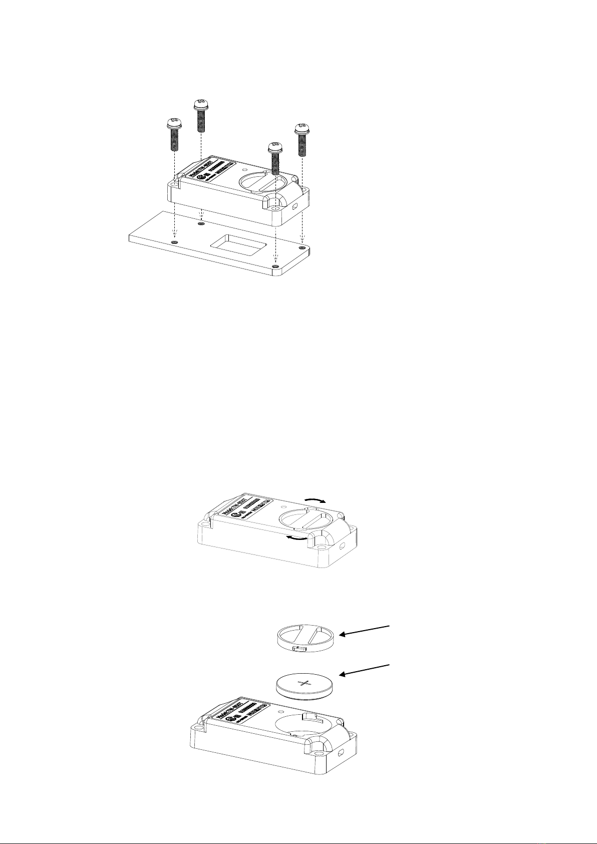
<Attachment of the transmitter>
Attach the transmitter using the main body mounting holes on the main body case and fix it with four
M3 screws. ※M3 screws are not included.
When using metal as fixing material, it is recommended to use metal with plate thickness of 2 mm or more
(1mm or more for burring). For transmitter fixing screws, pan small screws with spring washer M3*10 mm or
larger are recommended.
When using resin as fixing material, it is recommended to use resin with plate thickness of 5 mm or
more(except when using an insert nut, etc.). For transmitter fixing screws, pan small screws with spring washer
M3*12 mm or larger are recommended.
<Insertion or removal of the battery>
To close the battery cap, turn the battery cap securely in the direction of arrow shown below until it snaps into
place.To remove the battery cap, turn the battery cap in the opposite direction from the arrow shown below.
When replacing the battery, be sure to insert the coin battery with the correct polarity.
Battery cap
Coin battery (CR2032)

TW-850T
11
6. Setting
The transmitter and a Pokayoke receiver TW-800R-*** need to be paired before use.
By pairing them, they recognize an identification signal from each other and communicate with each other.
This manual describes how to pair the transmitter with the receiver TW-800R.
For pairing with a receiver other than TW-800R, see the instruction manual of each receiver.
⚫Pairing (registration)
①Press the lighting switch for paring of the receiver, and turn ON the power switch at the same time.
The lighting switch for paring blinks and the receiver enters the pairing mode for 10 seconds.
②Long press the pairing switch of the transmitter for 3 seconds or longer.
③The lighting switch for paring of the receiver goes out and pairing is complete.
④Turn OFF the power of the receiver once and turn it ON again, and the receiver can communicate with the
paired transmitter.
⚫Reset pairing
①Press the lighting switch for paring of the receiver, and turn ON the power switch at the same time.
The lighting switch for paring blinks and the receiver enters the pairing mode for 10 seconds.
Long press the lighting switch for paring for 2 seconds or longer, and the lighting switch for paring lights
up and the paired (registered) data of the transmitter is deleted.
◆Notes
A long press on the pairing switch of the transmitter (3 seconds or more) when the receiver is not in the pairing
mode resets the pairing with the receiver and prevents communication with the registered receiver. When pairing
is reset by mistake, perform the pairing procedure again.
Lighting switch for paring
Power switch
Pairing switch
(Test switch)
TW-850T
12
7. How to Use the transmitter
①Turn ON the power switch of the receiver. Make sure the receiving LED is OFF.
When the receiving LED lights up, the transmitter is not paired. Pair the receiver and transmitter.
②A wireless signal is transmitted by inputting a work completion signal to the transmitter.
When wireless communication is normally executed, the receiver generates a relay output and the buzzer of
the receiver is activated according to the settings. The green LED of the transmitter blinks once.
When the communication is not executed normally, the receiver is not activated.
The red LED of the transmitter blinks 10 times, and the buzzer of the transmitter sounds in synchronization with
the red LED.
While the receiver is generating a relay output or preventing a double count, the receiver returns a BUSYsignal
to the transmitter. When the transmitter receives a BUSY signal, the green LED blinks four times, and the
buzzer of the transmitter sounds in synchronization with the green LED.
Transmitter
Receiver
Communication OK
Green LED blinks 1 time
No buzzer sound
Receiving LED blinks 1 time
Communication Failed
Red LED blinks 10 times
Buzzer sounds 10 times
-
BUSY
Green LED blinks 4 times
Buzzer sounds 4 times
-
The buzzer sounding time of the receiver is normally 100 msec. Only when the relay output time is set to 50
msec. and the double count prevention time is set to 10 msec., the buzzer sounding time is 50 msec.
※When the transmitter not paired with receiver transmits signals, the red LED blinks three times, and the
buzzer of the transmitter sounds in synchronization with the red LED.
Receiving LED (Green)
(Lighting switch for paring)
Monitor LED (green/red)

TW-850T
13
●Test switch
The transmitter is equipped with a test switch for communication and battery voltage checks.
When the transmitter transmit the signal by test switch not limit switch, receiver doesn’t output relay output. But
LED of receiver only turns on. When the test switch is pressed, the transmitter checks the battery remaining
capacity. The result is indicated by the transmitter LED or the Receiver LED.
The test switch also can be used as a pairing switch. A long press on the test switch (3 seconds or more) resets
the pairing with the receiver and prevents communication with the registered receiver. When pairing is reset by
mistake, perform the pairing procedure again.
Transmitter
Receiver
Communication check OK
Green LED blinks 1 time
No buzzer sound
Receiving LED blinks 1 time
Communication check Failed
Red LED blinks 10 times
Buzzer sounds 10 times
-
Battery level low
Red LED lights for 1 second
No buzzer sound
Receiving LED blinks 2 times
※After display of the communication check result (Communication OK/ NG), the transmitter indicates battery
level low.
●Battery level notification function
The battery level notification function notifies the battery level status in two stages.
①Notification of low battery level with test switch: It is possible to check the battery level with the test switch.
When the battery is low, the red LED will light for 1 second.
②Battery replacement notice: If the battery level is lower than in ①and the battery needs to be replaced,
the green LED flashing after transmission will change to an orange LED flashing.
When the orange LED blinks, please replace it with a new battery immediately.
When you replace the battery with a new one, the LED on the transmitter will return to green from the second
and subsequent transmissions.
Test switch
For transmitter that support the battery level
notification function(battery replacement notice),
■is printed on the sticker.

TW-850T
14
8. Specifications
Item
Specifications
Compliance Standards
<Japan>
Radio equipment specified in Article 2 paragraph 1 item(19) of the Radio Law
*Specialized radio equipment: Low power data communication system in the
2.4 GHz band
Article 49-20 paragraph 1 of the Ordinance Regulating Radio Equipment
<USA:FCC / Canada:ISED> FCC Part.15-247
<Thailand:NBTC> SDoC
<India:ETA> ETA-848/2017-RLO(SR)
<Mexico:IFETEL>
Radio format
F1D
Frequency Band
2,403MHz~2,478MHz
Number of Channels
76CH
Modulation Method
GFSK
Communication Method
Simplex
Antenna Power
2.1mW
Input(s)
1 Non-voltage contact input
1 Test Switch
Output(s)
Piezoelectric buzzer 72dB/0.3m
Display
1 LED(Red/Green)
Power Source
1 Coin Battery (CR2032)
Operating Environment
Temperature: 0-50℃(32-122℉)
Humidity: 80% or less (without condensation)
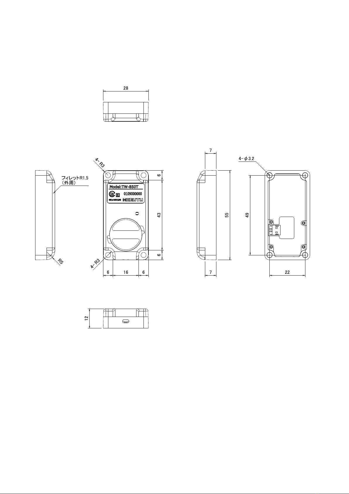
External Dimensions
(W x H x D)
28W×55H×12D mm (Excluding protrusions)
Weight
approx. 25g
Antenna
Chip antenna
Battery Life
Approx. 300,000 uses (depending on usage conditions)
TW-850T
15
9. Dimensions Drawing

TW-850T
16
10. Before Determining Fault
Phenomenon
Cause and remedy
The transmitter does not transmit
LED (red or green) does not light up
Battery capacity is low.
→Please replace the battery (CR2032).
The red LED blinks 3 times after transmitting.
(The buzzer of the transmitter sounds 3 times in
synchronization with the red LED.)
Pairing is not done. (not registered)
→Perform pairing with the receiver to communicate with the
transmitter.
The red LED blinks 10 times after transmitting.
(The buzzer of the transmitter sounds 10 times
in synchronization with the red LED.)
The power of the receiver is not ON.
→Make sure the power of the receiver to communicate with
the transmitter is ON.
The communication distance is too far.
→The distance is beyond the maximum communication
distance of the machine. Install the transmitter in a location
where it can communicate with a receiver.
The antenna installation status of the receiver is not good.
→Check whether or not the receiver’s antenna is
surrounded by obstacles blocking radio waves or placed in
the control panel (iron), and improve the installation status of
the antenna.Also, consider using an external antenna.
Communication cannot be done due to external factors.
→Use of a product using the same frequency band (2.4GHz
band) as this product may prevent communication. Please
contact our Sales Department with your product information.
The green LED blinks 4 times after transmitting.
(The buzzer of the transmitter sounds 4 times in
synchronization with the green LED.)
The receiver is busy.
→ The receiver is generating a relay output or preventing a
double count.
For the settings, refer to the instruction manual of the
receiver.
Red LED lights up for 1 second after pressing
the test switch.
Battery capacity is decreasing.
→Please replace the battery (CR2032).
Pairing cannot be done
The receiver is not in the pairing mode.
→Set the receiver to the pairing mode and press the pairing
switch of the transmitter for 3 seconds or more.

TW-850T
17
11. When something is wrong
If the problem persists even after a remedy action is taken or if it is unclear which remedy action should be taken,
then contact the dealer where the product was purchased or our Sales Department with the following information:
Product name / Serial No. / Service environment,
External equipment connected,
Operating sequence to error initiation, and
Specific description of error, etc.
The user is prohibited by law from disassembling or making modification to the unit or otherwise may be
subject to punishment.
The Company sets forth the Warranty Terms and Conditions herein for the benefit of customer to ensure product
assurance after shipment. In case of failure, the Company will remedy the defect by repair or replacement.
■Warranty Period
Unless otherwise specified, the warranty period is 13 months after shipment of products from the Company. During
the Warranty Period, the Company remedy defect free of charge in accordance with the terms of this Warranty. If you
have any questions concerning remedy and after-sales services during the Warranty Period, please contact your
dealer or our Sales Department.
■Scope of Warranty
In case any failure occurs attributable to the Company during the Warranty Period, the defect will be remedied free of
charge either by repair or replacement with a substitution. To obtain warranty service, contact your dealer or our
Sales Department. The Warranty Period after repair or replacement is 13 months from the date of initial shipment of
the relevant product or 6 months from the date of shipment of the substitution, whichever period of time is greater.
Only the hardware part of the Product is covered.
The Warranty does not apply to the following, even during the Warranty Period.
1.Failure or damage caused by in appropriate handling on the part of customer, such as drop, shock etc. during
transportation or move.
2.Failure caused by disassembly or modification of the main unit by customer.
3.Failure or damage caused by natural disaster, such as fire, earthquake, flood etc. and abnormal voltage.
4.Failure caused by malfunction of devices connected to the Product other than those designated by the Company.
5.The Warranty does not cover accessories such as an AC adopter, an antenna, a connecting cable, etc.
6.The Product that has been repaired, adjusted or modified by a third party.
7.Replacement of consumables or limited-life goods (including batteries).
Consumables and limited-life goods include the following:
①Switches (limit switch, button switch etc.)
②Battery cells, batteries (dry cell, button battery etc.)
③Other goods considered to be consumables or limited-life goods by usage.
8.Failure caused by not using the Product in accordance with the User Guide
Table of contents
Other Herutu Transmitter manuals


Popular Transmitter manuals by other brands


SGM LEKTRA
SGM LEKTRA RPL81 manual

Sentera Controls
Sentera Controls DSMHM-2R Mounting and operating instructions

Stageline
Stageline ATS-10TL instruction manual

enika
enika P8 T Temp/RH MS 03 quick start guide

Community Controls
Community Controls CHAMELEON 318LIPW4CK quick start guide

Michell Instruments
Michell Instruments Pura 2-Wire user manual