Herutu TW-810T User manual

POKAYOKE (MISTAKE PREVENTION) TOOLS
TW-810T
Instruction Manual V1.00
Please use this Instruction manual correctly on reading well.
Please keep it carefully to be able to read immediately, when required.


Table of Contents
1.Overview................................................................................................................................................................1
2.Main part and accessories ..................................................................................................................................2
3.Safety Precautions (Be Sure to Read This) .......................................................................................................3
4.Name and Function of Each Part........................................................................................................................7
5.Attachment of TW-810T .......................................................................................................................................8
6.Setting..................................................................................................................................................................11
7.How to Use the transmitter................................................................................................................................12
8.Specifications .....................................................................................................................................................15
9.Dimensions Drawing..........................................................................................................................................16
10.Before Determining Fault ................................................................................................................................17
11.When something is wrong...............................................................................................................................18

TW-810T
1
1.Overview
“TW-810T” (below referred to as “the transmitter”) is a Pokayoke (mistake prevention) slim transmitter upgraded
with “slimmer design”, “extended battery life” and “longer communication distance”, compared with the Pokayoke
transmitter TW-800T.
The transmitter can be attached to various Pokayoke-compatible tools to transmit work completion signals to
receivers wirelessly.
The transmitter can communicate with a Pokayoke receiver “TW-800R-***” series.
<Features>
◆Reliable communication
The transmitter can communicate automatically by selecting the channel from 76ch in 2.4GHz bandwidth.
The transmitter transmits the signal reliably by 2way communication.
◆The lighting / blinking transmitter LED indicates wireless communication OK/NG.
◆Communication status notification
The LED indicates wireless communication status of the use environment.
◆Battery level notification function
LED indicates battery replacement is required.
◆Uses a small and lightweight coin battery as a power source.
◆Easy battery replacement
◆Battery life of about 900,000 uses. (depending on usage conditions)
◆Communication distance of approx.50m indoors (varies depending on the operating environment).
◆Available countries:Japan, Canada, USA, China and Vietnam.
TW-810T
2
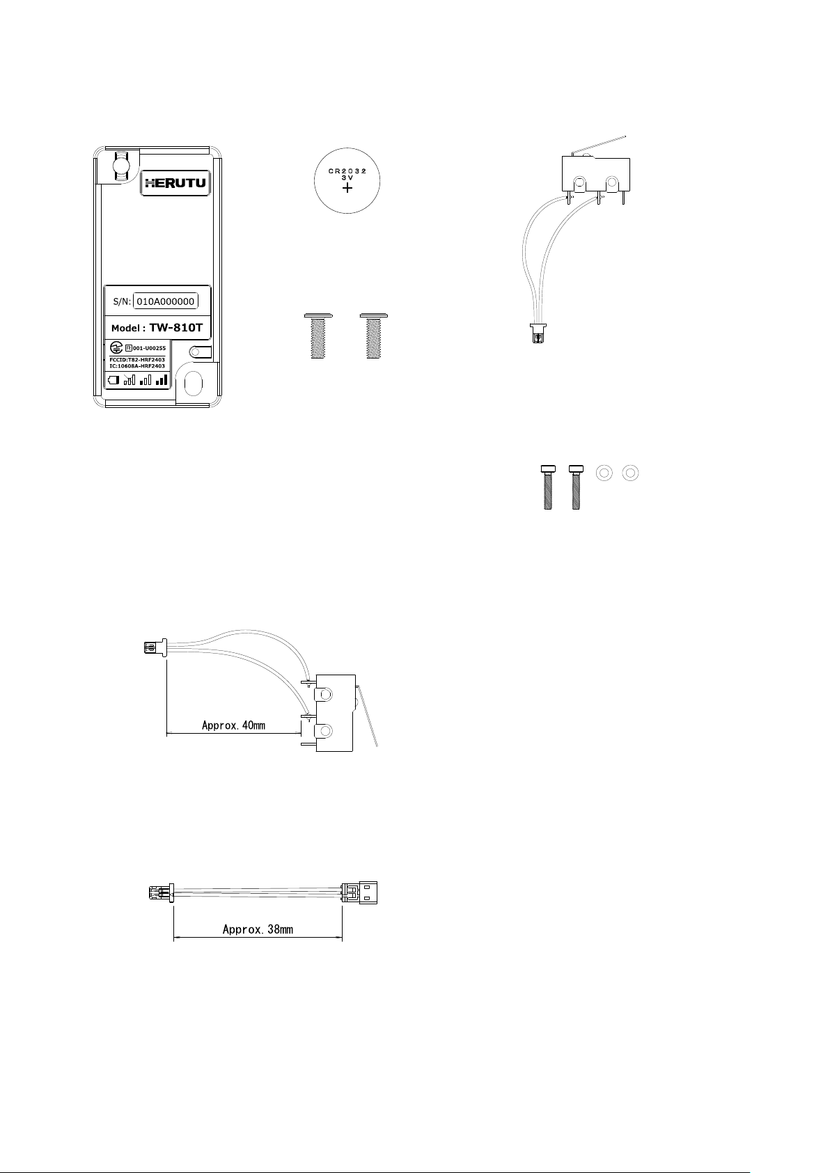
2.Main part and accessories
Transmitter TW-810T Coin battery CR 2032 Harness connector with limit switch
Base mounting screw
Slim head small screw M4xL12×2pcs
*Pre-attached to the transmitter.
Limit switch fixing bolt
Hex socket head cap bolt M2×L10×2pcs
Washer M2(φ2.2)×2pcs
Onerous option
Harness connector with limit switch TW810T-HCL (Purchase 10 pcs/lot.)
Conversion connector cable SHL-ZH-40 (Purchase 10 pcs/lot.)
For attachment of the transmitter to the tools currently using TW-800T without a harness connector
with limit switch.

TW-810T
3
3.Safety Precautions (Be Sure to Read This)
This section describes the matters to be observed in order to prevent harm to the users and other persons and
damages to the property.
■The following marks and displays classify and describe the extent of harm and damage caused by failing to observe
the display content and using this product wrongly.
This display column shows "a failure to do observe it could result in only the personal
injury or property damage".
■Handling this product
⚫This product is the wireless communication equipment made of precision parts. Do not
disassemble or modify it. Or the accident or fault may occur.
■Use and storage environment
⚫DO NOT USE OR STORE the product in the following places to prevent defects, malfunction,
deterioration, fire, and electric shock:
•Do not use and store it in places exposed to direct sunlight,
•Do not use and store it in places where liquids, foreign substances, corrosive gases or
combustible gases can enter the product,
•Do not use and store it in places with high humidity or where there is abundant oil smoke,
dust, sand, etc. ,
•Do not use it in an unstable place such as a wobbling table or an inclined plane,
•Do not use it in a place with vibration.
■Specific handling of this product
This product is a radio equipment with certification of construction design.
⚫It is prohibited by law to disassemble or modify certified devices.
⚫Do not remove the certification label affixed to the case. It is prohibited to use any product
without the label.
⚫This product is only available in the countries where the certification is acquired.
This display column shows "a failure to do observe it could result in death or
serious personal injury".
■Handling this product
⚫Do not use this product for application that requires the extremely high reliability affecting the
human life.
⚫Do not use this product in the area which the radio wave reaches or not.
■If a problem occurs during use
⚫When smoke comes or there is a strange smell, immediately stop usage and remove the power
plug from the outlet because it may cause fire and electric shock. Request the dealer or our
company to repair it.
!
Caution
!
Warning

TW-810T
4
■Notes on the Radio Law
○The wireless device used for this product is certified as a specific radio device for a radio equipment of a low power
data communication system based on the Radio Law. Therefore, a radio station license is not required to use this product.
○This product can be used only in Japan or countries where required certification is acquired. In the case that it is used
in other countries, this product may be damaged or it may damage other equipment. It also may conflict with the laws
of that country. Please contact our sales department for the countries that the product is certified other than Japan.
○Do not use this product near any person using cardiac pacemaker. The cardiac pacemaker may be disturbed by
electromagnetic wave, which may cause risk of life.
○Do not use this product near any medical equipment. The medical equipment may be disturbed by electromagnetic
wave, which may cause risk of life.
○Do not use this product near any microwave oven. Electromagnetic wave from microwave oven may disturb radio
communication.
○The wireless device of this product is certified under the Radio Law, so that DO NOT disassemble or remodel this
product.
■Notes on radio interference of 2.4 GHz radio
When communicating with 2.4 GHz band wireless products, pay attention to the following points.
In this product’s frequency band not only industrial, scientific and medical equipment such as microwave ovens but also
local radio stations for mobile objects identification (which require the license), specified low-power radio stations
(license not required), and amateur radio stations (license required) can be in operation.
○Before using this product, make sure that there are no local radio stations for mobile objects identification, specified
low-power radio stations and amateur radio stations operating nearby.
○In event that harmful interference occurs to any radio station by the radio wave from this product, stop using it
immediately and consult with us about avoiding interference.
○Also contact us in case of any trouble such as harmful radio interference to specified low-power radio stations for
mobile objects identification or amateur radio stations.
TW-810T
5
■FCC/IC Warning
Information about FCC Standard.
Contains FCC ID: T82-HRF2403
This device complies with part 15 of the FCC Rules.
Operation is subject to the following two conditions:
(1) This device may not cause harmful interference, and
(2) this device must accept any interference received, including interference that may cause undesired
operation.
FCC CAUTION
Changes or modifications not expressly approved by the party responsible for compliance could void the
user’s authority to operate the equipment.
This transmitter must not be co-located or operated in conjunction with any other antenna or transmitter.
This equipment complies with FCC radiation exposure limits set forth for an uncontrolled environment
and meets the FCC radio frequency (RF) Exposure Guidelines. This equipment has very low levels of
RF energy that is deemed to comply without maximum permissive exposure evaluation (MPE).
This equipment complies with FCC radiation exposure limits set forth for an uncontrolled environment
and meets the FCC radio frequency (RF) Exposure Guidelines. This equipment has very low levels of
RF energy that is deemed to comply without testing of specific absorption rate(SAR).
TW-810T
6
Information about ISED Standard.
Contains IC: 10608A-HRF2403
This device contains licence-exempt transmitter(s)/receiver(s) that comply with Innovation, Science and
Economic Development Canada’s licence-exempt RSS(s). Operation is subject to the following two
conditions:
(1) This device may not cause interference.
(2) This device must accept any interference, including interference that may cause undesired operation
of the device.
L’émetteur/récepteur exempt de licence contenu dans le présent appareil est conforme aux CNR
d’Innovation, Sciences et Développement économique Canada applicables aux appareils radio exempts
de licence. L’exploitation est autorisée aux deux conditions suivantes :
1) L’appareil ne doit pas produire de brouillage;
2) L’appareil doit accepter tout brouillage radioélectrique subi, même si le brouillage est susceptible d’en
compromettre le fonctionnement.
This equipment complies with ISED radiation exposure limits set forth for an uncontrolled environment
and meets RSS-102 of the ISED radio frequency (RF) Exposure rules. This equipment has very low
levels of RF energy that is deemed to comply without maximum permissive exposure evaluation (MPE).
Cet équipement est conforme aux limites d’exposition aux rayonnements énoncées pour un
environnement non contrôlé et respecte les règles d’exposition aux fréquences radioélectriques (RF)
CNR-102 de l’IC. Cet équipement émet une énergie RF très faible qui est considérée comme conforme
sans évaluation de l’exposition maximale autorisée (MPE).
This equipment complies with ISED radiation exposure limits set forth for an uncontrolled environment
and meets RSS-102 of the ISED radio frequency (RF) Exposure rules. This equipment has very low
levels of RF energy that is deemed to comply without testing of specific absorption rate (SAR).
Cet équipement est conforme aux limites d’exposition aux rayonnements énoncées pour un
environnement non contrôlé et respecte les règles d’exposition aux fréquences radioélectriques (RF)
CNR-102 de l’ISED. Cet équipement émet une énergie RF très faible qui est considérée comme
conforme sans évaluation du débit d’absorption spécifique (DAS).
This radio transmitter (10608A-HRF2403) identify the device by certification number or model number if
Category II) has been approved by Industry Canada to operate with the antenna types listed below with
the maximum permissible gain indicated. Antenna types not included in this list, having a gain greater
than the maximum gain indicated for that type, are strictly prohibited for use with this device.
Antenna type:1/4λ Monopole chip antenna Gain: Layout A 0.55dBi / Layout B 0dBi
Antenna type:1/2λ Dipole PIFA Gain: 0.9dBi
Antenna type:1/2λ Dipole antenna Gain: 2.0dBi
Le présent émetteur radio (10608A-HRF2403) a été approuvé par Innovation, Sciences et
Développement économique Canada pour fonctionner avec les types d'antenne énumérés ci dessous
et ayant un gain admissible maximal. Les types d'antenne non inclus dans cette liste, et dont le gain est
supérieur au gain maximal indiqué pour tout type figurant sur la liste, sont strictement interdits pour
l'exploitation de l'émetteur.
Type d’antenne:1/4λ Monopole chip antenna Gain: Layout A 0.55dBi / Layout B 0dBi
Type d’antenne:1/2λ Dipole PIFA Gain: 0.9dBi
Type d’antenne:1/2λ Dipole antenna Gain: 2dBi

TW-810T
7
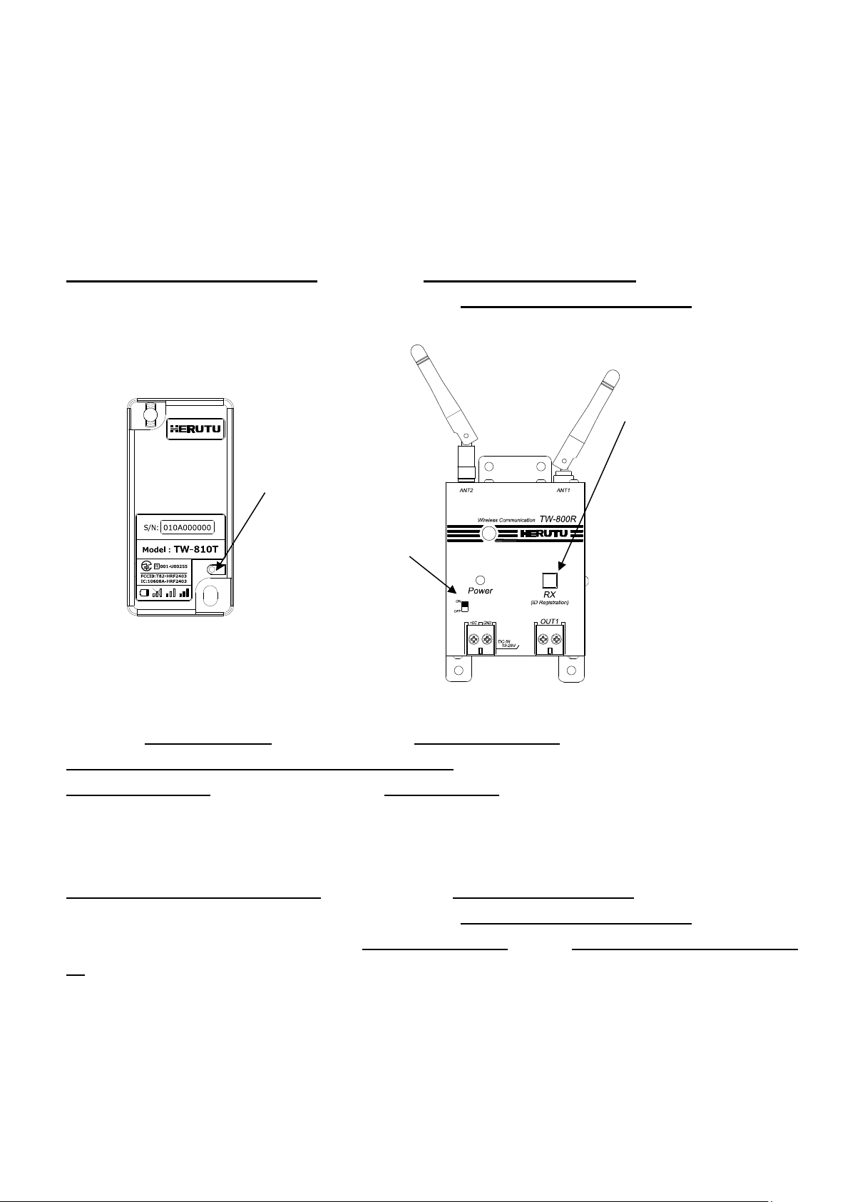
4.Name and Function of Each Part
①Main body case
Main body case. POM, a highly durable material, is used.
②Battery cap
Lid for fixing the coin battery (CR2032).
③Monitor LED
(green/red/yellow/orange)
An LED for communication confirmation/battery check. It lights up/blinks
green/red/yellow/orange according to the communication result.
④Test switch
(Pairing switch)
Used for testing wireless communication or for pairing.
⑤Harness connecting connector
Connector for connecting the supplied harness connector with limit
switch.
A wireless signal is transmitted by the work completion signal input (No-
voltage contact input) to the connector.
⑥Main body mounting hole
Mounting hole for fixing the main body to a Pokayoke tool. Two mounting
holes are provided. Use M4 screws to fix the main body.
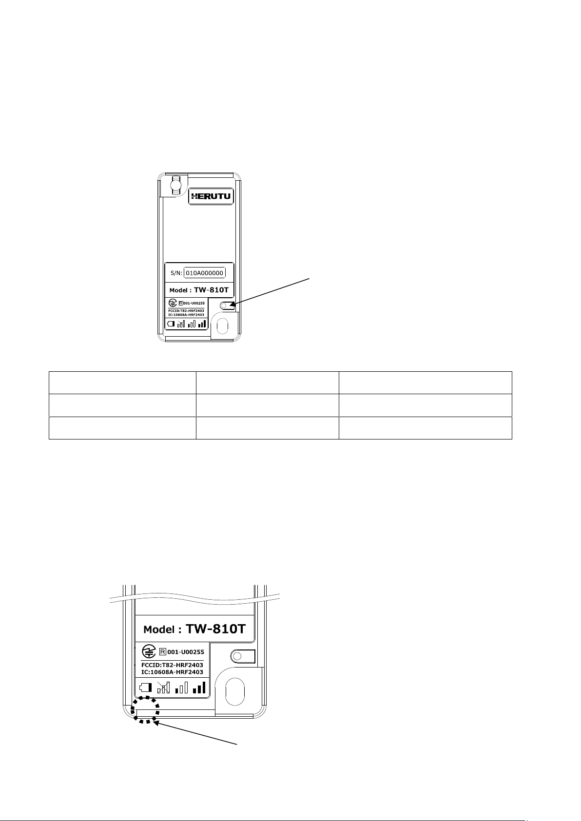
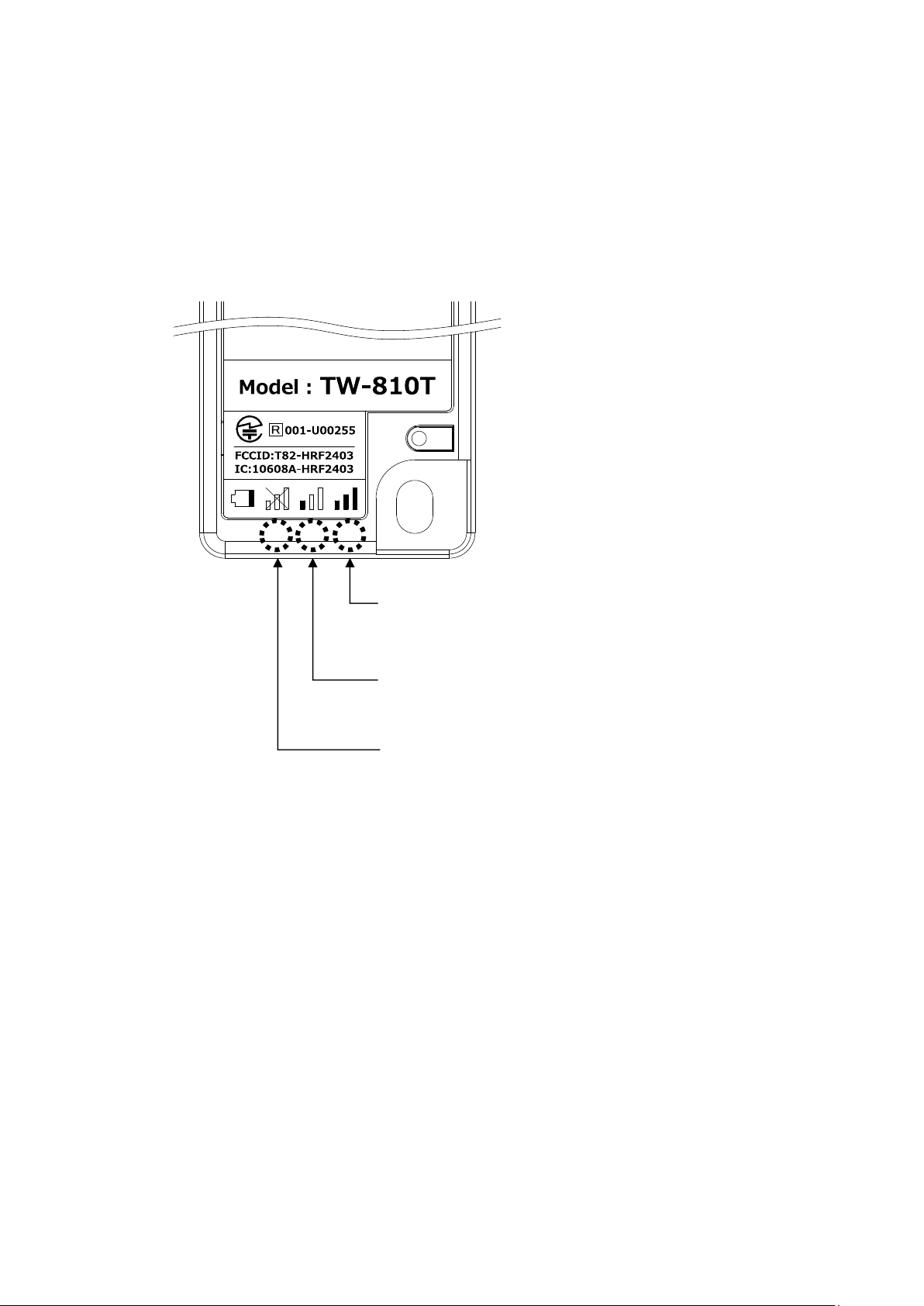
⑦Nameplate label
Nameplate label of the product. Model No. and serial No. are indicated on
the label.
Serial No. on the label represents the ID No. of the transmitter.

TW-810T
8
5.Attachment of TW-810T
<Attachment to torque wrenches>
①Attachment of the harness connector with limit switch
The harness connector is attached to the transmitter at factory. When it is removed for maintenance or
replacement, securely connect the harness connector with limit switch so that the black cable sits on the outer
side, as shown below.
The connector cannot be inserted in the wrong orientation.
②Attachment of the limit switch to the torque wrench base
Fix the limit switch to the wrench base by using the two supplied limit switch fixing bolts and flat washers.
When operating the torque wrench, make sure the movable range of the wrench lever matches the working
range of the switch.
◆The attention and the check method on limit switch attachment
When the lever working range of a torque wrench is small, a limit switch cannot be struck and a transmitter may
not send. In limit switch attachment, be careful enough and carry out.
It is recommended to check the attached condition of the limit switch by using a tester.
Wrench lever
The hex socket head cap bolt requires a washer.
Apply screw lock agent to the bottom 2 to 3 threads of the
hex socket head cap.

TW-810T
9
×
〇
③Attachment of the transmitter
To prevent the harness of the limit switch from getting caught in the case, limit switch or screw, use the mounting
holes of the main body case and fix the transmitter with the two supplied slim head small screws (M4 screws).
The harness is caught between the limit
switch, screws, etc. and the case.
TW-810T
10
<Input Judgment time for transmitter>
The transmitter is designed not to transmit signals when the signal input time from the limit switch is 40ms or
less. This prevents the transmitter from accidentally transmitting signals when dropping the torque wrench.
Due to the above mechanism, the transmitter may not transmit signals even after hitting the limit switch with
your finger, etc. for transmitting test signals.
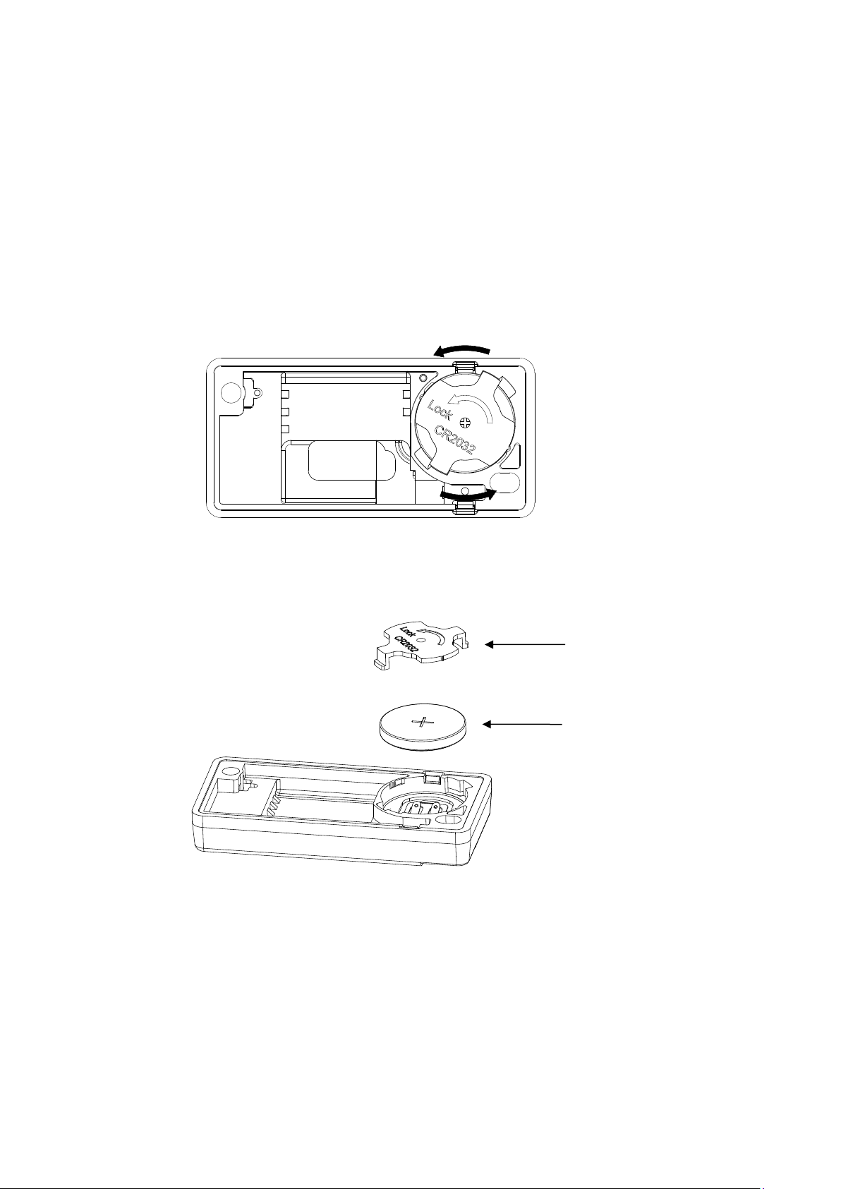
<Insertion or removal of the battery>
To close the battery cap, turn the battery cap securely in the direction of arrow shown below until it snaps into
place.
To remove the battery cap, turn the battery cap in the opposite direction from the arrow shown below.
When replacing the battery, be sure to insert the coin battery with the correct polarity.
Battery cap
Coin battery (CR 2032)
TW-810T
11
6.Setting
The transmitter and a Pokayoke receiver TW-800R-*** need to be paired before use.
By pairing them, they recognize an identification signal from each other and communicate with each other.
This manual describes how to pair the transmitter with the receiver TW-800R.
For pairing with a receiver other than TW-800R, see the instruction manual of each receiver.
⚫Pairing (registration)
①Press the lighting switch for paring of the receiver, and turn ON the power switch at the same time.
The lighting switch for paring blinks and the receiver enters the pairing mode for 10 seconds.
②Long press the pairing switch of the transmitter for 3 seconds or longer.
③The lighting switch for paring of the receiver goes out and pairing is complete.
④Turn OFF the power of the receiver once and turn it ON again, and the receiver can communicate with the
paired transmitter.
⚫Reset pairing
①Press the lighting switch for paring of the receiver, and turn ON the power switch at the same time.
The lighting switch for paring blinks and the receiver enters the pairing mode for 10 seconds.
Long press the lighting switch for paring for 2 seconds or longer, and the lighting switch for paring lights
up and the paired (registered) data of the transmitter is deleted.
◆Notes
A long press on the pairing switch of the transmitter (3 seconds or more) when the receiver is not in the pairing
mode resets the pairing with the receiver and prevents communication with the registered receiver. When pairing
is reset by mistake, perform the pairing procedure again.
Lighting switch for paring
Power switch
Pairing switch
(Test switch)
TW-810T
12
7.How to Use the transmitter
①Turn ON the power switch of the receiver.
Make sure the receiving LED is OFF.
When the receiving LED lights up, the transmitter is not paired. Pair the receiver and transmitter.
②A wireless signal is transmitted by turning the limit switch ON.
When wireless communication is normally executed, the receiver generates a relay output and the buzzer of the
receiver is activated according to the settings.
The green LED of the transmitter blinks once.
When the communication is not executed normally, the receiver is not activated.
The red LED of the transmitter blinks 10 times.
While the receiver is generating a relay output or preventing a double count, the receiver returns a BUSY signal
to the transmitter. Upon receiving the BUSY signal, the green LED of the transmitter blinks 4 times.
Transmitter
Receiver
Communication OK
Green LED blinks 1 time
Receiving LED blinks 1 time
Communication Failed
Red LED blinks 10 times
-
BUSY
Green LED blinks 4 times
-
The buzzer sounding time of the receiver is normally 100 msec. Only when the relay output time is set to 50
msec. and the double count prevention time is set to 10 msec., the buzzer sounding time is 50 msec.
*When an unpaired the transmitter transmits a signal, the red LED blinks 3 times.
Receiving LED (Green)
(Lighting switch for paring)
Monitor LED (green/red/yellow/orange)
TW-810T
13
●Test switch
The transmitter is equipped with a test switch for checking the communication status.
When the transmitter transmit the signal by test switch not limit switch, receiver doesn’t output relay output. But
LED of receiver only turns on.
The test switch also can be used as a pairing switch. A long press on the test switch (3 seconds or more) resets
the pairing with the receiver and prevents communication with the registered receiver. When pairing is reset by
mistake, perform the pairing procedure again.
Transmitter
Receiver
Communication check OK
Green LED blinks 1 time
Receiver(RX) LED blinks 1 time
Communication check Failed
Red LED blinks 10 times
-
●Battery level notification function
When the battery level becomes low and the battery needs to be replaced, the blinking green LED after signal
transmission turns into blinking orange.
When the orange LED blinks, please replace it with a new battery immediately.
When you replace the battery with a new one, the LED on the transmitter will return to green from the second and
subsequent transmissions.
Test switch
Press the round recess.
When the battery needs to be replaced, the blinking green LED
after signal transmission turns into blinking orange.
TW-810T
14
●Communication status notification
When your wireless communication is not good, the blinking green LED after signal transmission turns into
blinking yellow.
The transmitter can be used even when the yellow LED is blinking. However, there is higher possibility that
wireless communication will fail.
When the yellow LED is blinking, consider taking measures, such as “Improve the installed condition of the
receiver antenna”, “Remove obstructions between the transmitter and the receiver”.
When wireless communication is improved, the blinking yellow LED of the transmitter turns back to blinking green.
Green LED blinking: Communication OK
(Successful communication)
Yellow LED blinking: Communication OK
(Communication condition is not successful)
Red LED blinking: Communication Failed

TW-810T
15
8.Specifications
Item
Specifications
Compliance Standards
<Japan>
2.4GHz Low Power Data Communication System
Radio Equipment of Certification Regulation Article 2, Paragraph 1 Item 19
Radio Equipment Regulations Article 20 of 49 Paragraph 1
<USA> FCC Part.15-247
<Canada> ISED RSS-247 Issue 2
Radio format
F1D
Frequency Band
2,403MHz~2,478MHz
Number of Channels
76CH
Modulation Method
GFSK
Communication Method
Simplex
Antenna Power
2.1mW
Input(s)
1 No-voltage contact input
1 Test Switch
Display
4 LEDs
Communication status notification (Green/Yellow/Red), battery level
notification (Orange)
Power Source
1 Coin Battery (CR2032)
Operating Environment
Temperature: 0-50℃ (32-122℉)
Humidity: 80% or less (without condensation)
External Dimensions
(W x H x D)
32W×66H×10D mm (Excluding protrusions)
Weight
approx. 21g
Antenna
Inverse F-shaped sheet metal antenna
Battery Life
Approx. 900,000 uses (depending on usage conditions)

TW-810T
16
9.Dimensions Drawing

TW-810T
17
10.Before Determining Fault
Phenomenon
Cause and remedy
The transmitter does not transmit
LED does not light up
Battery capacity is low.
→Please replace the battery (CR2032).
The red LED blinks 3 times after transmitting.
Pairing is not done. (not registered)
→Perform pairing with the receiver to communicate with the
transmitter. (See P.11)
The red LED blinks 10 times after transmitting.
The power of the receiver is not ON.
→Make sure the power of the receiver to communicate with the
transmitter is ON.
The communication distance is too far.
→The distance is beyond the maximum communication distance
of the machine. Install the transmitter in a location where it can
communicate with a receiver.
The antenna installation status of the receiver is not good.
→Check whether or not the receiver’s antenna is surrounded by
obstacles blocking radio waves or placed in the control panel
(iron), and improve the installation status of the antenna. Also,
consider using an external antenna.
Communication cannot be done due to external factors.
→Use of a product using the same frequency band (2.4GHz
band) as this product may prevent communication. Please
contact our Sales Department with your product information.
The green LED blinks 4 times after transmitting.
The receiver is busy.
→ The receiver is generating a relay output or preventing a
double count.
For the settings, refer to the instruction manual of the receiver.
Pairing cannot be done
The receiver is not in the pairing mode.
→Set the receiver to the pairing mode and press the pairing
switch of the transmitter for 3 seconds or more. (See P.11)
Table of contents
Other Herutu Transmitter manuals


