Herutu TW-510T User manual

Wireless equipment for Torque wrench Transmitter
TW-510T
Instruction Manual V2.50
Please use this Instruction manual correctly on reading well.
Please keep it carefully to be able to read immediately, when required.


To use this product in safety and comfort, (Be sure toread)
Thank you very much for purchasing our product.
This operation manual contains the precautions necessary for preventing an accident caused by the
use in an improper ways.
Read it carefully while thoroughly understanding the meanings of pictorial symbols.
Using in an improper way while ignoring this pictorial symbol might
cause a serious human injury.
Using in an improper way while ignoring this pictorial symbol might cause
a human injury or physical damage.
■The type of precautions that should be observed, are classified using the following pictorial
symbols.
This pictorial symbol indicates a “Reminder” to attract an attention.
This pictorial symbol indicates a “Prohibition” to prohibit a certain action.
■For the usage to be commonly applied in all the models:
●Avoid using in a place with a plenty of humidity or dust. Otherwise, absorbing a dust
or water contents may cause machine trouble, fire or electrical shock.
■For handling this machine:
●This is the electronic devise or wireless radios composed of the precision parts.
Do not overhaul/remodel. It may cause accident or machine trouble.
!Warning
!Caution
!
ty
uu
i
!Caution
■For handling this machine:
●Do not use this product for the application needing the high reliability
related to human lives.
●Do not use this product in a place where it is uncertain about whether or
not radio waves reach.
■For handling the power source:
Be sure to observe the following precautions to prevent the AC adapter and Power cord
from being heated, damaged or ignited.
●Do not approximate theAC adapter and Power cord to a fire, or do not put
them into a fire. The AC adapter and Power cord can be broken or ignited,
resulting in an accident.
●You can use theAC adapter and main body only with the specified power
voltage to protect them from the damage and fire accident.
●Do not use theAC adapter and main body in a wettable atmosphere.
It may cause accidents or troubles such as heating, igniting or electrical shock.
●Do not touch theAC adapter, main body, Power cord and Plug outlet with
wet hands. It may cause an electrical shock.
●Do not damage the Power cord.
A short-circuit or heating may cause a fire or electrical shock.
●Do not use the Power plug with dust being adhered.
A short-circuit or heating may cause a fire or electrical shock.
●Do not give a strong impact onto the AC adapter.
It may cause an accident or machine failure.
●If you find out deformedAC adapter, do not use it.
It may cause an accident or machine failure.
●do not use this product in a place where flammable gas can be generated.
It may cause a fire accident.
●Never overhaul theAC adapter.
It may cause an accident or machine failure.
■When trouble happens during use:
Since it may cause a fire or electrical accident, disconnect a power plug, and
immediately ask outlet store or our company torepair.
●When smoke or abnormal odors are generated, stop using, immediately
disconnect a power plug, and ask outlet store or our company torepair.
●Once the Power cord is damaged, do not use it.
Using it as is may cause a fire or electrical accident.
This operation manual is translated a product for Japan into English/
This product is based on Japanese Wireless law.
!
!Warning

Descriptions of Product number label
Model
Product number
Logo mark
Transmit frequency ID No.
R2:259.55MHz Stamped when set before shipped
R4:259.65MHz

Contents
1.General descriptions............................................................................................................ 1
1-1.Features........................................................................................................................ 1
2.Specifications ...................................................................................................................... 2
3.Name of each section.......................................................................................................... 3
4.Dimensional drawing........................................................................................................... 5
5.To install on the Torque wrench........................................................................................... 6
5-1.Preparation for installation............................................................................................ 6
5-2.Installation..................................................................................................................... 8
6.To change the ID setting.....................................................................................................11
6-1.Displaying method of ID ..............................................................................................11
6-2.To change the ID setting............................................................................................. 12
7.Operation methods............................................................................................................ 13
7-1.To test the Transmitter................................................................................................ 13
7-2.Operating timing......................................................................................................... 14
7-3.To replace the battery................................................................................................. 15
8.Precautions during use...................................................................................................... 17
9.Troubleshooting................................................................................................................. 18
10.Warranty.......................................................................................................................... 19
11.Option .............................................................................................................................. 22
Appendix ID Setting list ........................................................................................................ 23

1
1.General descriptions
1.General descriptions
Thank you very much for purchasing the Wireless Equipment for Torque Wrench
Transmitter TW-510T”.
This operation manual contains the instructions necessary for using the “TOBISHIME
Transmitter TW-510T” (hereinafter specified as “TW-510T”). Thoroughly read through this
manual before use to correctly operate.
Once the TW-510T is mounted on the Torque wrench with Limit switch (LS), the
tightening completion signal of Torque wrench can be transmitted to each series of our
TW-510R.
This high capacity Radio Transmitter running through the weak radio wave of 260MHz
zone provides the noise-proof and reliable system.
1-1.Features
●This machine is designed as the successor device to the TW-200T, intended
for miniaturizing the overall dimensions.
●The Torque wrench with Limit Switch (LS) currently being used can be easily
remodeled into the wireless type.
●This Transmitter consists of compact design using the coin battery type power
supply.
●License and qualification for radio unwanted.
●Noiseless weak radio wave of 260MHz-zone is used.
●The antenna-built-in type is superior in handling (controllability).
●The ABS resin case mounted enables the dust & oil mist proof.
●The 8-bit code can be set so that multiple units can be used.

2
2.Specifications
2.Specifications
Items
Specification
Remarks
Frequency
259.55MHz
R2 *1
259.65MHz
R4 *1
Intensity of
radio wave
Electric intensity at 3m distance is 500μV/m or less
Weak radio wave
Modulation
method
Binary FSK by the direct modulation
Transmission
method
Unidirectional transmission
Transmit data
14-bit/1-frame
Approximate 7-9frame transmission
1-shot
Input
Limit SW×1
SS-01GL(Omron)
Test SW×1
Communication
distance
Approximate 10m in radius
*2
Guarantee of
working
temperature
0-50℃
Power supply
Coin battery CR2032(3V)
Battery life
Approximate 250,000-shot
Measured at
interval of 1sec
1-shot time
Approximate 300mS
Antenna
Mounted in case
ID setting
8-bit Dip SW
Display
Battery check display LED
External size
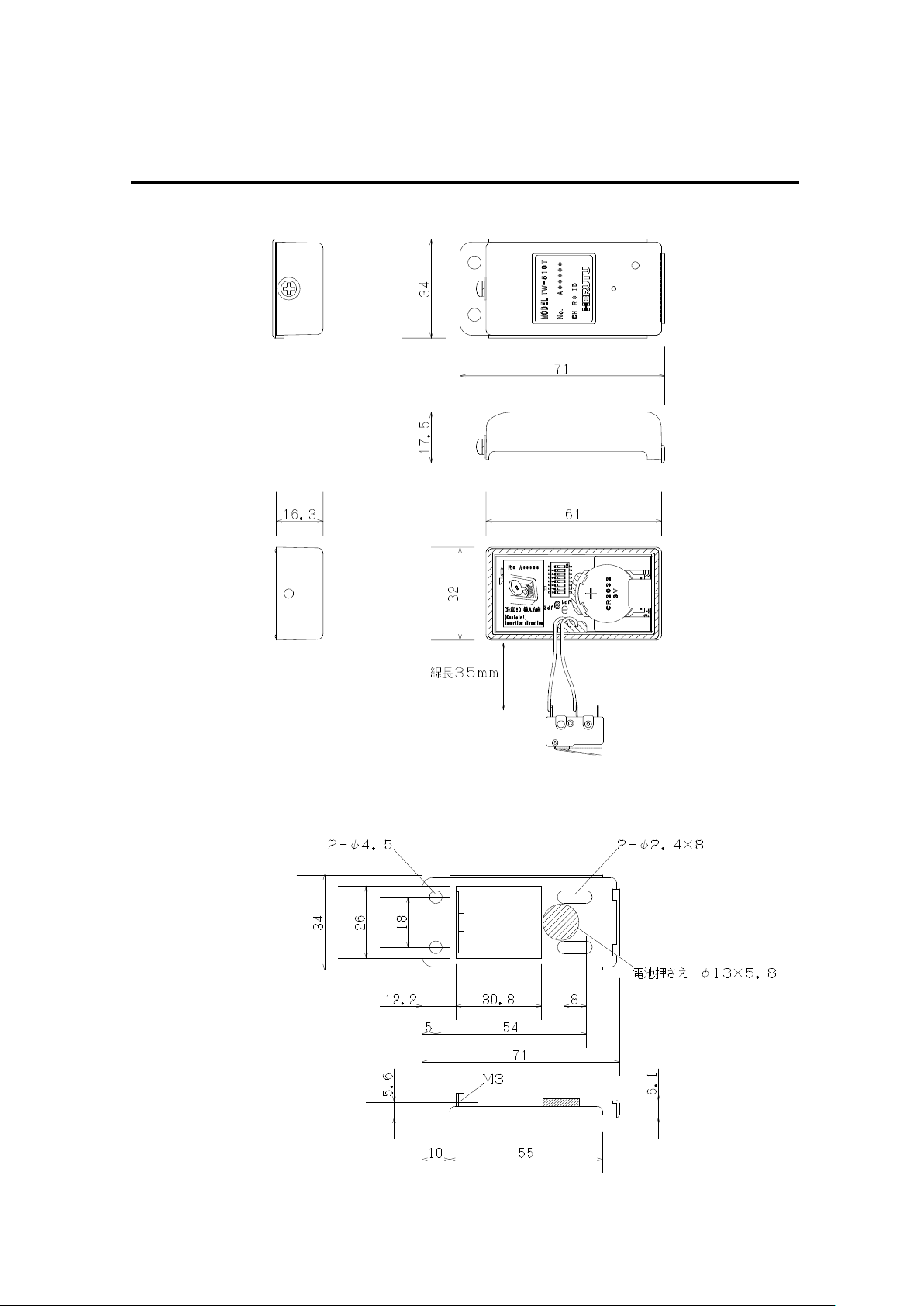
34×71×17.5mm
See drawing.
Weight
40g
(Seat, Limit SW and battery are included)
*1:Use either R2 or R4 frequency. (Stated on product number label)
*2:It may sometime disable the communication at the place with a lot of radiation noise
emitted from an electrical welding equipment.
It is possible to interrupt communication at the dead point where a reflected
electric wave interferes. We recommend you to use Diversity type receiver
(TW-510RD) in such a case.

3
3.Name of each section
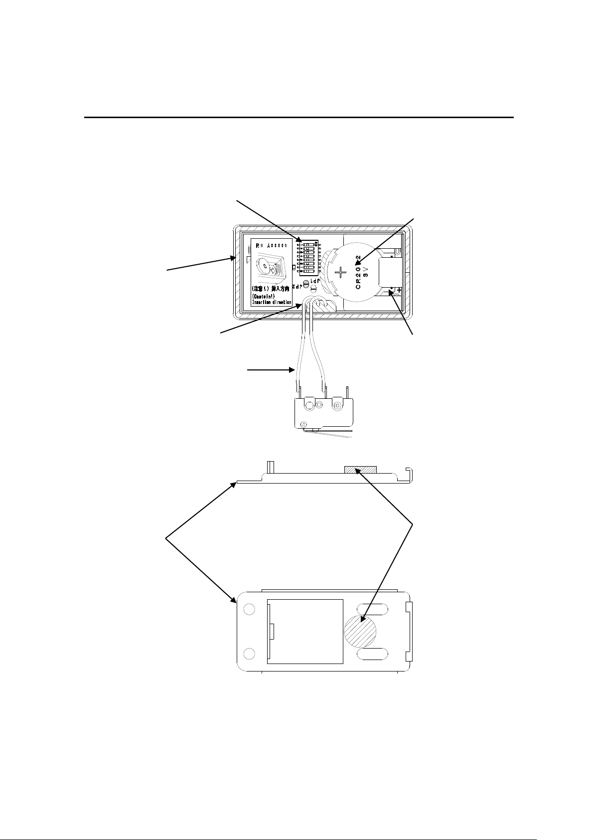
3.Name of each section
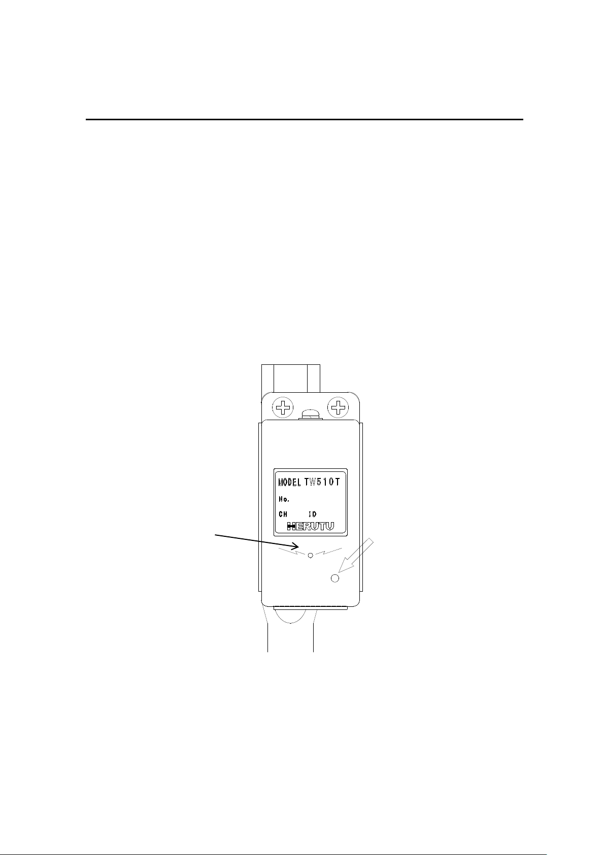
TEST SW
Battery check windows
Fixing screw
Case fixing screw
Product No label
4
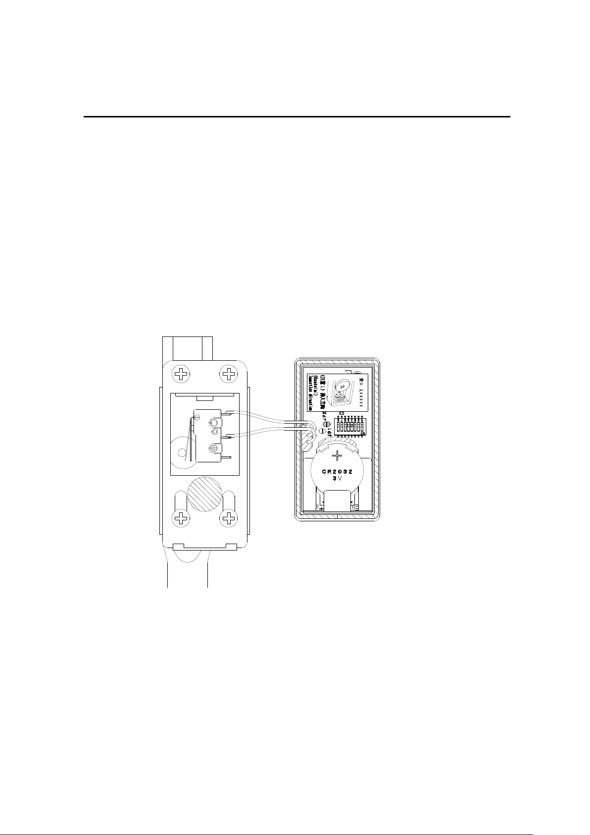
3.Name of each section
Battery CR2032
Silicon caulking for fixing board
Battery case
Limit SW(SS-01GL)
DIP SW for ID setting
Packing
Battery holder
Seat
5
4.Dimensional drawing
4.Dimensional drawing

6
5.To install on the Torque wrench
5.To install on the Torque wrench
5-1.Preparation for installation
1)Check the parts necessary for installation.
Torque wrench with Limit SW(LS) (User shall prepare)
Note)Depending on the type of Torque wrench, transmitter may not be installed. Contact our sales office.
Transmitter and a set of accessories
Seat ×1
(with Battery holder)Transmitter body×1
(with Limit SW)
Battery×1 Fixing screw×4 Hex screw×2
CR2032(3V) (M4*L5) (M2*L10)
2)Tools necessary for installation
・Allen wrench :Size 1.5mm
・Phillips screwdriver :Size #2
・Screw locking agent
・Prick punch (sharp edge)
Set Screw×1

7
5.To install on the Torque wrench
3)Remove the Cover and Limit SW.
2.Remove two hexagon socket head
bolts, and remove the Limit SW.
1.Remove four fixing screws, and remove the cover.
Because the limit SW mounted with Torque wrench as standard has the different current
capacity, do not use it.
Weld bead
3.Verify that the Seat of Torque wrench is flat.
If the weld bead is protruded from the Seat, grind it.

8
5.To install on the Torque wrench
5-2.Installation
1)To install the Seat
-Fix the Seat with four fixing screws.
-For the application with heavy oil mist, fill up the caulking agent between
Wrench seat and Seat and also between Wrench shaft and Wrench seat to protect the
internal board.
Apply the screw locking
agent onto the 2 to 3 threads
of screw edge.
2)For ID setting
-See the next article(6. To change ID).
3)-Fix the Transmitter Limit SW with two hexagon socket head bolts(which was
removed).
-Verify that the moving range of wrench lever is well suited for the movement
range of switch during the wrench in movement.
The hexagon socket head bolt requires a washer.
Apply the screw locking agent on 2 to 3
threads of hexagon socket head bolt.
Wrench lever

9
5.To install on the Torque wrench
4)Hook the Transmitter on the Case holder of Seat, set it with an attention being
paid not to bite the cord, and fix it with the set screw as firmly pushing the case.
Case holder
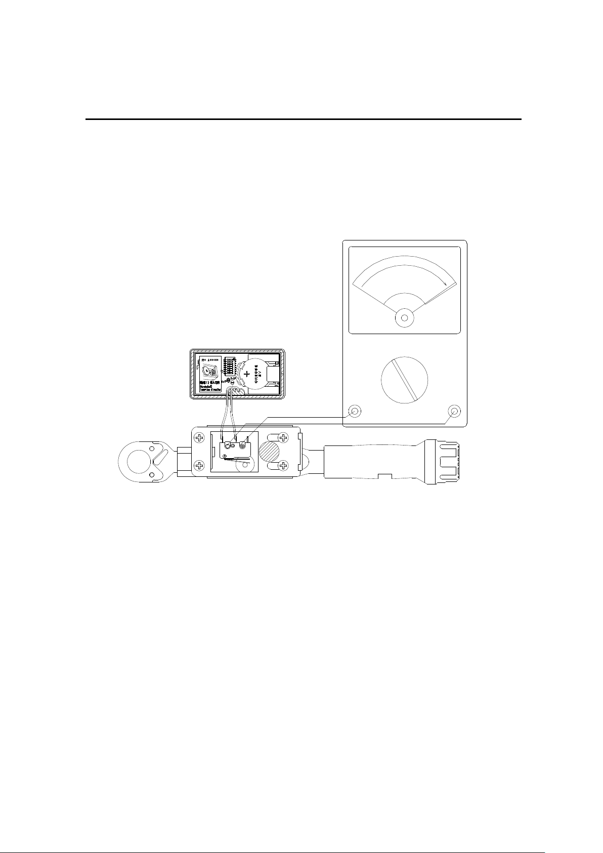
<Installation and confirmation method of Limit switch>
When the lever movement reach of the torque spanner is small, it isn't possible to hit limit
switch, and a transmitter doesn't send. Please be careful sufficiently in case of a limit
switch installation. We'll recommend to install it using testers and confirm the state as
follows.
1. A wrench is made an adjustment to the use Newton value
2. The limit switch is tacked in a wrench.
3. The connector of wrench socket is set on the vice table or to fix it in order to
turn the bolt. Please be careful sufficiently not to be broken the wrench.
4. Limit switch is connected with a tester.(+)(-) is as follows.
5. A limit switch of a wrench moves a wrench to the done location and fixes
hexagon socket head cap bolt by the location a limit switch enters certainly.
A wrench has a roughly 2 sets of mounting hole, and the person who arrives
obediently is chosen. Hexagon socket head cap bolt is M2 and a mounting
hole of a limit switch is φ 2.35, so it's adjusted by slanting having for this
difference. Please bend and don't adjust a lever. When the torque did the
location of the lever, it's adjusted at the location which isn't forced more than
level.
10
5.To install on the Torque wrench
6. It's confirmed whether it receives in its state and normally outputs.
It's confirmed once again whether the lever location isn't forced too much.
7.A case of TW-510T is covered, and it's confirmed whether a receiver
normally receives.

11
6.To change the ID setting
6.To change the ID setting
6-1.Displaying method of ID
The ID is normally addressed in decimal notation, however, for setting, convert it into
binary notation and set it with the DIP Switch.
The following figure shows the case where each bit of DIP switch is set in decimal
notation.
Example of setting:ID 5
Bit Bit weight Decimal number
120=1
221=2
322=4
423=8
524=16
625=32
726=64 Add “ON bit”.
827=128 e.g.:If “1” and “3” are ON,1+4=5
The examples of ID setting are shown below.
ID 01234
・・・・・・・・
ID 56・・・・・・・・ 254 255
The 8-bit ID includes 256-type ranging from 0 to 255.
ON
8 7 6 5 4 3 2 1
12
6.To change the ID setting
6-2.To change the ID setting
Pull out the fixing screw of Transmitter, and disassemble the main body from the
Seat.
Change the ID of Transmitter according to the Display stated in previous page.
Verify that Receiver is set in the same contents as well.
Set the lever of Dip Switch using the sharp edge like Prick punch.
The Dip Switch can be easily damaged. Do not apply an excessive
force during setting.
Test the transmission before assembling to
check that Receiver is consistent with the ID number.
Upon completion of setting, install the Transmitter according to “5-2 Installation”
with an attention being paid not to bite the cord.
13
7.Operational methods
7.Operation methods
7-1.To test the Transmitter
・Push the Test switch of Transmitter using the edge of ball-point pen.
(LED is lit on Battery check window and data for one shot is transmitted.)
・Verify the Transmitter for LED lighting conditions through the Battery check
window.
・If LED blinks or does not light on during Test switch being pressed, replace
the battery (CR2032).
・The battery should be checked not only before operation but also after use.
・Checking the operation(Output, Buzzer sound) of Receiver allows you to
confirm the communication status.
Check LED for lighting.
Push here with the ball-point-pen.

14
7.Operational methods
7-2.Operating timing
・The following figure shows the operating timing of Limit switch/Transmitter.
Limit switch:
Set the Limit switch ON time at 10mS or over.
Keep 10mS or over in shot interval.
350mS or over(*1)
Transmitter
Electric wave is emitted for about 300mS.
・The TW-510 model enables the transmission at the interval of 350mS or over.
*1 This interval time should be more than the double counting prevention
time of Receiver.
The Receiver has the double count prevention function to avoid the double
counting.
For detail of double counting prevention time, see the operation manual of
each receiver.
Table of contents
Other Herutu Transmitter manuals


Popular Transmitter manuals by other brands

Selve
Selve Commeo Transmit Operating instruction

Siemens
Siemens SITRANS LR260 operating instructions

Minicom
Minicom CAT5 VGA/DATA Transmitter installation guide

Phonak
Phonak inspiro user guide

YOKOGAWA
YOKOGAWA Dpharp vigilantplant EJA210A user manual

Yamamoto Electric Works
Yamamoto Electric Works Manostar EMT1 instruction manual


