manuals.online logo
Brands
  1. Home
  2. •
  3. Brands
  4. •
  5. Herz
  6. •
  7. Thermostat
  8. •
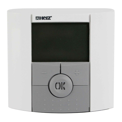
  9. Herz H7714 Series Operating manual

Herz H7714 Series Operating manual

1/
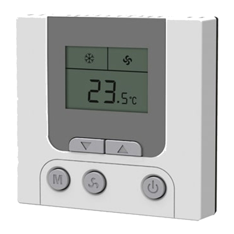
H7714 DA/DB-TL FCU THERMOSTAT
4
H7714 series thermostats are suitable for industrial, commercial, and room
temperature control, which is applied to the 3-speed fan, DC 0-10V for the
electric control
H7714 Series Thermostat User and Installation Manual
valve.
H7714-MD(with Modbus) model is used to realize remote centralized control
and management, especially for office buildings, apartments, hotels, and other
commercial buildings.
Model Selection Guide
H7714 DA/DB
DA/DB: 2-Pipe
–T L
Coil
FCV2: 4-Pipe Coil
V: Only Analog Output
White Backlight
7 Day/4 Period Schedule
Characteristics and Advantages
Characteristics Advantages
Product serialization This series of products have a variety of functional combinations,
which can be suitable for different application requirements
Large Size LCD Screen White back-light, clear display
EEPROM Memory Auto-recovery after power failure
ABS+PC Plastic Cover and Base Strong and durable Intrinsically flame retardant
Heavy Duty Relay Available 7A relay optional for high static pressure FCU
Function
Application: 2-Pipe/4-Pipe Fan Coil Control
Operation Mode: Cooling/Heating/Ventilation
Display: Operation Mode, Room temperature, Fan
speed, Valve Status, Clock, ECO mode
Room Temperature Setting
Backlight: White
Fan Control: 3-Speed, Manual/Automatic
Valve Control: AO 0~10VDC modulating
Timer: Time on/off or 7 day/4 period
programmable schedule
Key Lock
Temperature Setpoint limit
Auto-restart after power failure
Low-temperature protection
External Input: Remote temperature sensor and
digital switch (Hotel keycard)
Technical specifications
Power supply: 24VAC ±10%, 50/60Hz
Power consumption: ˂ 2 W
Temperature setpoint range: 5 ~ 35 ℃in 0.5 ℃
increments
Temperature measurement range: 0 ~ 55 ℃
Accuracy: ±1 ℃
Built-in Temperature Sensor Type: 10K NTC
Remote Temperature Sensor Type: 10K NTC
Terminations: Screw terminals block
Relay Capacity: 5A (Res.) at 250 Vac (Maximum),
7A Relay optional
Modulating Output: 0~10VDC Proportional
Housing Material: PC + ABS plastic
Operation Ambient Condition: 0 ~ 45℃, 90% RH
Non-condensing
Storage Ambient Condition: -10 ~ 60℃, 90% RH
Non-condensing
Dimensions: 86×86×15.5 mm (W×H×L)
Protection class: IP20
Basic Function Setting
Operation Key Setting
Turn On/Off Turn On / Turn Off
Operation Mode M (Cooling), (Heating), ( Air venting)
Temperature Setting ˄˅Room Temperature Setpoint
Fan Speed (Low), (Medium), (High), AUTO
2/
H7714 DA/DB-TL FCU THERMOSTAT
4
Time Setting
Turn on the thermostat and keep the power supply, press and hold the “M” key for 5 seconds, the “hh” icon will
flash on the Thermostat screen, press the “M” key repeatedly, the “hh-mm-week” icon will flash cyclically, and
press the “˄” or “˅” key to adjust the Hour, Minute and days of the week.
Basic Parameters Setting
Turn off the thermostat and press and hold the "M" key for 6 seconds to log in to the parameter setting menu,
press the "M" key to switch parameter items, and press the “˄” or “˅” key to adjust the parameter settings.
Code Parameters Default Setting Range
Addr 00 Thermostat address 00 01 ~ 250
(Only for H7714 with Modbus)
Lrch 01 Reserved 00 N/A
PiPE 02 2 Pipe / 4 Pipe 02 02: 2 Pipe; 04: 4 Pipe
dAb 03 DA / DB db da: DA db: DB
bc 04 Built-in sensor calibration 00
-5℃ ~+5℃
bd 05 Dead band 1℃ Setting range: 1 ~5℃
uP 06 Upper limit of Temp. setting 35℃ Setting range: 7℃ ~ 35℃
dn 07 Lower limit of Temp. setting 5℃ Setting range: 5℃ ~ 33℃
Lo 08 Low Temp. protection setting 5℃ Setting range: 5℃ ~ 17℃
LoEn 09 Low Temp. protection 00 00: Disable 01: Enable
Pon 10 Restart after power failure 00 00: Off 01: On 02: keep the last status
cLoc 11 Timer and programmable
schedule 01 00: Disable 01: Timer on/off only for one time
02: Timer on/off for every day 03: 7 day/4 period schedule
Loc 12 Key Lock 00 00: Disable 01: Enable
SEn 13 Temperature Sensor selection 00 00: Built-in Sensor 01: Remote sensor
bc 14 Remote sensor calibration 00 -5℃ ~ +5℃
Pir 15 Signal output interval time 10 10:10s, setting range: 10 ~ 300
Pin 16 Reserved 00 N/A
PiP 17 PI Minimum Signal 03 Setting range: 1~10, if the room temperature is higher than the
setpoint by more than 3 ℃, the output signal will be 10
Pii 18 KI 01 00 ~ 99, 0.04V/bit, 1 by step
PIC 19 Control signal type 00 00: PID, Auto output;01: Non-PID, manual output
Pid 20 Output signal Direction 00 00: 10V On 01:10V Off
Out 21 Output signal Proportion by
Manual 255 when PID 20 is 0, 0 ~ 255 stands for 0 ~10v
when PID 20 is 1, 0 ~ 255 stands for 10 ~ 0v
InP 22 Hotel Card (Terminal D1&D2) 00
00: Disable
01: When "D1"and "D2/G"are connected, the thermostat will
turn on. When "D1"and "D2/G"are disconnected, the thermostat
will turn off.
02: When "D1"and "D2/G"are connected, the thermostat will
turn off. When "D1"and "D2/G"are disconnected, the
thermostat will turn on.
03: When "D1"and "D2/G"are connected, the thermostat enters
the ECO mode, and when "D1"and "D2/G"are disconnected, the
thermostat will exit ECO mode.
04: When "D1" and "D2/G" are connected, the thermostat exits
the ECO mode, and when "D1"and "D2/G"are disconnected,
the thermostat will enter the ECO mode.
Coo 23 Cooling setpoint for ECO mode 28 Setting range: 22 ~ 32℃.
HEA 24 Heating setpoint for ECO mode 16 Setting range: 10 ~ 21℃.
bPs 25 Baud Setting 00 00: 4800bps 01:9600bps
CHE 26 Parity Bite 01 00: No 01: Odd 02: Even
vEr 27 Firmware Version 10 V1.0
dEF 28 Restore to factory setting 00 00: Disable 01: Enable
(Only for H7714 with Modbus)
3/
H7714 DA/DB-TL FCU THERMOSTAT
4
Timer on/off and 7 days / 4 Period Schedule
Timer on/off: The timer on/off function can be set to single or daily repeat. (The parameter item "Pon 11"
should be set to "01" or "02").
Turn on the thermostat, press and hold the “ ” key for 5 seconds to enter the timer parameter setting menu
Press the "M" key repeatedly to switch the parameter options of “Timer on” and “Timer off” status, and
press the “˄” or “˅” key to set the time parameters (hours and minutes) of the “Timer on” and “Timer off”.
Wait 10 seconds after setting and the thermostat will automatically save the settings and exit the settings
menu.
Schedule: The schedule function can provide programmable management of room temperature for four time
periods a day and seven days a week. (The parameter item "Pon 11" should be set to "03").
Turn on the thermostat, press and hold the "M" and " " keys for 5 seconds to enter the schedule setting
menu. Press the "M" key to switch the following parameter items, and press the “˄” or “˅” key to adjust the
parameters in sequence.
♦Day of the week (Mon / Tues / Wed / Thu / Fri / Sat / Sun)
♦Period of daily (1 ~ 4)
♦The beginning hour of the period (0~23)
♦The beginning minute of the period (0~59)
♦The temperature setpoint of the period
Wait 10 seconds after setting, the thermostat will automatically save the settings and exit the setting menu.
Parameter Description:
DA/DB description
DA: When the room temperature reaches the setpoint, the valve will be closed and the fan keep running.
DB: When the room temperature reaches the setpoint, both the valve and the fan will be closed together.
Low-temperature protection function: When the room temperature is below 5°C, the thermostat
automatically turns on the heating operation and the " " icon will be displayed on the screen. When the
room temperature rises to 7°C, the thermostat automatically turns off the heating operation.
Hotel card function: adjust the setting of item "InP 22" in the parameter table, the setting range is 00 ~ 04.
00 Disabled
01 When "D1"and "D2/G"are connected, the thermostat will turn on. When "D1"and "D2/G"are disconnected,
the thermostat will turn off. The thermostat " " key not working.
02 When "D1"and "D2/G"are connected, the thermostat will turn off. When "D1"and "D2/G"are disconnected,
the thermostat will turn on. The thermostat " " key not working.
03 03: When "D1"and "D2/G"are connected, the thermostat enters the ECO mode, and the " " icon is
displayed on the thermostat screen. When "D1"and "D2/G"are disconnected, the thermostat will exit ECO
mode and the " " icon will disappear. In ECO mode, the thermostat will automatically run the fan at low
speed according to the setting of the "Coo 23" and "HEA 24" items, and the user cannot manually adjust the
thermostat settings.
04 04: When "D1"and "D2/G"are connected, the thermostat exits the ECO mode, and the " " icon will
disappear. When "D1"and "D2/G"are disconnected, the thermostat will enter the ECO mode, and the “ ”
icon will be displayed on the thermostat screen. In ECO mode, the thermostat will automatically run the fan
at low speed according to the setting of the "Coo 23" and "HEA 24" items, and the user cannot manually
adjust the thermostat settings.
Note: When the "Inp 22" item Setting is “01” or “02”, the "cLoc 11" timer function and "Pon 10" restart
function are invalid.
Day of week
Period 1 Period 2 Period 3 Period 4
Time / Setpoint Time / Setpoint Time / Setpoint Time / Setpoint
Mon 6:00 / 24℃ 10:00 / 26℃ 16:00 / 24℃ 22:00 / 25℃
Tue 6:00 / 24℃ 10:00 / 26℃ 16:00 / 24℃ 22:00 / 25℃
Wed 6:00 / 24℃ 10:00 / 26℃ 16:00 / 24℃ 22:00 / 25℃
Thu 6:00 / 24℃ 10:00 / 26℃ 16:00 / 24℃ 22:00 / 25℃
Fri 6:00 / 24℃ 10:00 / 26℃ 16:00 / 24℃ 23:00 / 25℃
Sat 7:00 / 24℃ 10:00 / 24℃ 16:00 / 24℃ 23:00 / 25℃
Sun 7:00 / 24℃ 10:00 / 24℃ 16:00 / 24℃ 22:00 / 25℃
4/
H7714 DA/DB-TL FCU THERMOSTAT
4
Key lock function
Key lock: Turn off the thermostat, press and hold the "M" key for 6 seconds to enter the parameter menu,
and adjust the "Loc 12" item to 01 to enable the key lock function. In key lock mode, the icon “ ” will be
displayed on the thermostat screen, and all thermostat keys will not work.
Key unlock: Press and hold the “˄” or “˅” keys for 6 seconds, the thermostat will enter the temporary
unlock mode, and the icon " " will disappear. If no key is pressed for 30 seconds, the thermostat will enter
the lock mode again.
Alarm Code Description
Code Description
E1 Temperature sensor short circuit warning, valve and fan will stop operation
E2 Temperature sensor open circuit warning, valve and fan will stop operation
HI High temperature warning. If the room temperature is >55°C (131°F)
LO Low temperature warning. If the room temperature is <0°C (32°F).
EE EEPROM Error
Wiring Diagram
Fan 85~260 VAC
50/60Hz
H7714 DA/DB-TL
D1
AO1
D2/G
Low
Med
Hi
R
L
S2/G
S1
Remote
Sensor Remote Switch
Valve
24 VAC
COM
L
N
TR
C
TR
24 VAC
COM
85~260 VAC
50/60Hz
H7714 V-TL
D1
AO1
D2/G
R
L
S2/G
S1
Remote
Sensor Remote Switch
Actuator
24 VAC
COM
L
N
TR
C
TR
24 VAC
COM
Fan 85~260 VAC
50/60Hz
H7714 FCV2-TL
D1
AO1
D2/G
Low
Med
Hi
R
L
S2/G
S1
Remote
Sensor Remote Switch
Val 1
24 VAC
COM
L
N
TR
C
TR
24 VAC
COM
Val 2
AO2
Note:Please follow the wiring diagram correctly. Do not
let water, soil and other debris enter the thermostat,
otherwise, it will damage the thermostat.
Terminal Description
R
Power Supply 24VAC ±10%,50/60Hz
C
L Live Wire, AC230V
Hi
Fan Control
High Speed
Med Medium Speed
Low Low Speed
AO1 Analog Output
(0~10 VDC)
Valve 1 Control (Heating
valve when FCV2 model)
AO2 Valve 2 Control (Cooling
valve when FCV2 model)
D1 External Dry
Contact
Remote Switch or Hotel
Keycard
D2/G
S1 External Input External Temperature
Sensor (NTC 10K)
S2

Other Herz Thermostat manuals

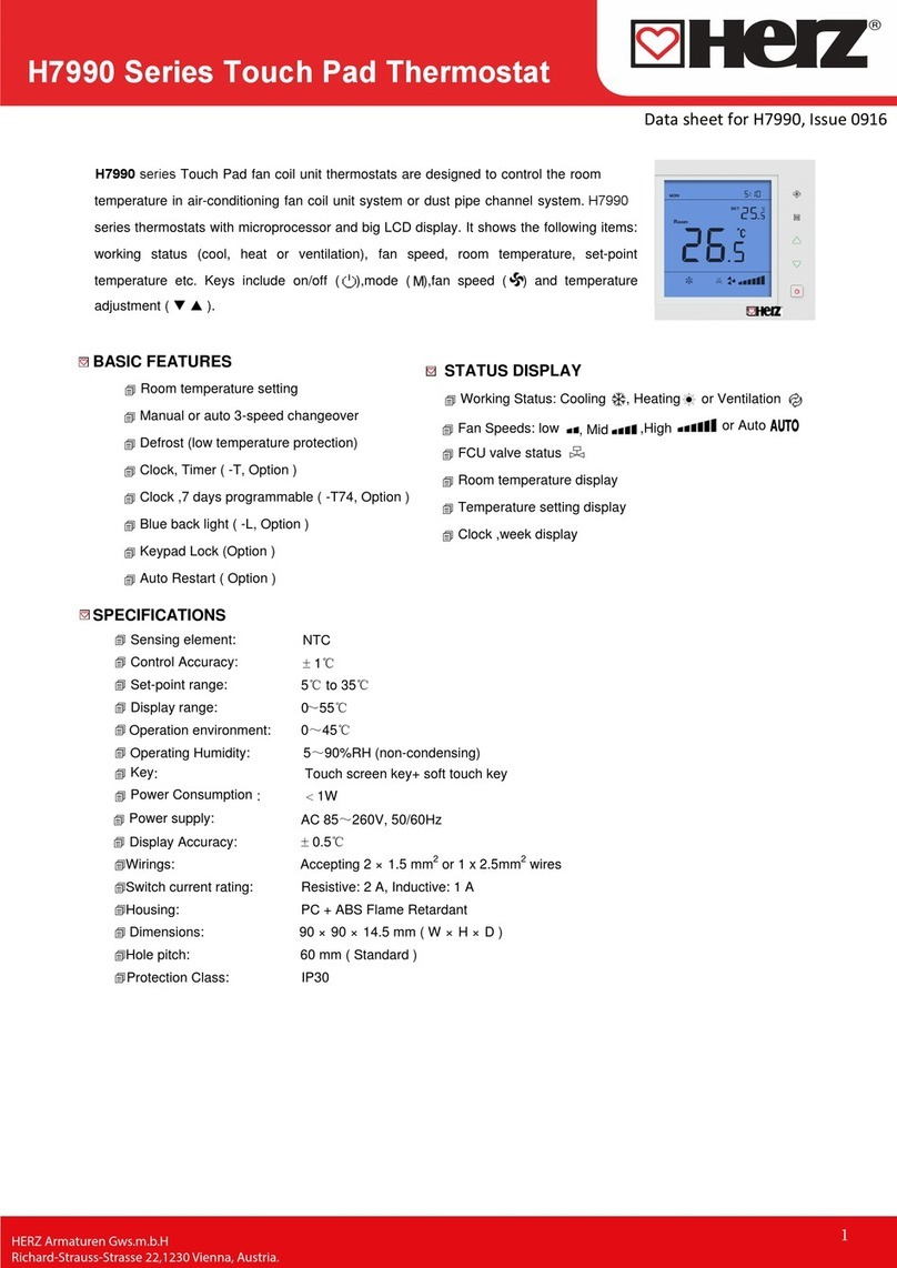
Herz 1 7795 01 User manual

Herz

Herz 1 7795 01 User manual

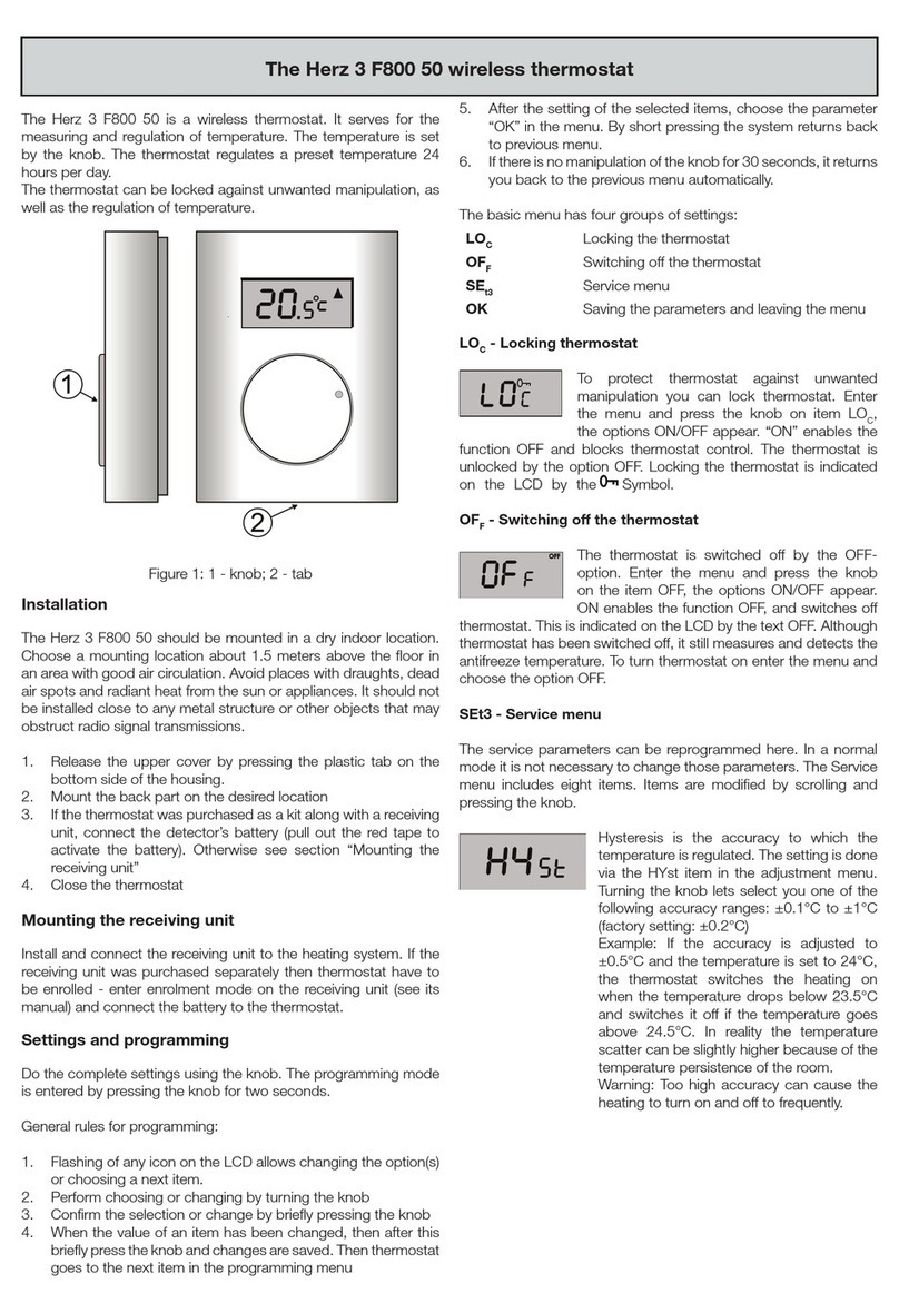
Herz 3 F800 50 User manual

Herz

Herz 3 F800 50 User manual

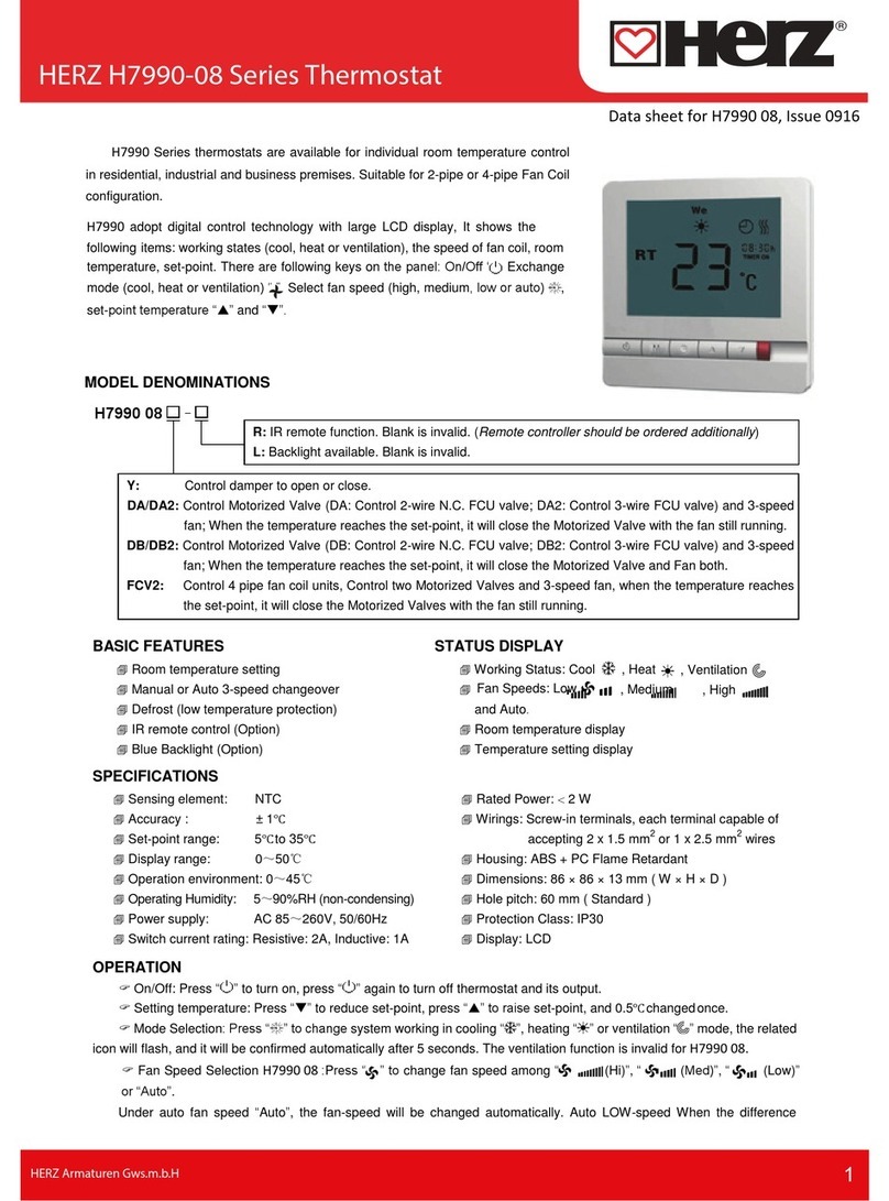
Herz H7990-08 Series User manual

Herz

Herz H7990-08 Series User manual

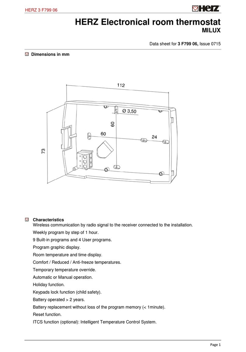
Herz MILUX 3 F799 06 User manual

Herz

Herz MILUX 3 F799 06 User manual

Herz 3 F800 55 User manual

Herz

Herz 3 F800 55 User manual

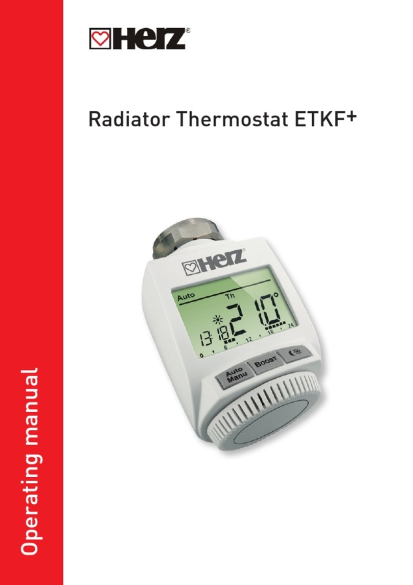
Herz ETKF+ User manual

Herz

Herz ETKF+ User manual

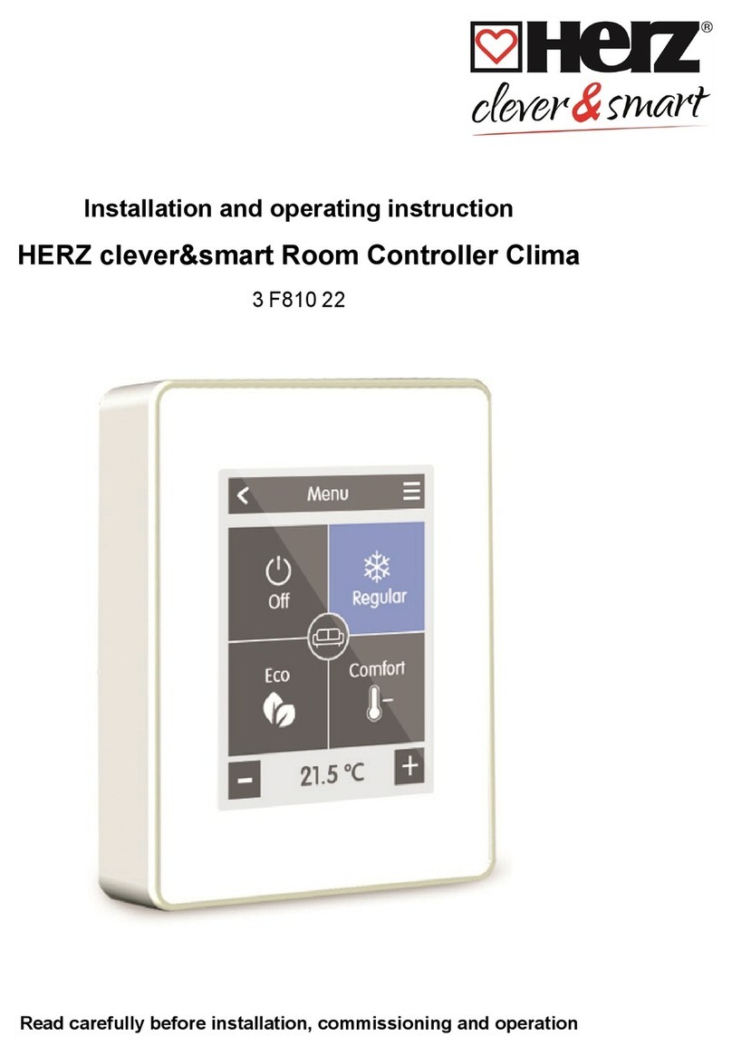
Herz clever&smart Clima 3 F810 22 User guide

Herz

Herz clever&smart Clima 3 F810 22 User guide

Herz F799 User manual

Herz

Herz F799 User manual

Herz H7711 Series User manual

Herz

Herz H7711 Series User manual

Herz H7990 Series User manual

Herz

Herz H7990 Series User manual

Herz ETKF+ User manual

Herz

Herz ETKF+ User manual

Popular Thermostat manuals by other brands

GE Security IS-ZW-TSTAT-100 Installation sheet

GE Security

GE Security IS-ZW-TSTAT-100 Installation sheet

Salus VS05 Installer's/user's manual

Salus

Salus VS05 Installer's/user's manual

hager EK051 user manual

hager

hager EK051 user manual

Robertshaw 9500 user manual

Robertshaw

Robertshaw 9500 user manual

Tesla TV500 user manual

Tesla

Tesla TV500 user manual

Drayton LP10RF Installation & user guide

Drayton

Drayton LP10RF Installation & user guide

Aprilaire 8800 Programmer's manual

Aprilaire

Aprilaire 8800 Programmer's manual

Resol DeltaSol BS/3 Mounting connection application examples operation troubleshooting

Resol

Resol DeltaSol BS/3 Mounting connection application examples operation troubleshooting

Heatmiser smartstat user manual

Heatmiser

Heatmiser smartstat user manual

Ferroli ZU0800009 Installation & user's instructions

Ferroli

Ferroli ZU0800009 Installation & user's instructions

ENDA ET1412 quick start guide

ENDA

ENDA ET1412 quick start guide

ClimateMaster ATM11C11 Submittal data

ClimateMaster

ClimateMaster ATM11C11 Submittal data

Friedrich RT7 Installation and operation guide

Friedrich

Friedrich RT7 Installation and operation guide

Johnson Controls T-4002 Control manual

Johnson Controls

Johnson Controls T-4002 Control manual

White Rodgers 1E56W-444 installation instructions

White Rodgers

White Rodgers 1E56W-444 installation instructions

Radio Thermostat CT50 Operation guide

Radio Thermostat

Radio Thermostat CT50 Operation guide

TOTALINE P474-1035 owner's manual

TOTALINE

TOTALINE P474-1035 owner's manual

Emerson Sensi ST75 installation manual

Emerson

Emerson Sensi ST75 installation manual

manuals.online logo
manuals.online logoBrands
  • About & Mission
  • Contact us
  • Privacy Policy
  • Terms and Conditions

Copyright 2025 Manuals.Online. All Rights Reserved.