Herz ETKF+ User manual

HERZ ETKF+
Page 1
HERZ ETKF+
Energy saving thermostatic head with receiver and accessories
Data sheet for 8251,Issue 0816
Dimension in mm
Version
1 8251 01 energy saving thermostatic head ETKF+ -
The energy saving thermostatic head ETKF+ is built with programmable
temperature, time control and wireless receiver.
Technical data
Setting range: 5 °C to 30 °C
Differntial: 0,5 K
Batteries: 2 X 1,5 V AA, LR6 battery included, typical life approx. 2 years
Receiver frequency: 868,3 MHz
Surrent consumption: Max. 100 mA
Ambient temperature: 5 °C to 50 °C
Linear stroke: 4,2 mm
Thread connection: M28 x 1,5
Field of application
The energy saving thermostatic head ETKF+ can be installed on all HERZ-TRVs with M28 x 1,5.
With adapters (available sepeately), it is possible to mount on the ETKF+ on valves from other
manufactures.
Function
Energy saving thermostatic head ETKF+ is use to control each radiator and can be also used to
control the room temperature. When airing the room, ETKF+ regulates the temperature
Mounting dimension (W x H x D): 60 x 65 x 100

HERZ ETKF+
Page 2
automatically to save heating costs. The communication of ETKF+ components to each other is
bidirectional. This ensures that information transmitted to reach the receiver.
Device Overview
Installation
Step 1: Inserting (replacing) the batteries
To insert the batteries into the energy saving thermostatic head ETKF+, please proceed as follows:
• Remove the battery compartment cover by pushing it forwards
• Insert two LR6/ mignon/ AA batteries in the battery compartment, making sure they are the
right way round
• Reattach the battery compartment cover and latch it into place
After inserting batteries, the radiator thermostat has to be mounted on the radiator. The radiator
thermostat starts an adaptating run afterwards.
A battery symbol ( ) indicates that the batteries need to be replaced. After removing the
batteries, you should wait approx. 1 minute before inserting the new ones. The service life of new
alkaline batteries is approximately two years.
This device does not support operation with rechargeable batteries.
Never recharge standard batteries. Doing so will present a risk of explosion. Do not throw
the batteries into a fire! Do not short-circuit batteries.
Used batteries should not be disposed of with regular domestic waste! Instead, take
them to your local battery disposal point.
Step 2: Setting the date and time of day
If batteries are inserted or replaced, the date and time is automatically requested after a brief
display of the firmware version number:
• Set the year, month, day, hour and minute with the handwheel and confirm with the Boost
button. The motor moves the control pin backwards during the setting of date and time.
• If "InS" and the rotating activity symbol " " are displayed, the motor still reverses. When only
"InS" is shown in the display, the energy saving thermostatic head ETKF+ can be installed on
the valve.
The ETKF+ can be configured already before installation. Press the Auto/ Menu button for this,
while „INS“ is shown in the display. After the programming has been completed, „InS“ is shown
again in the display and installation can take place.
Step 3: Installation of energy saving thermostatic head ETKF+
The ETKF+ is easy to install and can be done without draining heating water or intervening in the
heating system. No special tools are required, nor does the heating have to be switched off. The
brass union nut M28 x 1,5 attached to the ETKF+ can be used with HERZ thermostatic valves and

HERZ ETKF+
Page 3
thermostatic inserts with a M28 x 1,5 connection.
After inserting batteries, the ETKF+ has to be mounted on the radiator. The ETKF+ starts an
adaptating run afterwards, during the adapting it would be show “Ins” and symbol ( ) on the
display. After the symbol is shine on the display the ETKF+ can be mounted on the radiator.
After an adjustment run ( "AdA") is carried out to adapt to the valve.
• Set the ETKF+ on the valve
• Tighten nut tight firmly.
• Press the Boost button when the display reads "InS".
The ETKF+ performs adjustment run. Here "AdA" and the type icon ( ) appear on the display, at
this time no operation is possible. If the adjustment run initiated before mounting or an error
message (F1, F2, F3), press the Boost button and the motor back to the position "InS".
The “Teaching-In” can also aktivate during the “InS” on the display
Step 4: Configuration
The settings of the energy saving thermostatic head ETKF+ can be changed individually via the
configuration menu. Further information about changing the settings of the ETKF+ can be found in
the detailed operating manual available online for download on the HERZ Homepage.
Teaching-In
In order to be able to use the energy saving thermostatic head ETKF+ in your installation, you must
teach it in to the other devices first. Further information about “Teaching-In” the ETKF+ can be
found in the detailed operating manual available online for download on the HERZ homepage.
Restore factory settings
The factory settings of the energy saving thermostatic head ETKF+ can be restored manually.
Restoring the factory settings deletes all settings and information about taught-in devices.
• First remove the batteries from the battery compartment of the ETKF+
• Wait 60 seconds
• Press and hold down the three buttons (Auto/ Manu, Boost, ( )) while inserting the batteries
• Once the factory settings have been restored successfully, "rES" is displayed
Flashing Sequences
Error code on
the display
Problem
Solution
Empty battery
symbol ( )
Battery voltage too low
Replace batteries
F1
Valve drive sluggish
Check the installation; check
whether the pin on the heating
valve is stuck
F2
Actuating range too wide
Check the fastening of the
radiator thermostat
F3
Adjustment range too small
Check the heating valve;
check whether the valve pin is
jammed
F4
Device already taught-in to a
wall thermostat+
Make sure the device is no
longer taught-in to a wall
thermostat+ and restore the
factory settings Then you can
teach-In the device again.
F5
Temperature sensor
defective
Device defective - please
contact your specialist
manufactor.
F6
Battery voltage too low,
Valve moved to error
Position Replace the batteries
of the radiator thermostat
Slowly flashing
Connection to taught-in
Check the power supply and

HERZ ETKF+
Page 4
antenna symbol
( )
ETKF+ components lost
the batteries of taught-in
ETKF+ components.
Quickly flashing
Antenna symbol
( )
“Duty cycle” limit reached
The device can resume radio
communication after a waiting
time of approx. one hour
CAL
Routine descaling
is active
Automatic function
Information about radio operation
Radio transmission is performed on a non-exclusive transmission path, which means that there is a
possibility of interference occurring. Interference can also be caused by switching operations,
electrical motors or defective electrical devices.
The range of transmission within buildings can differ greatly from that available in the open
air. Besides the transmitting power and the reception characteristics of the receiver,
environmental factors such as humidity in the vicinity have an important role to play, as do
on-site structural, screening conditions.
Disposal and Safty instractions
Do not dispose of the device with regular domestic waste!
Electronic equipment must be disposed of at local collection points for waste electronic
equipment in compliance with local directives governing waste electrical and electronic
equipment.
The CE sign is a free trade sign addressed exclusively to the
authorities and does not
warrant any properties.
For technical support please contact our service agency.
The devices concerned are not intended for children and must not be used as toys.
Do not leave packaging material lying around, as children might be tempted to play with it,
which is extremely dangerous.
Do not open the device: it does not contain any components that need to be serviced by the
user. In the event of an error, please return the device to our service department.
Using the device for any purpose other than that described
in this brief instruction does not
fall within the scope of intended use and shall invalidate any warranty
or liability. This also
applies to any conversion or modification work. The device is intended for private use only.
Accessories
1 8251 02 window sensor+ contact for energy saving thermostatic head ETKF+
1 8251 03 wall thermostat+ for energy saving thermostatic head ETKF+
1 6350 03 Thermostats Adapter Ring for T&A Thermostatic Valves (threaded connection M28 x
1,5)
1 6357 11 Thermostats Adapter Ring „H“ (threaded connection M30 x 1,5)
1 6351 01 Thermostats Adapter Ring for Caleffi Thermostatic Valves (threaded connection M30 x
1,5)
1 6362 00 Thermostats Adapter Ring „D“ for Danfoss Valvs (Ø 23)
1 6362 01 Thermostats Adapter Ring „D“ for Danfoss screw valvs (threaded connection M20 x 1
old
version)
1 6362 11 Thermostats Adapter Ring „D“ for Danfoss screw valvs (threaded connection M23,5 x 1,5
current version)

HERZ ETKF+
Page 5
Window Sensor+ (1 8251 02)
Intended use
The window sensor+ is used to detect when a window is opened. If the window contact is taught-in
to a energy saving thermostatic head ETKF+
, these devices will automatically reduce the
temperature in the room during ventilation. Using the automatic temperature reduction function
whilst windows are open enables heating costs to be lowered.
The device may only be operated indoors and must be protected from the effects of damp and dust,
as well as solar or other methods of heat radiation. Using the device for any purpose other than
what is described in this operating manual does not fall within the scope of intended use and shall
invalidate any warranty or liability. This also applies to any conversion or modification work. This
device is intended for domestic use only.
Device Overview
The window sensor+ (A+ B) consists of a large electronic unit (A) and a small magnet (B). The
device is supplied with spacers and caps in white and brown.
C: Teach-In button
D: Device LED
Preparing for mounting
The window sensor+ consists of two elements: an electronic unit (A) and a magnet (B). The
electronic unit (A) must be mounted on the frame and the magnet (B) on the window. This enables
the electronic unit with a window opening. When the magnet is not in the immediate vicinity, then a
"window open" signal sent.
Installation site:
• First select the window that is frequently used for ventilation and which the window sensor+ is to
be attached to.
Mounting dimension in mm (W x H x D): electronic unit: 18,5 x 103,5 x 24,5
magnet: 12 x 48 x 12

HERZ ETKF+
Page 6
• The magnet (B) can be mounted on other side of the
electronic unit (A).
• The window sensor+ can be attached either vertically
or horizontally and can be positioned on the side or at
the top/ bottom of the window.
distance:
• Installation must be in parallel with a maximum spacing
of 8 mm.
• The magnet (B) must be centre-aligned with the
electronic unit (A).
• The magnet (B) and electronic unit (A) must be
attached at the same level (or as close to the same
level as possible) within the designated area.
Mounting:
Each of the elements can be fastened in two ways:
Adhesive strip mounting:
The surface on which you are mounting the element must be
clean and free of grease.
• Stick the adhesive strips supplied on the back of the
electronic unit (A) and on the back of the bracket for the
magnet (B).
• Then press the electronic unit (A) and the bracket onto the
frame and window.
Screw mounting:
Screw fastening damages the window frame. For those living in rented accommodation,
this could lead to a landlord making claim for compensation or holding back a tenant’s
deposit.
• Use a pen to mark the borehole positions (E) of the
electronic unit (A) and the magnet holder (B) on the
window frame and casement.
• If you are working with a hard surface, you should
pre-drill the holes marked (E) using a 1.5 mm drill.
• Use the countersunk head screws supplied to fasten
the wall brackets for the electronic unit (A) and
magnet (B).
If you are using the 14.5 mm high spacer,
you must first fasten it with two 2.2 x 16 mm
screws and then attach the magnet unit
(B) to it with another two screws. The
flatter spacers are simply fastened
together with the magnet using two 2.2 x
16 mm screws.
• Once you have fastened the wall bracket for the
magnet (B), insert the magnet. Then place the cap
on the magnet.
• Once you have fastened the wall bracket for the
electronic unit (A), attach the electronic unit.
Complete the mounting procedure by placing the
cap on the electronic unit (A). White and brown

HERZ ETKF+
Page 7
caps are supplied with the device.
Inserting (replacing) batteries
The window sensor+ is operated with two LR03/ micro/ AAA batteries.
• Remove the cap of the electronic unit (A) by pulling it forward and off the device (1). To release
the cap, squeeze it gently from above and below with your thumb and index finger (2).
• Carefully lift the release clip (3) from the side.
• Pull the electronic unit (A) forward (4) and off the
bracket.
• After removing the old batteries, please wait
approx. 60 seconds.
• Insert two new LR03/ micro/ AAA batteries in the
battery compartment (making sure that you insert
them the right way round).
• Place the electronic unit (A) back onto the bracket,
allowing it to latch into place.
• Put the cap back to the electronic unit (A). Make
sure that the LED opening on the cap is positioned
over the LED on the electronic unit (A).
Never recharge standard batteries. Do not throw the batteries into a fire. Do not expose
batteries to excessive heat. Do not short-circuit batteries. Doing so will present a risk of
explosion.
Used batteries should not be disposed of with regular domestic waste! Instead, take them
to your local battery disposal point.
Teaching-In
In order to be able to use the window sensor+ in your installation, you must teach it in to your
system first.
You can teach in the window sensor+ directly to the wall thermostat+ (Room solution) or the energy
saving thermostatic head ETKF+ (Radiator solution).
• Put the device to be taught (e.g. wall thermostat+) into
“Teaching-In” mode (according to the corresponding operating
manual).
• To activate “Teaching-In” mode of the window sensor+, press
and hold down the “Teaching-In” button (C) on the electronic
unit (A) for at least 3 s. The device LED (D) starts to flash.
• Successful “Teaching-In” of the window sensor+ is confirmed
by the LED (D) lighting up once.
• Place the cap on the electronic unit (A).
To initialise the window sensor+, once open and close the
window to which the window sensor+ is mounted.
The window sensor+ can be taught-in to one wall thermostat+/ energy saving thermostatic
head ETKF+ only.
Exception: synchronous solution (max. 2energy saving thermostatic head ETKF+ and
max. Three window sensor ) vide page 14 room solution
Restore factory settings
The factory settings of the window sensor+ can be restored manually. Restoring the
factory settings deletes all settings and information about taught-in devices.
• First remove the batteries from the electronic unit.
• Wait 60 seconds.
• Hold down the “Teaching-In” button (C) and at the same time re-insert the batteries.
• Press and hold down the “Teaching-In” button (C) until the LED (D) starts to flash.
• Release the “Teaching-In” button (C); the factory settings are restored.

HERZ ETKF+
Page 8
Flashing sequences
The LED’s (D) flashing sequences have different meanings:
Flashing sequence
Meaning
1x flash
Window open/ closed, radio
command sent successfully
2x flashes
“Duty cycle” limit reached. The
device will communicate again
after max. one hour.
3x flashes
Error message: wireless command
not sent successfully
Technical characteristics:
Supply voltage: 2x 1,5V AAA, Micro LR03 battery included, typical life
approx 5 years
Current consumption: Max. 50 mA
Degree of protection: IP 20
Ambient temperature: 0 to 50 °C
Transmission frequency: 868,3 MHz
Receiver category:SRD category 2
Range of transmission in open air: 100 m
Wall Thermostat+ (1 8251 03)
Mounting dimension in mm (W x H x D): 86 x 86 x 21,5

HERZ ETKF+
Page 9
Device Overview:
A: Mounting plate
B: Clip on frame
C: Electronic unit
(D) Automatic mode (Auto), manual modus (Manu), holiday function ( ), boost-function ( ),
open-window-function ( ), operating lock ( )
(E) Weekday, empty battery symbol ( ), radio synchronicity ( ), comfort-/reduction-
temperature ( ), time/date
(F) Bar chart of the programmed heating phases of the current day
(G) Confort temperature button ( ): switching to comfort temperature
(H) Reduction temperature button ( ): switching to comfort temperature
(I) Mode-/ Menu-button: change the operating modus and open the configuration menu; exit/ back
in the menu
(J) Boost-/ OK-button: confirm settings and activate the boost-function
(K) (-) button: reduce the set point temperature, browse in the menu
(L) (+) button: increase the set point temperature, browse in the menu
(M) set point-/ actual-temperature
Intended use:
The wall thermostat+ is responsible for regulating the room temperature within the system. With the
wall thermostat+ up to 8 energy saving thermostatic heads ETKF+ can be comfortably regulated in
a room. The wall thermostat+ has an internal sensor that measures the temperature in the room
and cyclically transmits it to the ETKF+. Communication between the components is bidirectional.
This ensures that the information sent reaches the recipient.
The device may only be operated indoors and must be protected from the effects of damp and
dust, as well as solar or heat radiation.
Using the device for any purpose other than that described in this brief instruction does not fall
within the scope of intended use and shall invalidate any warranty or liability. This also applies to
any conversion or modification work. The device is intended for private use only.
Inserting (replacing) batteries:
As-delivered condition:
When you are starting up the device for the first time, first remove the mounting plate (A) on the
rear of the wall thermostat+.
• Hold the wall thermostat+ firmly in one hand and pull of themounting plate at one corner.
A
B
C
D
E
F
G
H
M
L
K
I
J

HERZ ETKF+
Page 10
Mounted condition:
Once mounted, the wall Thermostat+ can easily be pulled of the mounting plate and out of the
frame.
• Pull sideways at the frame to remove the electronic unit of the wall together with the frame.
Replacing batteries:
• Turn the wall thermostat+ over to remove or insert the batteries.
• After removing the old batteries, please wait approx. 60 seconds.
• Insert two LR03/ micro/ batteries in the battery compartments (making sure that you insert them
the right way round).
• Put the electronic unit back into the frame (B).
The empty battery symbol ( ) indicates that the batteries need to be changed. If, in
addition, a "V" or "S" are displayed, the batteries of a taught-in ETKF+ (V) or window
sensor+ (S) have to be replaced.
Never recharge standard batteries. Doing so will present a risk of explosion. Do not throw
the batteries into a fire! Do not short-circuit batteries.
Used batteries should not be disposed of with regular domestic waste! Instead,
take them to your local battery disposal point.
Mounting:
You can either use screws or adhesive strips to mount the wall thermostat+ to a wall in the frame
supplied or integrate it into an existing switch.
Adhesive strip mounting:
• Choose a site for installation. The surface on which you are mounting the room thermostat must
be clean, dry and free of grease.
• For mounting of the assembled wall thermostat+, attach the adhesive strips to the back side of
the mounting plate (A). You should be able to read the letters on the back side (according to
figure).
• Remove the protective film from the adhesive strips.
• Press the assembled wall thermostat+ with the back side to the wall in the position where it
should subsequently be attached.

HERZ ETKF+
Page 11
Screw mounting:
• Choose a site for installation.
Make sure that no electricity or similar lines run in the wall at this location.
• Position the mounting plate on the desired site on the wall. Make sure that the arrow on the
mounting plate is pointing upwards.
• Use a pen to mark the positions of 2 bore holes (1) (diagonally opposite) in the mounting plate on
the wall. The bore holes (2) can be used for installation with a flush mounting box.
• Now drill the bore holes. If you are working with a stone wall, drill the marked two 5 mm holes and
insert the plugs supplied. If you are working with a wooden wall, you can pre-drill 1.5 mm holes to
make screws easier to insert.
• Now drill the bore holes. If you are working with a stone
wall, drill the marked two 5 mm holes and insert the
plugs supplied. (If you are working with a wooden wall,
you can pre-drill 1.5 mm holes to make screws easier to
insert).
• Use the screws and plugs supplied to fasten the
mounting plate to the wall.
• Attach the electronic unit with the frame on the mounting
plate. Make sure that the arrows on the back side of the
electronic unit point upwards and that the clips on the
mounting plate latch into the openings on the electronic
unit.

HERZ ETKF+
Page 12
Setting data and time:
After inserting or replacing batteries the firmware version number will be shown briefly. Accordingly,
date and time will be requested automatically. Settings can be changed with the (+) and (-) buttons
and confirmed with the Boost/ OK button.
• Set the year, month and date and confirm each setting with the Boost/ OK button.
Year: Month and day:
• Set the time and confirm your settings with the Boost/ OK button.
Hours: Minutes:
Once the time and date were entered, the wall thermostat+ changes back to normal operating
mode.
Teaching-In:
In order to be able to use the wall thermostat+ in your installation, you must teach it in to the other
devices first. Further information about “Teaching-In” the wall thermostat+ can be found in the
detailed operating manual available online for download on www.herz.eu.
Configuration of the System:
If you use the wall thermostat+ in the Room solution, you can individually change all settings of
your system (e.g. configuration of week programs) directly via the device. Further information about
changing the settings of the wall thermostat+ can be found in the detailed operating manual
available online for download on www.herz.eu
Restore factory settings:
The factory settings of the wall thermostat+ can be restored manually, e. g. if you want to re-install
an incorrectly operating system. Restoring the factory settings deletes all settings and information
about “Teaching-In” devices.
In the Room solution the factory settings of the wall thermostat+ can be restored as
follows:
• Press the Mode/Menu button for at least 3 seconds.
• Select the “rES” menu item with the (+) and (-) buttons.
• Confirm your selection using the Boost/ OK button.
• "ACC" will be displayed. Confirm the factory reset with the Boost/ OK button.
You can still restore the factory settings as follows:
• Remove a battery and wait for 60 seconds.
• Press and hold down the reduction ((((()), Ok and the (-) button simultaneously and insert the
battery at the same time.
• When "rES" appears on the display, the reset was performed and the buttons can be released.

HERZ ETKF+
Page 13
Flashing Sequences and Maintenance:
Errorcode
Problem
Solution
Batterysymbol( )
Battery voltage to low
Replace battery
F5
Temperature sensor defect
Replace device
Slowly flashing antenna
symbol ( ) Connection on to taught-in
components lost
Check the power supply and
the batteries of taught-in
components
Quickly flashing antenna
symbol ( ) “DutyCycle” limit reached
The device can resume radio
communication after a waiting
time of approx. one hour
The product is out of maintenance. Repairs are only by specialist. Clean the product with a soft,
clean, dry cloth. To remove heavier dirt, use a cloth which is slightly moistened with lukewarm
water. Do not use solvent-based cleaning agent, the plastic housing and the labels can be
attacked.
Information about radio operation
Radio transmission is performed on a non-exclusive transmission path, which means that there is a
possibility of interference occurring. Interference can also be caused by switching operations,
electrical motors or defective electrical devices.
The range of transmission within buildings can differ greatly from that available in the
open air. Besides the transmitting power and the reception characteristics of the receiver,
environmental factors such as humidity in the vicinity have an important role to play, as
do on-site structural/ screening conditions.
Technical Characteristics
Supply voltage: 2x 1.5 V AAA, LR03 micro battery included,
typical life approx 2 years
Current consumption: Max. 30 mA
Degree of protection: IP 20
Ambient temperature: 5 to 50 °C
Radio frequency: 868.3 MHz
Receiver category: SRD category 2
Typ. open area RF range: 100 m
Wireless solution for energy saving thermostatic head ETKF+
Room solution:
max. 1 wall thermostat+
max. 8 energy saving thermostatic heads ETKF+
max. 8 window sensor+

HERZ ETKF+
Page 14
Room synchronous solution:
max. 2 energy saving thermostatic heads ETKF+
max. 3 window sensor+
Safety and disposal Instruction:
The device is not a toy; do not allow children to play with it. Do not leave packaging
material lying around, as it can be dangerous in the hands of a child.
Do not open the device: it does not contain any components that need to be serviced by
the user. In the event of an error, please return the device to the service department.
The device may only be operated indoors and must be protected from the effects of
damp and dust, as well as solar or heat radiation.
Using the device for any purpose other than that described in this brief instruction does
not fall within the scope of intended use and shall invalidate any warranty or liability. This
also applies to any conversion or modification work. The device is intended for private
use only.
Do not dispose of the device with regular domestic waste.
Electronic equipment must be disposed of at local collection points for waste electronic
equipment in compliance with the Waste Electrical and Electronic Equipment Directive.
The CE sign is a free trading sign addressed exclusively to the authorities and does not
include any warranty of any properties.
For technical support please contact your service agency.
All specifications and statements within this document are according to information available at the time of printing and meant for informational
purpose only. Herz Armaturen reserves the right to modify and change products as well as its technical specifications and/or it functioning
according to technological progress and requirements. It is understood that all images of Herz products are symbolic representations and
therefore may visually differ from the actual product. Colours may differ due to printing technology used. In case of any further questions don’t
hesitate to contact your closest HERZ Branch-office.
Other manuals for ETKF+
1
This manual suits for next models
1
Other Herz Thermostat manuals
Herz
Herz 3 F800 50 User manual
Herz
Herz 3 F800 55 User manual
Herz
Herz H7714 Series Operating manual
Herz
Herz clever&smart Clima 3 F810 22 User guide
Herz
Herz MILUX 3 F799 06 User manual
Herz
Herz H7711 Series User manual
Herz
Herz F799 User manual

Herz
Herz 1 7795 01 User manual
Herz
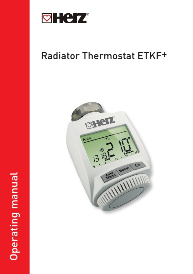
Herz ETKF+ User manual
Herz
Herz H7990-08 Series User manual
Popular Thermostat manuals by other brands
Honeywell
Honeywell RTHL2410 series operating manual
HOTOWELL
HOTOWELL HTW-MT08 Series Installation and operation manual
dixell
dixell XR20CX Installing and operating instructions
Mohlenhoff
Mohlenhoff RD 40203 manual

Honeywell
Honeywell THX9000 Prestige HD System installation guide

Crestron
Crestron CHV-TSTATEX quick start guide
