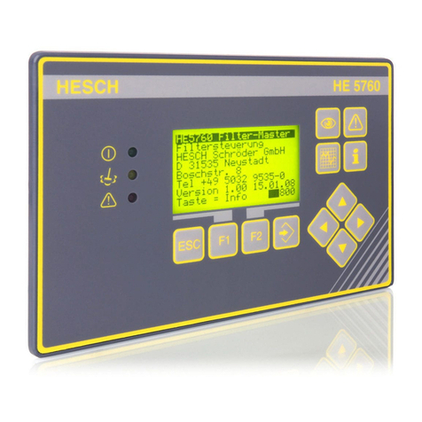
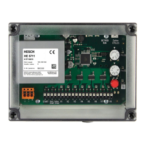
HESCH HE 5712 Compact User manual

Solenoid valve control
HE 5712 Compact / Modular
Operating Instructions
(Original German version)
372048 | Version 1.4

2
HE 5712 Operating Instructions
# 372048 | Version 1.4
Impressum
HESCH Industrie-Elektronik GmbH
Boschstrasse 8
31535 Neustadt
Telefon: +49 5032 9535–0
Fax: +49 5032 9535–99
Internet: www.hesch.de
Hanover District Court
Commercial Register 111184
VAT.-Id. No. DE813919106
General Management
Walter Schröder, Werner Brandis
Editor:
HESCH Industrie Elektronik GmbH, Documentation Department
Copyrights
© Copyright 2020 HESCH Industrie-Elektronik GmbH. All rights reserved.
The content including pictures and the design of these operating
instructions are subject to copyright protection and other laws for the
protection of intellectual property. The distribution or modification of the
contents of this manual is not permitted. Furthermore, this content may not
be copied, distributed, changed or made accessible to third parties for
commercial purposes.

HE 5712 Operating Instructions
# 372048 | Version 1.4
3
TABLE OF CONTENTS
1. LEGAL PROVISIONS................................................................................................................................... 5
2. SAFETY INFORMATION ............................................................................................................................. 6
2.1 SYMBOLS AND BASIC SAFETY INSTRUCTIONS...................................................................................................... 6
2.2 SAFETY IN THE INDIVIDUAL OPERATING PHASES................................................................................................... 7
3. DEVICE DESCRIPTION................................................................................................................................ 9
3.1 OVERVIEW.................................................................................................................................................. 9
3.1.1 HE 5712 Compact ............................................................................................................................ 9
3.1.2 HE 5712 Modular........................................................................................................................... 10
3.2 DISPLAY AND OPERATING ELEMENTS.............................................................................................................. 12
3.3 DIFFERENTIAL PRESSURE COLUMN.................................................................................................................. 13
3.4 TECHNICAL DATA ....................................................................................................................................... 14
4. MOUNTING ............................................................................................................................................ 16
4.1 DIMENSIONS ............................................................................................................................................. 16
4.1.1 HE 5712 Compact .......................................................................................................................... 16
4.1.2 HE 5712 Modular Operating unit (panel mounting housing) ....................................................... 17
5. ELECTRICAL COMMISSIONING ................................................................................................................ 18
5.1 SAFETY INFORMATION................................................................................................................................. 18
5.2 READ OUT AND SET PASSWORD ..................................................................................................................... 19
5.3 SUPPLY VOLTAGE........................................................................................................................................ 19
5.3.1 Compact Housing .......................................................................................................................... 19
5.3.2 Housing for Panel Mounting ......................................................................................................... 20
5.4 VALVE CONNECTIONS .................................................................................................................................. 21
6. PARAMETERISATION .............................................................................................................................. 22
6.1 PARAMETERISATION WITH DEVICE KEYBOARD.................................................................................................. 22
6.2 PARAMETER TABLE..................................................................................................................................... 23
6.3 OFFSET FOR ZEROING.................................................................................................................................. 26
6.4 PARAMETERISATION WITH SERVICE PC........................................................................................................... 26
6.5 ENABLE /DISABLE PRECOATING.................................................................................................................... 26
6.6 RESET DEFAULT SETTINGS............................................................................................................................ 27
7. OPERATION OF THE CONTROL ................................................................................................................ 28
7.1 NORMAL OPERATION.................................................................................................................................. 28
7.2 TEST FUNCTION ......................................................................................................................................... 29
7.3 DISPLAY MODE.......................................................................................................................................... 29
7.4 DIFFERENTIAL-PRESSURE MEASUREMENT ........................................................................................................ 30
8. ERROR MESSAGES .................................................................................................................................. 32
9. MAINTENANCE AND SERVICE ................................................................................................................. 33

4
HE 5712 Operating Instructions
# 372048 | Version 1.4
Document History
Version
Date
Description
1.0
2018-06-14
First draft (Translation)
1.1
2018-12-18
Chapter 6.7: Pictures for PARA and ENTER key corrected
1.2
2019-08-08
Chapter Electrical Commissioning: Note added for entering
password prior to commissioning.
1.3
2020-01-07
Chapter 5.3 and 7.1: „12,14,16“ added for mass in the note.
Position of the note in 7.1. adapted. Position 11, 13, 15 added in
7.1
1.4
2020-03-11
Chapter 5 Electrical Commissioning: Note for entering password
deleted,
Chapter 5.2 Readout and set password: added
Chapter 6.1 Parameterization with device keyboard: revised
Chapter 6.6 Reset Default settings: revised,
Current chapter 6.6 Parameter Protection / Password: deleted

HE 5712 Operating Instructions
# 372048 | Version 1.4
5
1. Legal provisions
Manufacturer
HESCH Industrie-Elektronik GmbH, Boschstraße 8, D-31535 Neustadt, Germany
Intended Use
The solenoid valve control HE 5712 is used for cleaning industrial filter systems.
The controller can be operated within the operating and environmental conditions
approved in this manual without impairing its safety.
The manufacturer is not liable for improper use and any resulting personal injury or
material damage; the risk is borne solely by the user. Failure to comply with the above
criteria for intended use may result in the expiry of the warranty and liability for the
device.
Personnel qualification
All work on the solenoid valve control may only be carried out by qualified electricians with
sufficient knowledge in the field of electrical engineering.
Device Safety
The device has been constructed and tested in accordance with VDE 0411 / EN 61010-1 and
has left the factory in perfect safety condition. To maintain this condition and ensure safe
operation, the user must observe the notes and warnings described in this manual.

6
HE 5712 Operating Instructions
# 372048 | Version 1.4
2. Safety Information
2.1 Symbols and Basic Safety Instructions
This chapter contains important safety regulations and notes. To protect against personal
injury and material damage, it is necessary to read this chapter carefully before working with
the device.
Symbols used
The following symbols are used in this manual. All safety instructions have a uniform structure.
Personal Injury Warning!
The severity of the danger is indicated by the respective signal word.
Explosible region warning sign!
High Voltage Warning!
Warning of material damage caused by electrostatic charge!
Property Damage Warning!
Note!
Identifies possible malfunctions and indicates optimum operating
conditions.
Signal Words
DANGER!
Indicates an imminently hazardous situation, which, if not avoided, will result in death or
serious injury.
WARNING!
Indicates a potentially hazardous situation, which, if not avoided, could result in death or
serious injury.
WARNING!
Indicates a hazardous situation, which, if not avoided, could result in minor or moderate injury.

HE 5712 Operating Instructions
# 372048 | Version 1.4
7
2.2 Safety in the individual operating phases
When installing the control unit and during operation, the following safety instructions must be
observed.
Danger of Electrocution!
Before working on the device, switch off all power supplies used. The
electrical cables must be laid according to the respective national
regulations (in Germany VDE 0100). The measuring lines must be laid
separately from the mains leads. The connection between the connection
for the functional earth (in the respective device carrier) and a protective
conductor must be established.
Danger of Electrocution!
Any interruption of the protective conductor in the device carrier can lead
to the device becoming dangerous. Intentional interruptions are not
permitted. If it is suspected that safe operation is no longer possible, the
device is to be decommissioned and secured against unintentional
operation.
Danger of Electrocution!
Do not open the device while it is live! When opening the devices or
removing covers and parts, live parts may be exposed. Connecting points
can also be live!
WARNING!
The device must never be put into operation despite any visible damage.
WARNING!
During installation, commissioning, maintenance and troubleshooting,
observe the accident prevention regulations applicable to your system,
e.g. DGUV Regulation 3 "Electrical installations and equipment".
WARNING!
Clean dirty contacts with oil-free compressed air or with spirit and a lint-
free cloth.
Warning of material damage caused by electrostatic charge!
Observe the safety measures according to BS EN 61340-51/-3 to avoid
electrostatic discharge!
Explosion Prevention!
The HE 5712 Compact (Fig. 1)is suitable for use in explosion zone 22.
Before opening the device, it is essential to ensure that no explosive
environmental conditions, such as dust generation, exist

8
HE 5712 Operating Instructions
# 372048 | Version 1.4
Machine Identification
The HE 5712 Compact (Fig. 1)is marked with:
II3D
Device category
Use in Zone 22 for dust during normal operation
Ex
Designates an electrical equipment
Tc
Type of ignition protection:
Protection by housing
IIIC
Dust group:
Conductive dusts
T135°C
Temperature class
Maximum permissible surface temperature
Dc
Device protection level:
Use in Zone 22 for dust
IP65
Protection class
Dust-tight and protected against water jets
Troubleshooting!
At the beginning of troubleshooting, all possible sources of faults on
additional devices or supply lines (measuring lines, wiring, downstream
devices) should be taken into consideration. If the fault was not found
after checking these points, we recommend sending the device to the
supplier.
Decommissioning!
Switch off the power supply on all poles if the device is to be
decommissioned. Secure the device against unintentional operation!
If the device is connected to other devices and / or equipment, the effects
must be considered and appropriate precautions taken before switching
off.
The following special regulations must be observed:
Connect cables professionally in glands.
Close not needed housing bores with locking bolts.
Cleaning of the housing is only permitted with moist cleaning agents to avoid static
charging.
Cleaning is necessary to prevent increased dust generation on the device.
Operation under voltage, in zone 22, only in closed state.
Before closing, ensure that the device housing is free of dust

HE 5712 Operating Instructions
# 372048 | Version 1.4
9
3. Device Description
The solenoid valve control HE 5712 is available in different versions.
3.1 Overview
3.1.1 HE 5712 Compact
HE 5712 (Compact)
HE 5712 (Compact) Connection area

10
HE 5712 Operating Instructions
# 372048 | Version 1.4
3.1.2 HE 5712 Modular
HE 5712 (Modular) Operating Unit
Rear panel HE 5712 (modular) Operating Unit

HE 5712 Operating Instructions
# 372048 | Version 1.4
11
HE 5712 (Modular) control unit in standard rail enclosure (100 - 240 V AC)

12
HE 5712 Operating Instructions
# 372048 | Version 1.4
3.2 Display and Operating Elements
Display and Operating Elements
Symbols
Meaning
Operating message
Cleansing active
Alarm active
Pulse time
Break time
The number of valves is shown in the display and can be changed
Post-cleaning cycles are shown in the display and can be changed
Total / partial cycle is shown in the display and can be changed
Interruption due to defective valve line or solenoid valves
Short circuit of a valve line (overcurrent)
Differential pressure is shown in the display
The active valve number is shown in the display

HE 5712 Operating Instructions
# 372048 | Version 1.4
13
Symbols
Meaning
PARA key: parameterisation mode On/Off
UP key: increase the displayed value
DOWN key: decrease the displayed value
ENTER key: Confirm the displayed value
TEST key: Test mode On/Off
Display
Normal operation: current differential pressure, current valve
Parameterisation mode: parameter values and alarm notes
Switch with UP / DOWN keys
3.3 Differential pressure column
Differential pressure column
Delta-P measuring range
High alarm
Upper threshold - start cleaning
Lower threshold - stop cleaning
Low-Alarm
Post-cleaning Threshold
Zeroing

14
HE 5712 Operating Instructions
# 372048 | Version 1.4
3.4 Technical Data
Technical Data
Measuring range (please refer to
the nameplate)
0…35 mbar
0…90 mbar
0…450 mbar
Max. differential pressure:
Measuring range 0…35 mbar: 160 mbar
Measuring range 0…90 mbar: 400 mbar
Measuring range 0…450 mbar: 2000 mbar
Medium
Air and dry, non-aggressive gases
Basic accuracy:
± 1 % of the final value
Temperature drift
± 0.05 % / K of the final value
Hysteresis
± 0.5 % of the final value
Intended use:
Solenoid valve control for cleaning industrial filter
systems
Valve outputs:
Max. 8 outputs, 24 V DC
Supply voltage:
(Please refer to the nameplate on
the device.)
• 100–240 VAC / 50 –60 Hz
• 24 VDC ±10% safety extra-low voltage (SELV)
Power consumption:
30 VA with 100–240 VAC control
Max. 30 W with 24 VDC controls
Pulse time:
0.01 –9.99 seconds adjustable
Break time:
1.0 –999 seconds adjustable
Display:
7-segment display, 3-digit, 14 mm height, white
For differential pressure/valve display, parameter and
alarm values
LEDs:
14 LEDs for status displays, 16 LEDs for differential
pressure column
Keys:
PARA (ESC), UP, DOWN, ENTER, TEST
Analogue output:
4 - 20 mA, max. permissible load: 400 Ω
Digital inputs:
Start Post-cleaning release
Relay output:
1 change-over contact 250 VAC, 5 A as combined
operating and fault signal
Interfaces:
USB device, type B for writing and reading the
parameters (USB / TTL adapter required)
Air / creepage distances:
Pollution degree 2, overvoltage category II
EMC:
Interference emission: BS EN 61000-6-4
Resistance to interference: BS EN 61000-6-2
Housing dimensions:
Compact housing
231 × 125 × 90 mm
Modular (panel mounting)
200 × 122 × 30 mm
Modular
(control unit )
192 × 128 × 63 mm
Connection set for the
Compact housing
(Option)
2 × M32 with multiple sealing insert for 6 cables
with 6mm diameter
3 × M16 for supply and communication
Electrical connections
Supply: Cross-section rigid/flex:max. 2.5 mm2, flex.:
max. 1.5 mm2 with ferrule: Rest: cross-section
rigid/flex.: max. 1.5 mm2, flex.: max. 0.75 mm2 with
ferrule
Pneumatic connections
Pressure measuring line:
Push-in bulkhead fitting for Ø6 mm hose
Mounting
Compact housing
Wall mounting. Mounting position: vertical
Modular
Panel-mounting housing, vertical mounting position
Control unit: standard rail

HE 5712 Operating Instructions
# 372048 | Version 1.4
15
Ambient conditions
Climate
Storage
-20° –+70°C
Transport
-40° –+85°C
Operation
Compact housing
-20°C –+50°C
in EX Zone 22: -20° –+40°C
Modular
-20°C –+50°C
No EX approval
Relative humidity
Relative humidity 95%, no condensation allowed, KUF
according to DIN 40400
Subject to technical changes.

16
HE 5712 Operating Instructions
# 372048 | Version 1.4
4. Mounting
The ambient temperature at the installation point must not exceed the permissible
temperature for nominal use specified in the technical data. The device version in compact
housing may be mounted in areas of explosion class EX ATEX Zone 22 (see also the
nameplate on the device housing) The special regulations must be observed, see chapter 2.2
Safety in the individual operating phases on 7.
4.1 Dimensions
4.1.1 HE 5712 Compact
Dimensions of compact housing

HE 5712 Operating Instructions
# 372048 | Version 1.4
17
4.1.2 HE 5712 Modular Operating unit (panel mounting housing)
Operating unit (panel mounting housing)
Scope of Delivery
HE 5712
Operating Instructions
Drilling jig (only for the operating unit - HE 5712 Modular)
Note!
Upon receipt, check the delivery for completeness and visible defects. In
the event of a complaint, contact your responsible HESCH representative
immediately.
Section
170 × 105 mm

18
HE 5712 Operating Instructions
# 372048 | Version 1.4
5. Electrical Commissioning
Before switching on the device, observe the following points:
Connect the cable firmly to the glands.
The power supply must correspond to the voltage indicated on the nameplate.
The device may only be operated in closed condition.
The temperature restrictions specified for the use of the device must be observed
before and during operation.
Ensure that the FE conductor is connected.
The patch cable between the control unit and the operating unit may only be
plugged/unplugged when switched off.
5.1 Safety Information
Danger of Electrocution!
Electrical installation must only be carried out when the power is
disconnected.
Warning of material damage caused by electrostatic charge!
Observe the safety measures according to BS EN 61340-51/-3 to avoid
electrostatic discharge!
Note!
Work on the electronics may only be carried out by qualified personnel.

HE 5712 Operating Instructions
# 372048 | Version 1.4
19
5.2 Read out and set password
1.
Switch on the device while keeping both keys UP and
DOWN pressed for 5 seconds. When the 5 seconds are up,
"cod" is displayed and afterwards the currently set
password. In state of delivery, the pre-assigned password
001 is displayed (see also 6.2 Parameter Table)
2.
Press the ENTER key to set a new a password.
3.
The first number starts blinking. Set the requested value
with the UP and DOWN keys.
4.
When the requested key is displayed, press the ENTER
key.
5.
Repeat step 3 and 4 to set the second and third number.
6.
After the last number has been acknowledged with the
ENTER key, HE 5712 is displayed and the control starts.
5.3 Supply voltage
Take the value of the correct supply voltage from the nameplate. There are device versions
with 100 - 240 V AC and device versions only with 24 V DC mains voltage.
5.3.1 Compact Housing
Open the housing on the right hinge lock using a slotted screwdriver: (Figur 10):
Opening the housing of the HE 5712 Compact

20
HE 5712 Operating Instructions
# 372048 | Version 1.4
HE 5712 Compact with 24 V DC supply voltage
5.3.2 Housing for Panel Mounting
The supply voltage is applied centrally to the control unit .
The operating unit gets its 24 V DC supply via a patch cable (CAT5 or better) from the control
unit . The patch cable must not be longer than 328 feet (patch cable not included in the scope
of delivery).
Electrical commissioning of the HE 5712 Modular (100 - 240 V AC)
Electrical commissioning of the HE 5712 Modular (24 V AC)
Patch cable
(CAT 5 or better)
Max. 328 feet
Patch cable
(CAT 5 or better)
Max. 328 feet
▲Control unit
▲Operating unit
▲Control unit
▲Operating unit
This manual suits for next models
1
Table of contents
Other HESCH Control Unit manuals
