HESCH HIMOD HE 5820 DI User manual
HIMOD® Function Module
HE 5820 DI
Operation manual
(English)
# 38101017 | 12.12.2014

Disclaimer
HESCH Industrie-Elektronik GmbH
Boschstraße 8
D-31535 Neustadt
Germany
Tel. +49 (0) 5032 9535–0
Fax +49 (0) 5032 9535–99
Website: www.hesch.de
District Court Hanover
HRB 111184
Tax no.: 34/200/22524
VAT no.: DE813919106
Executive Board:
Walter Schroeder, Werner Brandis
Publisher:
HESCH Industrie Elektronik GmbH, Documentation Department
Copyrights
© Copyright 2014 HESCH Industrie-Elektronik GmbH. All rights reserved.
The content of this operating manual incl. images and design are subject
to the protect of copyright and other laws regarding the protection of
intellectual property. The distribution or modification of this manual is not
permitted and its content may not be copied, distributed, modified or made
availabe to third parties for commercial use.

Table of Contents
1General ......................................................................................................... 4
1.1Features......................................................................................................... 4
1.2HIMOD System.............................................................................................. 5
2Safety Instructions....................................................................................... 6
2.1Maintenance, Repair, Converting................................................................... 7
2.2Cleaning......................................................................................................... 7
3Assembly...................................................................................................... 8
3.1Plug Connectors ............................................................................................ 9
3.2Front View and Indications........................................................................... 10
4Electrical Connection ................................................................................ 11
4.1Connection Diagram.................................................................................... 11
4.2Connection Specification ............................................................................. 12
4.2.1HE 5820 PNP Art. No.: HE58200000........................................................... 12
4.2.2HE 5820 NPN Art. No.: HE58201000 .......................................................... 12
4.2.3HE 5820 POT Art. No.: HE58203000........................................................... 12
5Functional Description.............................................................................. 13
5.1Module Functions Parameterisation Table................................................... 13
5.1.1Polarity and Debounce Time........................................................................ 13
5.2Meaning of the Module Status Information .................................................. 14
6SmartControl – Engineering Tool............................................................. 15
6.1Order Numbers for SmartControl Components............................................ 15
6.2Functionality of the 'SmartControl' Software ................................................ 15
7Technical Data............................................................................................ 16
7.1Module Function .......................................................................................... 16
7.2Environmental Conditions............................................................................ 16
7.3Assembly and Connection ........................................................................... 17

General
HIMOD® HE 5820 Features 4/17
1 General
The digital input module HE5820 provides HIMOD systems with eight digital
inputs. The module communicates with the field bus coupler over an
asynchronous serial RS485 connection (T-Bus). The module can be pulled out
or plugged in during operation (Hot Swap).
The module supplies a sensor supply per input of 24 V DC with a maximum
current of 25 mA for the direct connection of e.g. proximity- and position
switches.
The device is available for PNP- and NPN output stages. A version switching
potential-free is available.
1.1 Features
8 digital inputs 24 V DC
For potential-free / non-isolated contacts or 3-wire sensors (NPN / PNP).
Sensor supply 24 V DC with max. 25 mA per channel
8 LEDs for the status display of the channel overtemperature

General
HIMOD® HE 5820 HIMOD System 5/17
1.2 HIMOD System
Fig. 1 HIMOD – Module Image
HIMOD is an intelligent I/O system for all common field bus standards.
Every function module provides the field bus coupler with process values.
Through the integrated module processor the field bus coupler is relieved of
measured value calculations.
The parameter setting of the inputs and outputs of a module is carried out with
the system software ’SmartControl’, as well as the configuration of the module
inside a field bus device i.e. a field bus coupler and the plugged function
modules.
Safety Instructions
HIMOD® HE 5820 HIMOD System 6/17
2 Safety Instructions
This device has been constructed and tested in accordance with VDE 0411-1 /
EN 61010-1 and left our works in perfect safety-related condition.
The device is in complete conformity with the European Directive 89/336/EEC
(EMC) and is provided with the CE marking.
The device was tested before shipment and has passed the tests prescribed in
the test plan. In order to maintain this condition and ensure safe operation, the
user must observe the instructions and warning signs contained in this
operation manual and operate the device according to the operation manual.
The device is intended exclusively for use as measuring and control
device in technical installations.
Warning
If the device has damage, which leads one to believe, that safe operation
is not possible, then the device must not be set into operation.
ELECTRICAL CONNECTION
The electrical lines are to be installed in accordance with the respective
national regulations (in Germany VDE 0100). The measuring circuits are to be
installed separately from the signal lines and mains cables.
A switch or circuit breaker is to be provided for the device in the installation and
marked as such. The switch or circuit breaker must be arranged close to the
device and be easily accessible for the user.
COMMISSIONING
It is to be ensured before switching the device on, that the following points have
been observed:
It is to be ensured, that the supply voltage corresponds with the details on
the rating plate.
All covers required for contact protection must be attached.
If the device is connected together with other devices and / or equipment,
then the consequences are to be considered and appropriate precautions
are to be taken before switching on.
The device may only be operated in the installed state.
The temperature restrictions specified for the use of the device must be
maintained before and during operation.
Warning
The ventilation slits of the casing must not be covered during operation.
The measuring inputs are designed for the measurement of electric circuits,
that are not directly connected with the supply network (CAT I). The measuring
inputs are designed for transient overvoltage up to 800 V to PE.

Safety Instructions
HIMOD® HE 5820 Cleaning 7/17
TAKING OUT OF OPERATION
If the device is to be taken out of operation, then the auxiliary energy is to be
disconnected at all poles. The device is to be secured against unintentional
operation.
If the device is connected together with other devices and / or equipment, then
the consequences are to be considered and appropriate precautions are to be
taken before switching off.
2.1 Maintenance, Repair, Converting
The device requires no special maintenance.
There are no operable elements attached inside the device, so that the user
must not open the device. Conversions, maintenance and repair work may only
be carried out by trained specialist and experienced personnel.
Warning
When opening the devices or removing covers and parts, parts
conducting voltage that are hazardous to the touch may be exposed.
Connection points may also be conducting voltage.
Caution
When opening the devices, construction elements may be exposed that
are sensitive to electrostatic discharge (ESD).
2.2 Cleaning
The casing and the front of the device can be cleaned with a dry, lint-free cloth.
Assembly
HIMOD® HE 5820 Cleaning 8/17
3 Assembly
99.0
22.5
117.5
5,5
111
41424344
31323334
24232221
14131211
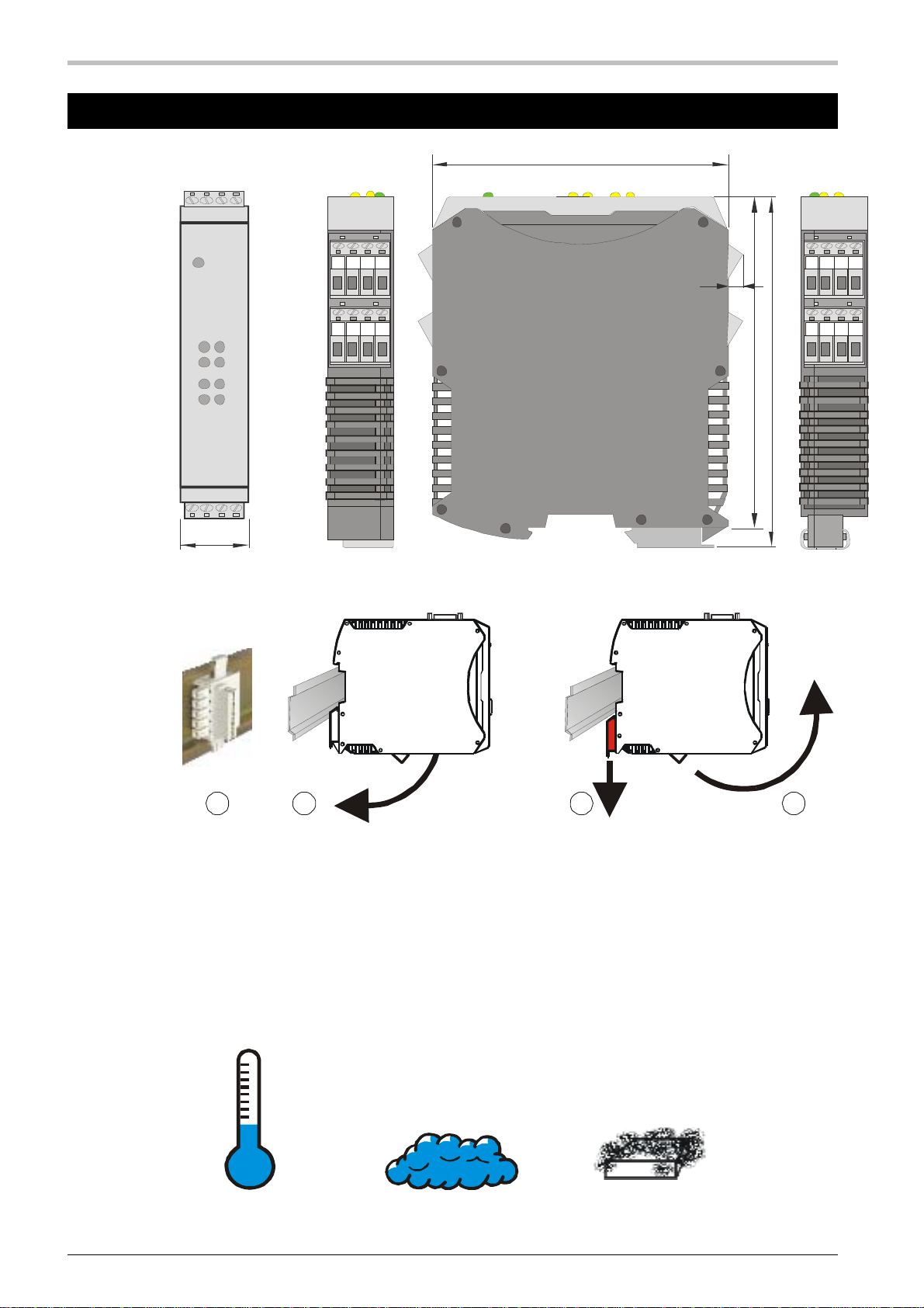
Fig. 2 Dimensions
1 1
22
click
Fig. 3 Assembly / Disassembly
The device is intended for vertical assembly on 35 mm top-hat rails according
to EN 50022. Devices of the HIMOD – family can be mounted directly next to
each other. A distance of at least 8 cm is to be maintained above and below the
device for assembly and disassembly.
For assembly, the device is simply to be swung in onto the top-hat rail from
above and audibly engaged. For disassembly, the foot bar is to be pulled down
with a screw driver and the device swung out upwards.
max. 55°C
min. -10°C
max.
95%
rel.
max.
Grad 2
degree 2
%
Fig. 4 Environmental Conditions

Assembly
HIMOD® HE 5820 Plug Connectors 9/17
The place of installation should be as free of vibrations, aggressive media
(such as acids, caustic solutions), liquids, dust or other suspended matter as
possible.
The module contains no parts subject to maintenance and does not need
to be opened by the customer.
The device may only be used in environments with the approved level of
protection.
The ventilation slits of the casing must not be covered.
In installations in which transient overvoltages can occur, for protection
the devices are to be fitted with additional surge suppressors or limiters.
Caution! The device contains ESD-endangered components.
Please observe the safety instructions (section 2).
To obtain contamination level 2 according to EN 61010-1, the device must
not be mounted below contactors or similar equipment, from which
conductive dusts or parts could trickle out.
3.1 Plug Connectors
The up to four-device connection terminals are designed pluggable. They are to
be plugged into the casing from above or below (audible locking). The
connectors are released by levering out with a screw driver. There are two
types available:
• Screwed terminals for conductor cross-sections up to 2.5 mm²
• Spring clamp terminals for conductor cross-sections up to 2.5 mm²
The connectors are only to be actuated with no load.
Screwed terminals are to be tightened with a tightening torque of
0.5 – 0.6 Nm.
With spring clamp terminals, rigid conductors and flexible
conductors with ferrules can be inserted directly into the terminal
point. The (orange) lever opener is to be actuated to release.
Contact protection: Terminal blocks not connected are to be left in the
slot.
Assembly
HIMOD® HE 5820 Front View and Indications 10/17
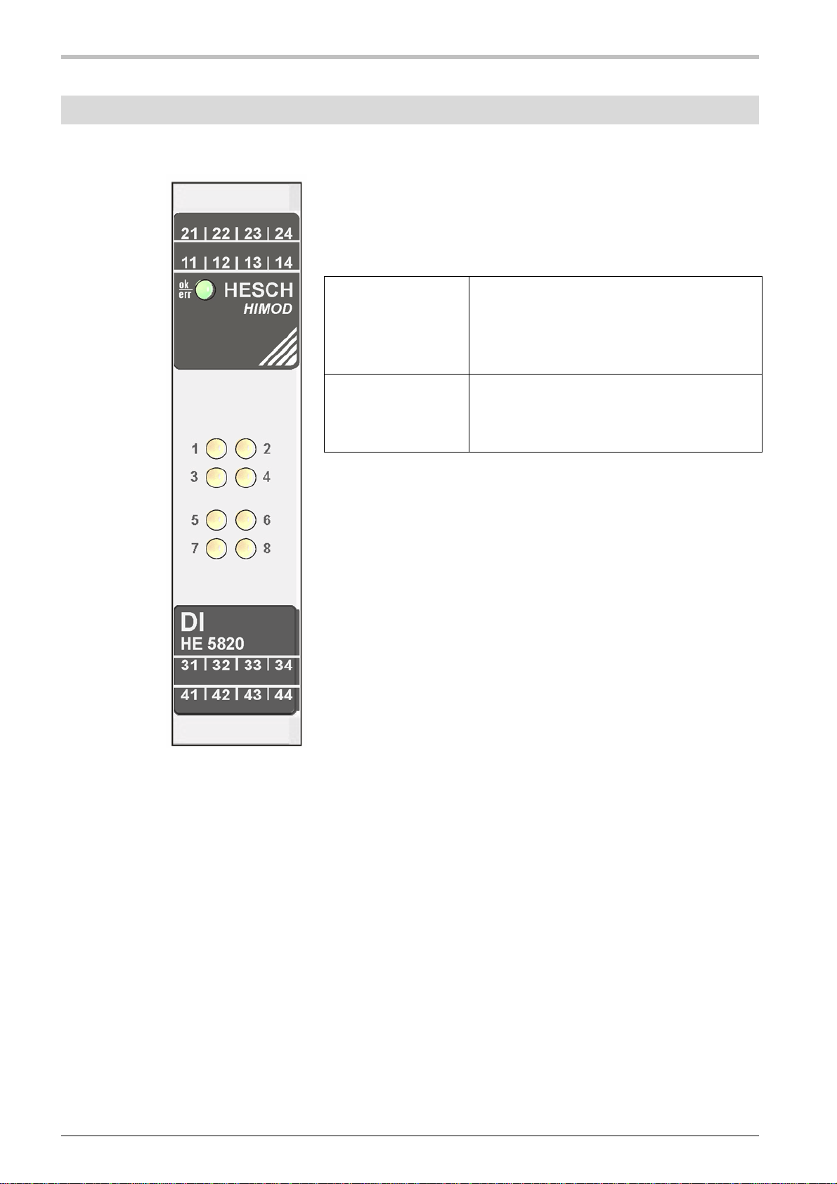
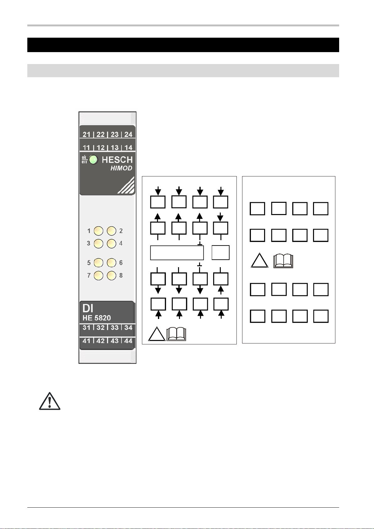
3.2 Front View and Indications
Fig. 5 HE5820 Front View
LED ok/err
On green
Flashing green
Flashing red
Off
Module OK
Configuration error
No voltage supply of the outputs
Voltage supply interrupted
LED 1 – 8
yellow
On
Off
Input ’ON’*
Input ’OFF’*
* with 'logical' 'ON'.
If the inputs have been inverted,
the inputs are not actively connected.
Electrical Connection
HIMOD® HE 5820 Connection Diagram 11/17
4 Electrical Connection
4.1 Connection Diagram
The 4-pole device plug connectors are used for the module function.
Fig. 6 Front View and Connector Pin Assignment
A faulty connection can lead to the destruction of the device!
1 2 3 4
!
Gnd
In
24VDC out
max. 200mA
Input
2421 22 23
1411 12 13
++
Input
++
4441 42 43
3431 32 33
5 6 7 8
1 2 3 4
!
Input
Input
5 6 7 8
2421 22 23
1411 12 13
++++
----
3431 32 33
4441 42 43
----
++++
Version PNP, NPN Version POT-free

Electrical Connection
HIMOD® HE 5820 Connection Specification 12/17
4.2 Connection Specification
The HE 5820 module exists with various internal circuits.
4.2.1 HE 5820 PNP Art. No.: HE58200000
HE 5820
+24V
+24V1
+24V2
GND
GND1
GND2
U1
IN1
U2
IN2
U3
IN3
U4
IN4
V
ersion PNP
+24V
+24V1
+24V2
GND
GND1
GND2
U5
IN5
U6
IN6
U7
IN7
U8
IN8
-F1
200mA
-S1 -S2 -S3 -S4
-F2
200mA
-S5 -S6 -S7 -S8
11 12 13 14 21 22 23 24 31 32 33 34 41 42 43 44
4.2.2 HE 5820 NPN Art. No.: HE58201000
HE 5820
+24V
+24V1
+24V2
GND
GND1
GND2
U1
IN1
U2
IN2
+24V
U3
IN3
U4
IN4
V
ersion NPN
+24V
+24V1
+24V2
GND
GND1
GND2
U5
IN5
U6
IN6
+24V
U7
IN7
U8
IN8
-F1
200mA
-S1 -S2 -S3 -S4
-F2
200mA
-S5 -S6 -S7 -S8
11 12 13 14 21 22 23 24 31 32 33 34 41 42 43 44
4.2.3 HE 5820 POT Art. No.: HE58203000
HE 5820
U1
+IN1+OUT1
-IN1-OUT1
U2
+IN2+OUT2
-IN2-OUT2
U3
+IN3+OUT3
-IN3-OUT3
U4
+IN4+OUT4
-IN4-OUT4
V
ersion potenzialfrei
U5
+IN5+OUT5
-IN5-OUT5
U6
+IN6+OUT6
-IN6-OUT6
U7
+IN7+O UT 7
-IN7-OUT7
U8
+IN8+OUT8
-IN8-OUT8
SPS D-OUT
21 11 22 12 23 13 24 14 41 31 42 32 43 33 44 34
The input impedance of 6.8 kis not shown in the examples.

Functional Description
HIMOD® HE 5820 Module Functions Parameterisation Table 13/17
5 Functional Description
The HE 5820 module provides the HIMOD bus coupler with eight inputs. The
functions of the module are parameterised in the device with the software tool
'SmartControl'.
Fig. 9 Screenshot Parameterisation of Module Functions
5.1 Module Functions Parameterisation Table
Fig. 10 Table of Module Parameters HE 5820
The parameters are the same for all variants of the HE 5820.
The module address is specified as Hex number.
5.1.1 Polarity and Debounce Time
With the parameter Plty, ’Polarity’ individual inputs are assigned inverted logic.
That means, that for process value ’On’ the channel LED is lit, but the input is
not actively switched on.
The debounce time is used for the safe forwarding of signals through
mechanical contacts and can also be used as interference suppression
measure in networks with interference signals.
Abbr. Description Mod
Addr. Value
default Meaning Range
Plty Polarity
[Input 1 ..8] 32
00000000 0 normal logic 1 bit per
input
1 inverted logic 1 bit per
input
Time Debouncing
time [ms] 33
10 Waiting time for
value change Valid for
all inputs
Functional Description
HIMOD® HE 5820 Meaning of the Module Status Information 14/17
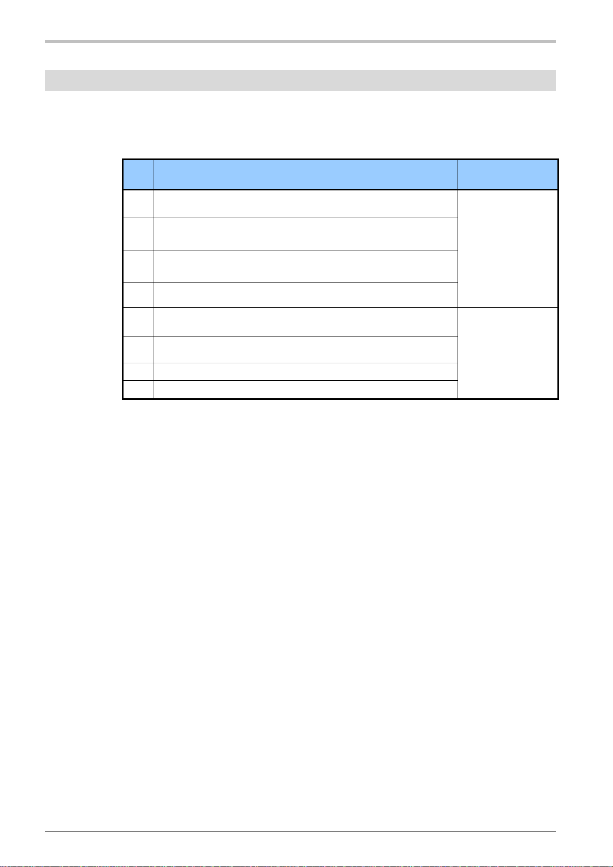
5.2 Meaning of the Module Status Information
The module status is depicted in the status byte. Every bit represents one item
of information. The meaning of the individual bits is to be taken from the table.
Bit Meaning
Remark
0 Bit is not used Is taken from the
module
1 Bit is not used
2 Bit is set, if an EEProm error is detected.
3 Bit is not used
4 No communication with the module (module has
failed) Is set by coupler
5 Module does not match configuration
6 Reserve
7 Reserve
SmartControl – Engineering Tool
HIMOD® HE 5820 Functionality of the 'SmartControl' Software 15/17
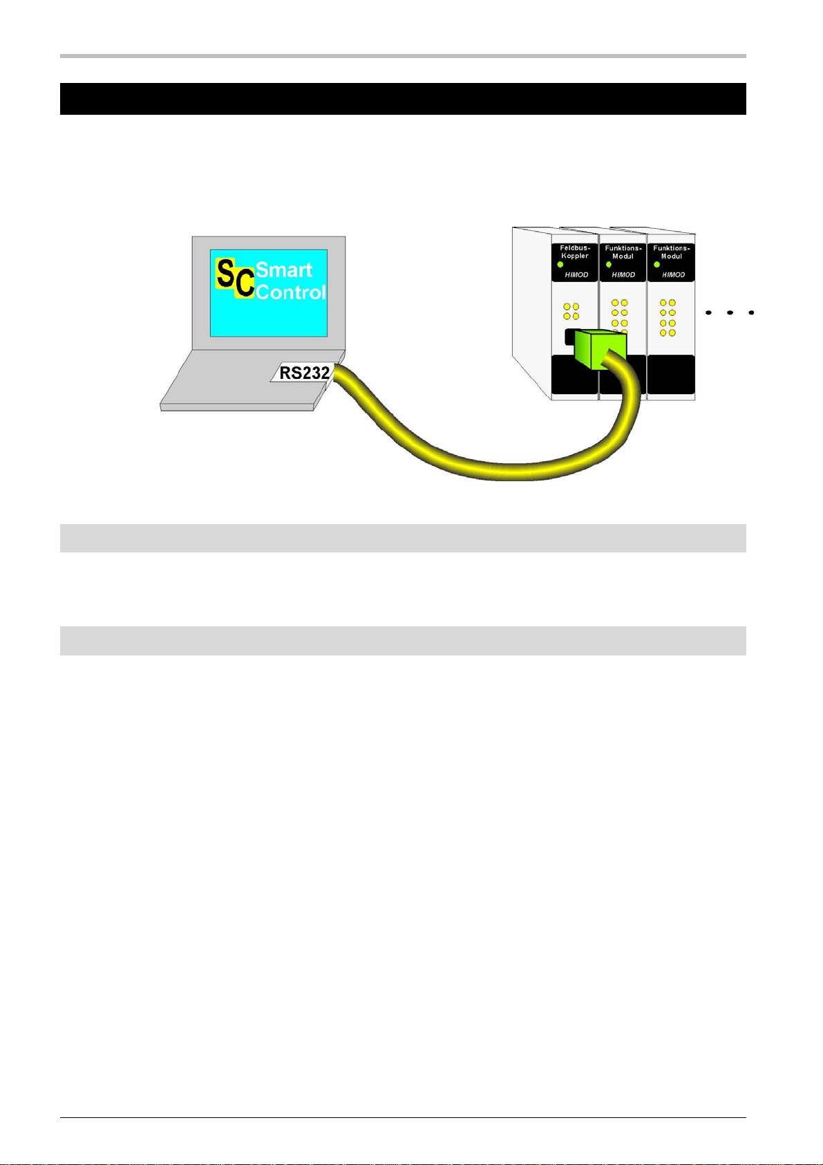
6 SmartControl – Engineering Tool
The engineering tool 'SmartTool' parameterises the function modules of an
HIMOD device and configures the system of the device. The physical
connection is established from a PC with RS232 port and a special cord to the
front port ’SmartPort’ on the field bus coupling module:
Fig. 11 'SmartControl' Connection
6.1 Order Numbers for SmartControl Components
SmartControlExpert Software 58510000
HIMOD Programming Adapter 58511000
6.2 Functionality of the 'SmartControl' Software
Setting of the parameters and configuration parameters
Download: Transmission of engineering to the module
Online Mode / Visualisation
Basic diagnostic function
Saving files, parameter setting
Print function
Online documentation / Help
Data acquisition and trend recording
Network- / multiple license
Assistant function

Technical Data
HIMOD® HE 5820 Environmental Conditions 16/17
7 Technical Data
7.1 Module Function
Module type: Input module for HIMOD systems
8 x 24 V DC in 2 switching groups
Version: Design as PNP, NPN or potential-free version
direct connection of 3-wire sensors
input specification according to IEC 1131
Sensor supply: Per channel there is a sensor supply of 24 V DC (±10 %)
available with a maximum current of 25 mA. 4 channels of a
group are protected together against short circuit with a 200 mA
multifuse.
Protection mechanisms: The inputs are protected against overvoltage with varistors
Input impedance: The input impedance per channel is 6.8 k
Indications: 1 LED green/red Module function and configuration
8 LED yellow Input status
7.2 Environmental Conditions
Ambient temperature: Operation: -10 .. 55°C
Storage: -25 .. 60°C
Transport: -25 .. 85°C
Influence: 0.05% / 10K
Humidity: KUF acc. to DIN 40040, max 95% rel. humidity
75% rel. humidity for yearly average, no dew formation
Ice formation: Not permitted
Air pressure: Operation and storage: 80 kPa to 106 kPa
Transport: 70 kPa to 106 kPa
Electrical isolation: The areas of supply voltage, field bus, logics and inputs are each
safely isolated galvanically from each other according to
EN 61010-1:
working voltage: 50 V
overvoltage category II
contamination level 2
Vibration: according to EN 60068-2-6, sinusoidal vibrations
Load: 5 g, 2 h per spatial direction
Impact: according to EN 60068-2-7
Load: 25 g over 11 ms, half sine wave
EMC: Emission: DIN EN 61000-6-3

Technical Data
HIMOD® HE 5820 Assembly and Connection 17/17
Immission: DIN EN 61000-6-2
Type of protection: Casing front: IP 20
Casing: IP 20
Connections: IP 20
7.3 Assembly and Connection
Assembly: on 35 mm top-hat rails according to EN 50022
locking with metal foot bar
position for use: vertical
Casing: material: polyamide PA 6.6
flammability class: V0 (UL 94)
dimensions: 22.5 x 99 x 117.5 mm (W x H x D)
weight: 125 g
Wiring technique: plug connectors, pluggable alternative can be ordered:
screwed terminals for conductor cross-sections of 0.2 to 2.5 mm²
(AWG 24–12)
spring clamp terminals for conductor cross-sections of 0.2 to 2.5
mm² (AWG 24–12)
Connection Supply and communications bus through T-Bus connector fitted
in the mounting rail.
Power consumption 7.5 V: 55 mA
Power consumption 24 V: 50 mA
Technical modifications reserved
This manual suits for next models
3
Table of contents
Other HESCH Control Unit manuals


Popular Control Unit manuals by other brands


Texas Instruments
Texas Instruments VCA5807 user guide

FuzzDog
FuzzDog BrassMaster V2 quick start guide

Cleveland
Cleveland P-DR-CC Specifications

Endress+Hauser
Endress+Hauser RNF22 operating instructions

TQ
TQ TQMa93xxLA Preliminary user's manual

Metso
Metso 7150 Installation maintenance and operating instructions


