HESCH HE 5760 User manual

# 372449 | Version 3.2
Filter Control
HE 5760
Operating instructions
(Translation of Original German version)

2
HE 5760 Operating Instructions
# 372449| Version 3.2
Imprint
HESCH Industrie-Elektronik GmbH
Boschstraße 8
31535 NEUSTADT, GERMANY
Phone: +49 5032 9535–0
Fax: +49 5032 9535-99
Internet: www.hesch-automation.com
Email: [email protected]
District Court Hanover
HRB 111184
VAT.-Id. No. DE813919106
General Management
Werner Brandis
Published by:
HESCH Industrie-Elektronik GmbH, Documentation Department
Copyrights
© Copyright 2021 HESCH Industrie-Elektronik GmbH. All rights reserved.
The content including pictures and the design of these operating
instructions are subject to copyright protection and other laws for the
protection of intellectual property. The modification of the contents of this
operating instructions is prohibited. In addition, this content may not be
copied, distributed, modified or made available to third parties for
commercial purposes.

HE 5760 Operating Instructions
# 372449 | Version 3.2
3
Document history
Date / Version
Description / Author
04.07.2014 / 3.0
Document history added. Version no. added. Layout change title page,
imprint added. Section 3.5 amended): Description changed. Section 1.3
amended. HE 1149 Image updated. Chapter 1.3.4 (HE 5410) Picture
updated.
18.01.2019 / 3.1
System expansion: I&C interface (Modbus / Profibus) / Bg
15.12.2020 / 3.2
Document transferred to new layout, new parameters, chapter 12
Central dust monitoring added / Bg

4
HE 5760 Operating Instructions
# 372449| Version 3.2
TABLE OF CONTENTS
1LEGAL PROVISIONS................................................................................................................................... 6
2SAFETY INFORMATION ............................................................................................................................. 7
2.1 SYMBOLS AND BASIC SAFETY INSTRUCTIONS...................................................................................................... 7
2.2 SIGNAL WORDS............................................................................................................................................ 7
2.3 SAFETY IN THE INDIVIDUAL OPERATING PHASES................................................................................................... 8
3TECHNICAL DATA.................................................................................................................................... 10
4MOUNTING ............................................................................................................................................ 11
4.1 DIMENSIONS ............................................................................................................................................. 11
5SYSTEM OVERVIEW ................................................................................................................................ 12
5.1 SYSTEM COMPONENTS ................................................................................................................................ 12
5.1.1 Master control HE 5760................................................................................................................. 12
5.1.2 HE 5725 ......................................................................................................................................... 13
5.1.3 HE 1149 ......................................................................................................................................... 13
5.1.4 Differential pressure transmitter HE 5410 .................................................................................... 14
5.2 FILTER SYSTEM........................................................................................................................................... 14
6DISPLAY AND OPERATING ELEMENTS ..................................................................................................... 15
7ELECTRICAL COMMISSIONING ................................................................................................................ 16
7.1 ELECTRICAL CONNECTION HE 5760............................................................................................................... 17
7.1.1 Local operation through control signals........................................................................................ 18
7.2 ELECTRICAL CONNECTION HE 5725............................................................................................................... 19
7.3 CAN NETWORK CONFIGURATION................................................................................................................... 20
7.3.1 CAN address assignment............................................................................................................... 20
7.3.2 CAN address setting on HE 5725 ................................................................................................... 21
7.3.3 CAN termination............................................................................................................................ 21
7.3.4 Termination on HE 5760 and HE 5725........................................................................................... 22
7.4 SYSTEM START-UP ...................................................................................................................................... 23
8OPERATION ............................................................................................................................................ 24
8.1 ACTUAL VALUE IMAGE................................................................................................................................. 24
8.2 ALARM SCREENS ........................................................................................................................................ 25
8.3 CHAMBER CONTROL.................................................................................................................................... 26
8.4 INFO SCREEN ............................................................................................................................................. 26
8.5 COMMUNICATION STRUCTURE...................................................................................................................... 27
9PARAMETERISATION .............................................................................................................................. 28
9.1 SMARTTOOL.............................................................................................................................................. 28
9.2 PARAMETER TABLE ..................................................................................................................................... 29
9.3 DESCRIPTION OF THE PARAMETERS ................................................................................................................ 31
9.3.1 System description ........................................................................................................................ 31
9.3.2 On site service ............................................................................................................................... 32
9.3.3 Interfaces....................................................................................................................................... 32
9.3.4 Valve control ................................................................................................................................. 33
9.3.5 Overall cleaning (cleaning process)............................................................................................... 35
9.3.6 Chamber control............................................................................................................................ 36
9.3.7 Operating hours ............................................................................................................................ 36
9.3.8 Service ........................................................................................................................................... 37
9.3.9 Autostart / Timeout....................................................................................................................... 37
9.3.10 Passwords...................................................................................................................................... 37
9.3.11 Measuring ranges.......................................................................................................................... 38

HE 5760 Operating Instructions
# 372449 | Version 3.2
5
9.3.12 Error evaluation............................................................................................................................. 38
9.3.13 Dust monitoring............................................................................................................................. 39
9.3.14 dp regulation ................................................................................................................................. 41
10 ERROR MESSAGES............................................................................................................................... 43
10.1 SYSTEM START-UP ...................................................................................................................................... 43
10.2 ALARM SCREENS ........................................................................................................................................ 44
10.2.1 Sensor error ................................................................................................................................... 44
10.2.2 Misprint ......................................................................................................................................... 45
10.2.3 Valve control Bus error .................................................................................................................. 45
10.2.4 Valve error..................................................................................................................................... 46
10.2.5 Valve control tank pressure sensor error....................................................................................... 46
10.2.6 Valve control Tank pressure error (sensor is OK)........................................................................... 46
11 COMMUNICATION.............................................................................................................................. 47
11.1 MASTER (HE 5760) -SLAVE (HE 5725) COMMUNICATION .............................................................................. 47
11.2 DATA DIRECTION PROCESS CONTROL TO HE 5760 ............................................................................................ 48
11.3 DATA DIRECTION HE 5760 TO PROCESS CONTROL ............................................................................................ 50
11.4 DIAGNOSIS HE 5760 ON PROCESS CONTROL ................................................................................................... 53
12 CENTRAL DUST MONITORING (APPLIES FROM SOFTWARE VERSION 2.10).......................................... 55
12.1 RESET OF DUST VALVES................................................................................................................................ 56
13 MAINTENANCE AND SERVICE.............................................................................................................. 57
14 GLOSSARY........................................................................................................................................... 58

6
HE 5760 Operating Instructions
# 372449| Version 3.2
1 Legal Provisions
Manufacturer
HESCH Industrie-Elektronik GmbH, Boschstraße 8, 31535 NEUSTADT | GERMANY
Intended use
The HE 5760 is a master-slave control for the cleaning process of industrial dust
extraction systems.
The expansion to a complete cleaning control system is carried out with the HE 5725
valve controllers, each of which controls 12 valves. Up to 48 valve controllers can be
centrally controlled as CAN slaves by the HE 5760. The valves are assigned to so-
called filter chambers. The control is set to the existing number of chambers and
valves using the parameter menu. Parameterisation can also be carried out with the
PC software 'SmartTool' via the USB interface.
The HE 5760 control unit is located in a front-mounted housing with membrane
keypad and graphic display and is designed for installation in control cabinets. Local
operation at the control cabinet with switchgear and signal lamps that are connected
directly is possible.
The device can be operated within the operating and environmental conditions
approved in these operating instructions without impairing its safety.
The manufacturer is not liable for improper use and any resulting personal injury or
material damage; the risk is borne solely by the user. Failure to comply with the above
criteria for intended use will result in the expiry of the warranty and liability for the
device.
Personnel qualification
All work on the differential pressure transducer may only be carried out by qualified
electricians with sufficient knowledge in the field of electrical engineering.
Device Safety
The device has been constructed and tested in accordance with VDE 0411 / EN 61010-1 and
has left the factory in perfect safety condition. To maintain this condition and ensure safe
operation, the user must follow all instructions and warnings in this quick guide.
HE 5760 Operating Instructions
# 372449 | Version 3.2
7
2 Safety Information
2.1 Symbols and Basic Safety Instructions
This chapter contains important safety regulations and notes. To protect against personal
injury and material damage, it is necessary to read this chapter carefully before working with
the device.
Symbols used
The following symbols are used in this manual. All safety instructions have a uniform structure.
Personal Injury Warning!
The severity of the danger is indicated by the respective signal word.
Explosive region warning sign!
High Voltage Warning!
Warning of material damage caused by electrostatic charge!
Property Damage Warning!
Note!
Identifies possible malfunctions and indicates optimum operating
conditions.
2.2 Signal words
DANGER!
Indicates an imminently hazardous high risk situation, which, if not avoided, will result in death
or serious injury.
WARNING!
Indicates a potentially hazardous medium risk situation, which, if not avoided, could result in
death or serious injury.
CAUTION!
Indicates a hazardous low risk situation, which, if not avoided, could result in minor or
moderate injury.

8
HE 5760 Operating Instructions
# 372449| Version 3.2
2.3 Safety in the individual operating phases
When installing the device and during operation, the following safety instructions must be
observed.
Danger of Electrocution!
Before working on the device, switch off all power supplies used. The
electrical cables must be laid according to the respective national
regulations (in Germany VDE 0100). The measuring cables must be laid
separately from the power lines. The connection between the connector
for the functional earth (in the respective equipment carrier) and a
protective earth must be established.
Danger of Electrocution!
Any interruption of the protective earth in the equipment carrier can result
in the device becoming a hazard. Intentional interruptions are not
permitted. If there is a suspicion that it is no longer possible to operate
the device safely, it must be shut off and secured against being
unintentionally switched on.
Danger of Electrocution!
Do not open the device when it is connected to the voltage! When
opening the devices or removing covers and parts, live parts may be
exposed. Connection points can also be live!
Attention!
The device must never be put into operation even if damage is
recognisable.
Attention!
During installation, commissioning, maintenance and troubleshooting,
observe the accident prevention regulations applicable to your system,
e.g. DGUV Regulation 3 "Electrical installations and equipment".
Attention!
Clean dirty contacts with oil-free compressed air or ethyl alcohol and a lint-
free cloth.
Warning of material damage caused by electrostatic charge!
Observe the safety measures according to BS EN 61340-51/-3 to avoid
electrostatic discharge!

HE 5760 Operating Instructions
# 372449 | Version 3.2
9
Power Connection!
The electrical cables must be laid according to the respective national
regulations (in Germany VDE 0100). The measuring cables must be laid
separately from the power lines.
Troubleshooting!
At the beginning of troubleshooting, all possible sources of faults on
additional devices or supply lines (measuring lines, wiring, downstream
devices) should be taken into consideration. If the fault is not found after
checking these points, we recommend sending the device to the supplier.
Decommissioning!
Switch off the power supply on all poles if the device is to be
decommissioned. Secure the device against being unintentionally
switched on!
If the device is linked to other devices and/or equipment, consider the
impacts and take appropriate precautions before switching it off.
10
HE 5760 Operating Instructions
# 372449| Version 3.2
3 Technical data
Subject to technical changes without notice!
Technical Data
Supply:
-24 V( 22…26 V AC)
-galvanically separated
-0.3 A typical
-5 A maximum
Display:
-graphic LC display
-Resolution: 128 × 64 7938
-display area: 66 × 33 mm
-Colour: yellow green
LEDs
-operation: green
-Cleaning active: yellow
-Alarms: red
Keys:
-menu operation: ESC, F1, F2, ENTER
-navigation and value entry: LEFT, RIGHT, UP, DOWN
Processor:
-Fujitsu MB96F348
-544 kB Flash / 280 kB RAM
-1 MB flash for parameters and data
-Real-time clock optional
Ports
-CAN interface, galvanically isolated, 50 kBit/s
control interface: Modbus RTU, Profibus
Inputs:
-5 Digital inputs 24 V DC, galvanically isolated, for local
operation: Operation on the control cabinet with keys and
indicator lights
-2 analogue inputs 4...20 mA for system pressure and
differential pressure, accuracy: 0.1%
Outputs:
4 digital outputs 24 V DC, 1A, short-circuit proof, for local
operation
Housing
Switch panel housing
Dimensions:
196 × 126 × 40 mm (W × H × D)
Excerpt:
166 × 96 mm (W × H)
IP protection class:
-IP 65 Front
-IP 20 Rear
Electrical connections
USB interface connector type B,
Screw terminals for supply, CAN, local operation,
measurement
Interference immunity:
DIN EN 61000-6-2 and DIN EN 61326-1
Emitted interference
DIN EN 61000-6-3 and DIN EN 61326-1
Environmental Weather Conditions
Operation:
-10…+55 °C
Storage:
-25…+60 °C
Transport
-25…+85 °C
Ambient humidity:
75% rel. humidity, no condensation
HE 5760 Operating Instructions
# 372449 | Version 3.2
11
4 Mounting
The ambient temperature at the installation point must not exceed the
permissible temperature for nominal use specified in the technical data.
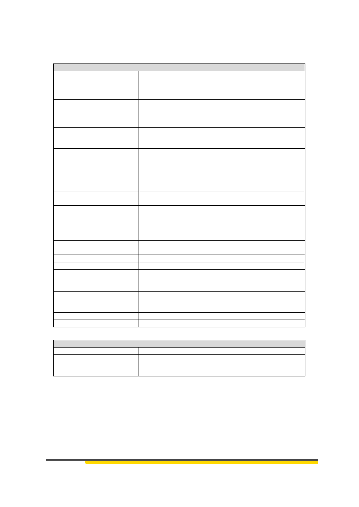
4.1 Dimensions
The HE 5760 is a panel-mounted unit with the following dimensions:
Figure 1 HE 5760 Dimensions
Scope of Delivery
HE 5760 Premium
Operating instructions
Note!
Check the delivery upon receipt for completeness and for visible defects.
In the event of a complaint, contact our HESCH Service immediately (see
chapter 13 Maintenance and Service).
12
HE 5760 Operating Instructions
# 372449| Version 3.2
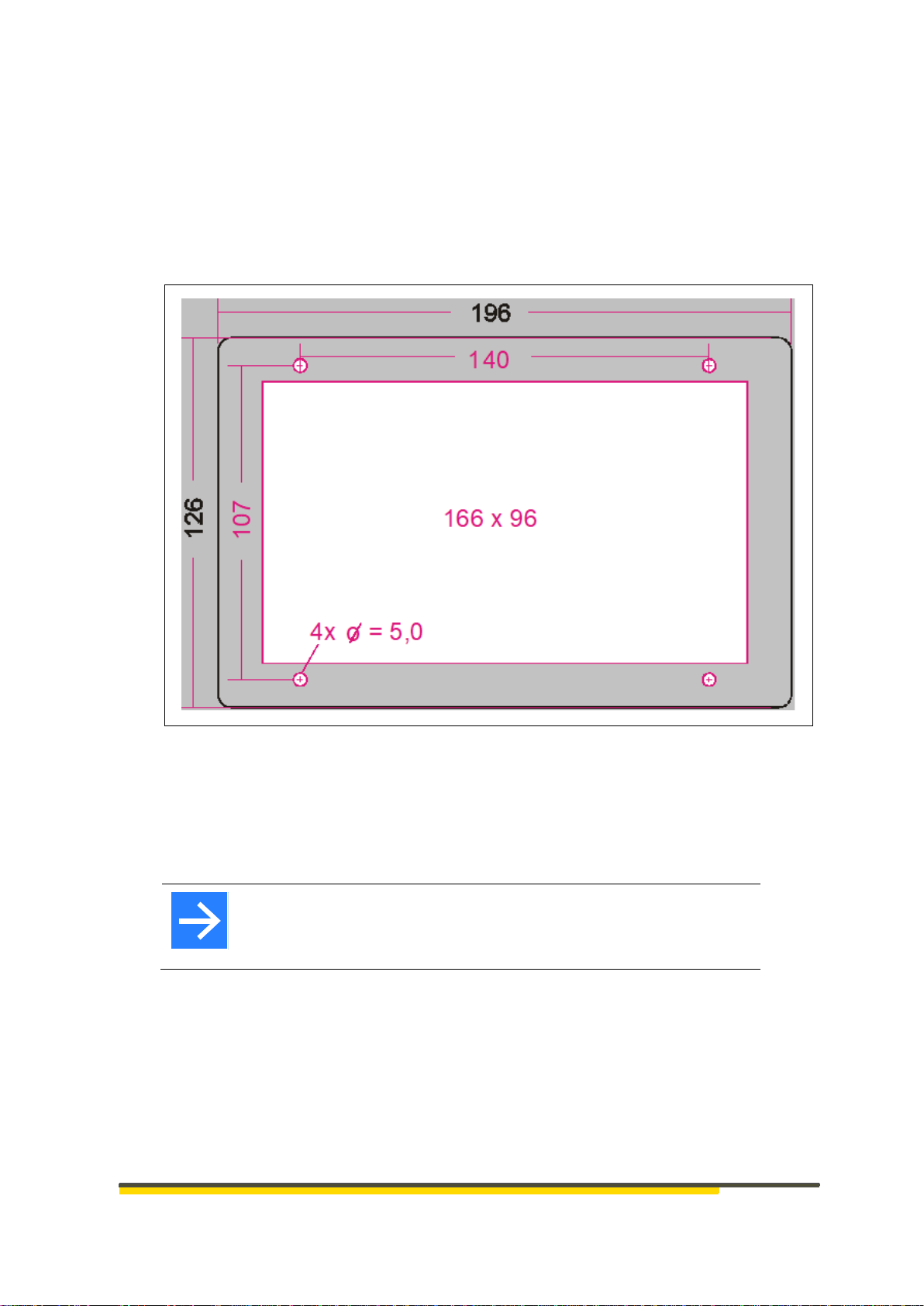
5 System overview
HE5725 HE 5725 HE 5725 HE 5725
CAN
Figure 2 System overview HE 5760 / HE 5725
5.1 System components
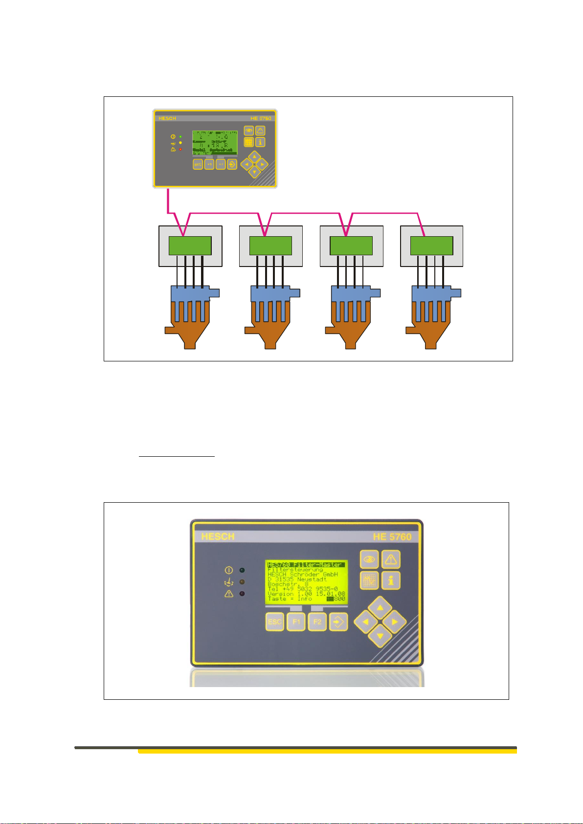
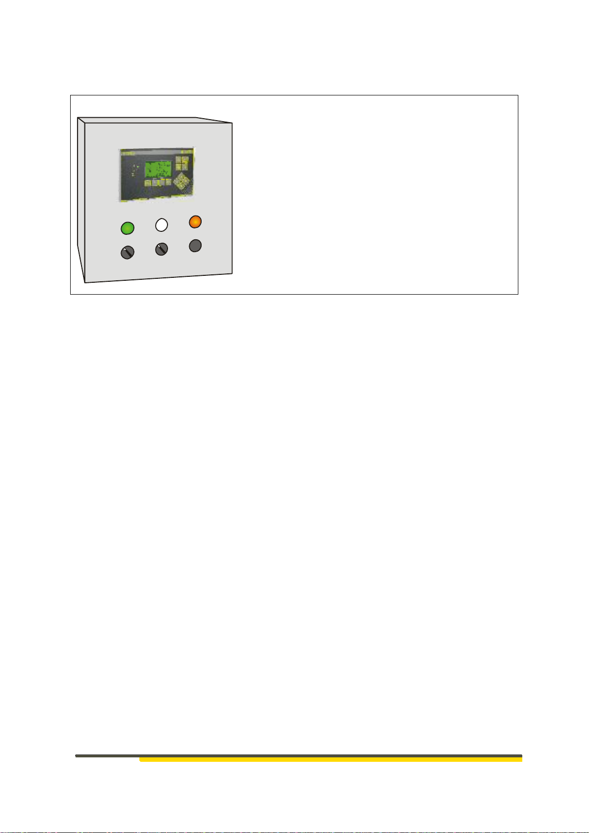
5.1.1 Master control HE 5760
Central control of the filter system
To be connected:
CAN line,
Pressure sensor for system pressure and differential pressure
Keys and indicator lights for local operation, if desired.
Figure 3 HE 5760
HE 5760 Operating Instructions
# 372449 | Version 3.2
13
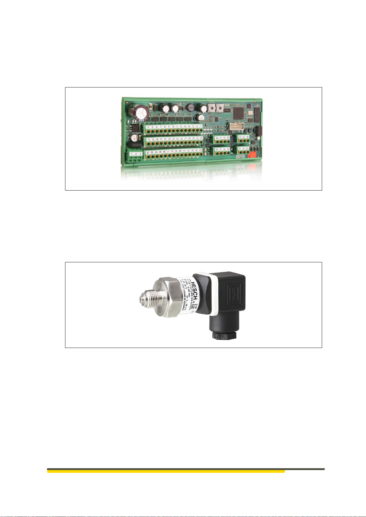
5.1.2 HE 5725
Valve control as CAN slave
12 valves are connected directly as well as the pressure sensors of the local pressure
tanks
Figure 4 HE 5725
5.1.3 HE 1149
Used to measure the compressed air at the central supply 'system pressure' and at
the local pressure tanks
Measurement range 1.5…10 bar.
Figure 5 HE 1149
14
HE 5760 Operating Instructions
# 372449| Version 3.2
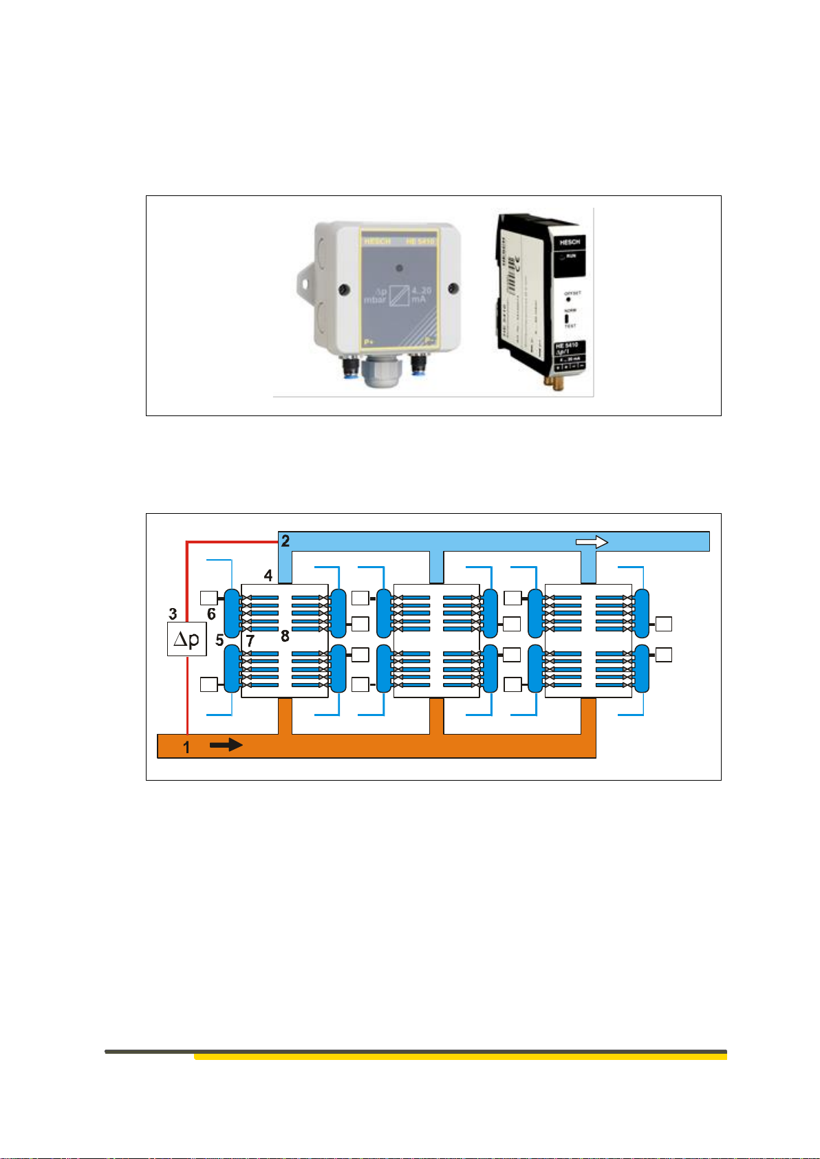
5.1.4 Differential pressure transmitter HE 5410
Differential pressure is measured between clean gas and raw gas side
Measured value is used as a measure of the contamination of the filter system
Measuring range 0...100 mbar
Figure 6 HE 5410
5.2 Filter system
P
P
Figure 7 Filter sketch
1 Raw gas
2 Clean gas
3 Differential pressure measurement raw gas clean gas
4 Chamber as spatial unit of the filter elements
5 Local pressure tanks
6 Pressure measurement at the local pressure tank
7 Valves for compressed air cleaning of the filter elements
8 Filter elements

HE 5760 Operating Instructions
# 372449 | Version 3.2
15
6 Display and operating elements
Figure 8 Display and Operating Elements HE 5760
Symbols:
Display Elements Meaning
LED indicators
Operation
The operating voltage is present and the control unit is ready for operation.
Cleaning active
The status of the control is thus visible, even if no valve is activated at the
moment.
Alarms present
The alarm key can be used to view current alarms and the alarm list.
Command and control keys
Exit the current menu without changing the value
Context menu keys, meaning is shown in the lowest text line of the display.
Selection of the current value. Acceptance of the changed value.
Hot Keys
Function keys for system operation
The function keys call up the operating and display options of normal
operation. By pressing several times, more screens become visible.
See also section 8 Operation.
Navigation keys
Line selection, value change for selected values
-Backlight brightness
-Page switching for longer lists
Decimal position for value representation

16
HE 5760 Operating Instructions
# 372449| Version 3.2
7 Electrical commissioning
Before switching on the device, observe the following points:
Connect the cable firmly to the glands. The power supply must correspond to the voltage
indicated on the nameplate.
The unit may only be operated when installed.
The temperature limitations specified for the use of the device must be complied with before
and during operation.
The protective conductor connection in the corresponding equipment rack must be conductively
connected to the protective conductor.
Danger of Electrocution!
Electrical installation must only be carried out when the power is
disconnected.
Warning of material damage caused by electrostatic charge!
Observe the safety measures according to DIN EN 61340-51/-3 to avoid
electrostatic discharge!
Note!
Work on the electronic parts may only be carried out by qualified
personnel.
Figure 9 HE 5760 Rear with electrical connections
Analogue input 1
Analogue input 2
Option: Modbus / Profibus
connection

HE 5760 Operating Instructions
# 372449 | Version 3.2
17
7.1 Electrical connection HE 5760
Supply 24 V DC Supply
1
24 V DC
2
GND
3
FE Functional Earth
CAN communication
4
CAN-H
5
CAN-L
6
CAN -GND
Termination / Bus termination switchable
Digital Out 24 V DC status signals
7
Operation = green LED
8
Cleaning = yellow LED
9
Malfunction = red LED
10
Pulse
11
Out-GND
Analogue In 4...20 mA Pressure
measurement
18
Filter dp +
Analogue input 1
19
4...20 mA -
20
System p +
Analogue input 2
21
4...20 mA -
Digital In 24 V DC control signals
12
Local/Remote
13
Acknowledge
14
Start
15
Stop
16
Post-Cleaning
17
IN-GND
18
HE 5760 Operating Instructions
# 372449| Version 3.2
7.1.1 Local operation through control signals
123
456
Figure 10 Example of the possible use of the control signals
1 Operation
2 Cleaning
3 Malfunction
4 Local/Remote
5 Start/Stop
6 Acknowledge

HE 5760 Operating Instructions
# 372449 | Version 3.2
19
7.2 Electrical connection HE 5725
Figure 11 Electrical connection HE 5725
Supply 24 V DC Supply
1
+ 24 V DC 1A
2
GND
3
PE
Valves 1 to 6, 24 V DC
4
Valve 1 +
18
Valve 1 GND
32
Valve 1 PE
5
Valve 2 +
19
Valve 2 GND
33
Valve 2 PE
6
Valve 3 +
20
Valve 3 GND
34
Valve 3 PE
7
Valve 4 +
21
Valve 4 GND
35
Valve 4 PE
8
Valve 5 +
22
Valve 5 GND
36
Valve 5 PE
9
Valve 6 +
23
Valve 6 GND
37
Valve 6 PE
Pressure 1
16
+ 24 V DC Out
30
Sensor 1 GND
44
PE
IN
Out
CAN Connection
46
50
CAN-H
47
51
CAN-L
48
52
CAN-GND
49
53
Umbrella
Valves 7 to 12, 24 V DC
10
Valve 7 +
24
Valve 7 GND
38
Valve 7 PE
11
Valve 8 +
25
Valve 8 GND
39
Valve 8 PE
12
Valve 9 +
26
Valve 9 GND
40
Valve 9 PE
13
Valve 10 +
27
Valve 10 GND
41
Valve 10 PE
14
Valve 11 +
28
Valve 11 GND
42
Valve 11 PE
15
Valve 12 +
29
Valve 12 GND
43
Valve 12 PE
Pressure 2
17
+ 24 V DC Out
31
Sensor 2 GND
45
PE
20
HE 5760 Operating Instructions
# 372449| Version 3.2
7.3 CAN network configuration
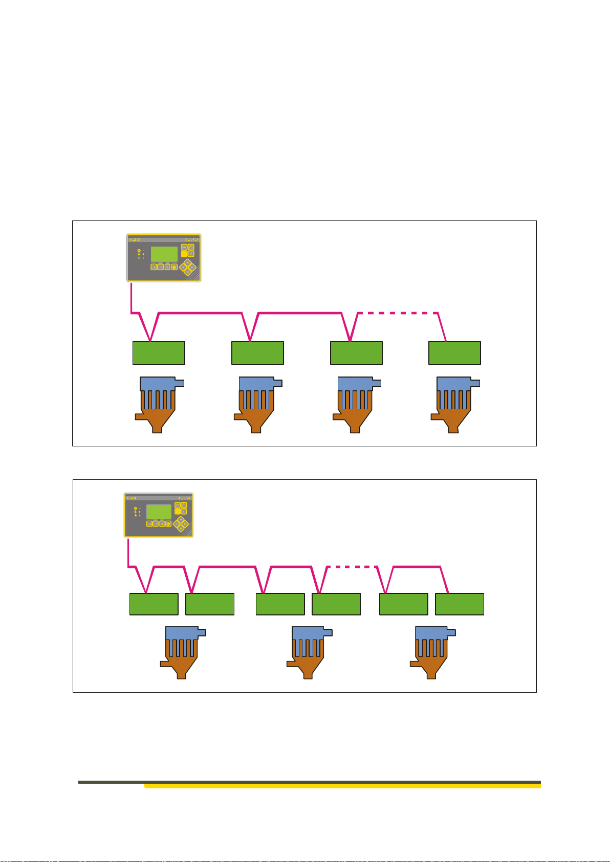
7.3.1 CAN address assignment
Each device in the CAN network is addressed with its CAN node number. The assignment of
the CAN addresses must comply with certain rules.
The HE 5760 control unit does not require a CAN address.
With the HE 5725 valve controls, a distinction is made between:
one HE 5725 per chamber, consecutive numbering, 1, 2, 3, ... 48
two HE 5725 per chamber, split numbering, 1, 25, 2, 26, ... 24, 48
HE 5725 HE5725 HE 5725 HE 5725
CAN
1 2 3 . . . 48
Figure 12 CAN numbering 1 slave per chamber
HE 5725 HE 5725 HE 5725HE 5725 HE 5725 HE 5725
CAN
125 26..2.. 24 48
Figure 13 CAN numbering 2 slaves per chamber
Table of contents
Other HESCH Control Unit manuals


Popular Control Unit manuals by other brands


Anval
Anval SG Series Installation & maintenance manual

IFM Electronic
IFM Electronic Ecomat100 CR1083 PDM360 NG installation instructions

Data Video
Data Video CCU-200 instruction manual

Koganei
Koganei F Series manual

Jetter
Jetter JX3-PS1 user manual

OSF
OSF SAUNA exclusiv 9kW Installation and operating instructions


