HESCH HE 5710 User manual
HE 5710 / HE 5711
µP-magnetic valve control
Operating manual
Translation of the original operating manual
(Original version German)

3Operating manual HE 5710 / HE 5711
Version 1.3 • Item number #371814 • 04.12.2019
Imprint
HESCH Industrie-Elektronik GmbH
Boschstraße 8
D-31535 Neustadt
Germany
Phone +49 (0) 5032 9535-0
Fax +49 (0) 5032 9535-99
Internet: www.hesch.de
E-Mail: info@hesch.de
District court Hanover
HRB 111184
VAT No.: DE813919106
Management:
Walter Schröder, Werner Brandis
Publisher:
HESCH Industrie Elektronik GmbH, Documentation Department
Copyrights
© Copyright 2019 HESCH Industrie-Elektronik GmbH. All rights reserved. The content
including pictures and the design of this manual are subject to copyright protection and
other laws for protection of intellectual property. The dissemination or alteration of the
content of this manual is prohibited. Moreover, these contents may not be copied, dis-
seminated, altered or made accessible to third parties for commercial reasons.

Operating manual HE 5710 / HE 5711 4
Version 1.3
Table of content
1 Foreword. . . . . . . . . . . . . . . . . . . . . . . . . . . . . . . . . . . . . . . . . . . . . . . . . . . . . . . . . .5
1.1 Information regarding the usage of these operating instructions. . . . . . . . . . . . . . . . . . . . . . . . 5
1.2 Legal provisions. . . . . . . . . . . . . . . . . . . . . . . . . . . . . . . . . . . . . . . . . . . . . . . . . . . . . . . . . . . . . 6
2 Safety information . . . . . . . . . . . . . . . . . . . . . . . . . . . . . . . . . . . . . . . . . . . . . . . . . .7
2.1 Symbols and basic safety information . . . . . . . . . . . . . . . . . . . . . . . . . . . . . . . . . . . . . . . . . . . . 7
2.2 Safety during the individual phases of operation . . . . . . . . . . . . . . . . . . . . . . . . . . . . . . . . . . . . 8
3 Device description . . . . . . . . . . . . . . . . . . . . . . . . . . . . . . . . . . . . . . . . . . . . . . . . .11
3.1 Overview . . . . . . . . . . . . . . . . . . . . . . . . . . . . . . . . . . . . . . . . . . . . . . . . . . . . . . . . . . . . . . . . . 11
3.2 Display and control elements. . . . . . . . . . . . . . . . . . . . . . . . . . . . . . . . . . . . . . . . . . . . . . . . . . 12
3.3 Technical data . . . . . . . . . . . . . . . . . . . . . . . . . . . . . . . . . . . . . . . . . . . . . . . . . . . . . . . . . . . . . 13
4 Installation . . . . . . . . . . . . . . . . . . . . . . . . . . . . . . . . . . . . . . . . . . . . . . . . . . . . . . .14
5 Electrical commissioning . . . . . . . . . . . . . . . . . . . . . . . . . . . . . . . . . . . . . . . . . . .15
5.1 Safety information . . . . . . . . . . . . . . . . . . . . . . . . . . . . . . . . . . . . . . . . . . . . . . . . . . . . . . . . . . 15
5.2 Supply voltage . . . . . . . . . . . . . . . . . . . . . . . . . . . . . . . . . . . . . . . . . . . . . . . . . . . . . . . . . . . . . 16
5.3 Connection diagram. . . . . . . . . . . . . . . . . . . . . . . . . . . . . . . . . . . . . . . . . . . . . . . . . . . . . . . . . 17
5.4 Inputs . . . . . . . . . . . . . . . . . . . . . . . . . . . . . . . . . . . . . . . . . . . . . . . . . . . . . . . . . . . . . . . . . . . . 18
5.5 Valves . . . . . . . . . . . . . . . . . . . . . . . . . . . . . . . . . . . . . . . . . . . . . . . . . . . . . . . . . . . . . . . . . . . 18
5.6 Commands . . . . . . . . . . . . . . . . . . . . . . . . . . . . . . . . . . . . . . . . . . . . . . . . . . . . . . . . . . . . . . . 18
6 Setting-up . . . . . . . . . . . . . . . . . . . . . . . . . . . . . . . . . . . . . . . . . . . . . . . . . . . . . . . .19
7 Declaration of conformity . . . . . . . . . . . . . . . . . . . . . . . . . . . . . . . . . . . . . . . . . . .20
8 Maintenance and service . . . . . . . . . . . . . . . . . . . . . . . . . . . . . . . . . . . . . . . . . . .21
8.1 Notes . . . . . . . . . . . . . . . . . . . . . . . . . . . . . . . . . . . . . . . . . . . . . . . . . . . . . . . . . . . . . . . . . . . . 21

Chapter 1 Foreword
5Operating manual HE 5710 / HE 5711
Version 1.3
1 Foreword
1.1 Information regarding the usage of these operating instruc-
tions
Structure
Target group
These operating instructions are intended for qualified electricians that will install, wire, commission
and put the magnetic valve control HE 5710 / HE 5711 into operation.
Document history
Chapter 1 Foreword
Information on chapter structure, document history, intended use and device
safety.
Chapter 2 Safety information
Important safety information regarding the Differential Pressure Regulator.
Chapter 3 Device description
Description of the magnetic valve control, control elements and technical spec-
ifications.
Chapter 4 Installation
Dimensions of the device and scope of delivery.
Chapter 5 Electrical commissioning
Connection of supply voltage and signals.
Chapter 6 Setting-up
Performing setting-up on the device.
Chapter 7 Declaration of conformity
Chapter 8 Maintenance and service
Information regarding control operations and disposal.
Date / version Description
12/2013 / 1.0 First Creation
04/2014 / 1.1 Page 2 (footer): Corrected item number. Chapter 7: Added declaration of con-
formity. Chapter 3 (Fig. 3.1 + 3.2), 3.3, Chapter 5.2 + 5.3: Changed value for
wide-range power supply (100 – 240 VAC)
09/2019 / 1.2 Chapter 2: device marking adapted
12/2019 / 1.3 Chapter 2.2: device marking explanation completed.
Chapter 3.3: Typing error in device marking corrected
Bilingual name plates added.

Chapter 1 Foreword
Operating manual HE 5710 / HE 5711 6
Version 1.3
1.2 Legal provisions
Manufacturer
HESCH Industrie-Elektronik GmbH, Boschstraße 8, D-31535 Neustadt, Germany
Intended use
The magnetic valve control HE 5710 / HE 5711 serves to clean industrial filtration plant.
The control unit can be operated within the usage and ambient conditions stated in this
manual without causing any safety risks.
The manufacturer is not liable for improper usage and the resulting personnel injuries or
damage; the risk lies entirely with the operator. Failure to comply with the above mentioned
criteria regarding intended use may void the warranty – the manufacturer cannot be held li-
able for damage to the device in this case.
Personnel qualification
Only qualified electricians with the appropriate knowledge in the field of electrical engineering are
allowed to conduct any work on the magnetic valve control.
Device safety
The device was built and tested in accordance with VDE 0411 / EN 61010-1 and has left the fac-
tory in an operationally safe condition. In order to maintain this condition and to ensure safe opera-
tion, the user has to follow the instructions and warnings contained in this manual, see chapter 2
"Safety information" on page 7.

Chapter 2 Safety information
7Operating manual HE 5710 / HE 5711
Version 1.3
2 Safety information
2.1 Symbols and basic safety information
This chapter contains important safety provisions and information. In order to protect against per-
sonnel injury and damage, it is necessary to carefully read this chapter before working with the de-
vice.
Used symbols
The following symbols are used in this manual. All safety information notes are structured in a uni-
form manner.
Warning of personnel injury!
The severity of the danger is indicated by the respective signal word, see page 8.
Warning of explosive atmosphere!
Warning of dangerous electrical voltage!
Warning of material damage due to electrostatic charging!
Warning of material damage!
Note!
Indicates possible malfunctions and provides information regarding optimal oper-
ating conditions.
Chapter 2 Safety information
Operating manual HE 5710 / HE 5711 8
Version 1.3
Signal words
DANGER!
Indicates an immediate danger with high risk that will result in death or serious injury if not avoided.
WARNING!
Indicates a possible danger with medium risk that may result in death or serious injury if not
avoided.
CAUTION!
Indicates a danger with low risk that might result in slight or moderate injury if not avoided.
Structure of warning notes
All warning notes in these operating instructions are structured in a uniform manner. The pictogram
designates the type of danger.
2.2 Safety during the individual phases of operation
The following safety information must be observed when installing the device and during operation.
SIGNAL WORD!
An informative text describes the danger and suggests how it can be avoided.
Danger of electric shock!
Disconnect the power supply before working on the device. Install the electrical
lines in accordance with the respectively applicable local regulations (VDE 0100
in Germany). Lay the measuring lines separately from the power lines. Produce a
connection between the protective ground connection (in the respective device
carrier) and a protective ground.
Danger of electric shock!
Any interruption of the protective ground in the device carrier may cause the de-
vice to become dangerous. Deliberate interruptions are not permissible. If it can
be assumed that safe operation is no longer possible, then the device shall be
put out of commission and be secured against unintended operation or re-activa-
tion.
Danger of electric shock!
Do not open the device under voltage! When opening the devices or removing
covers and parts, live parts may become exposed. Connecting points may also
be live!
Caution!
The device may not be put into operation when there is visible damage on the
device.
Chapter 2 Safety information
9Operating manual HE 5710 / HE 5711
Version 1.3
Caution!
Observe the accident prevention regulations applicable to the system, such as
BGV A 3 "Electrical Systems and Equipment" during installation, commissioning,
maintenance and troubleshooting.
Caution!
Clean soiled contacts using oil-free compressed air or spirit and a lint-free cloth.
Material damage due to electrostatic charging!
Observe the safety measures according to DIN EN 61340-51/-3 in order to pre-
vent electrostatic discharging!
The original packaging protects against any electrostatic discharge.
Only transport the device in its original packaging
During assembly observe all regulations for protection against electrostatic dis-
charges.
Electrical connection!
Install the electrical lines in accordance with the respectively applicable local reg-
ulations (VDE 0100 in Germany).
Lay the measuring lines separately from the power lines.
Produce a connection between the protective ground connection (in the respec-
tive device carrier) and a protective ground.
The cable shielding belongs to the measurement earth.
The effects of interference fields can be prevented through use of twisted and
screened measuring lines.
The respective connection diagrams / connection designs for the devices apply.
Explosion protection!
This device (the version with the Makrolon housing) is suitable for operation in
Explosion Zone 22 with the lid closed (where an explosive atmosphere may arise
due to electrically conductive dusts).
Prior to opening the device, one must ensure that there are no explosive ambient
conditions, such as dust formation.
The special regulations governing operation in an Ex-area must be observed.
Blowing of a fuse!
First determine the causes for the failure and remove them.
Only use fuses which have the same specification as the original type as a re-
placement.
Repaired fuses or short circuiting are not permissible.

Chapter 2 Safety information
Operating manual HE 5710 / HE 5711 10
Version 1.3
The following provisions must be observed:
Attach the cables to the cable glands correctly in order to retain the protection class.
Operation with an opened lid is not permissible.
The tightness of the hose screw connections/glands, for example for ∆p measurement or
measuring hose cleaning, must be checked.
Provide unneeded housing bores with locking bolts.
It is only permitted to clean the housing with wet cleaning agents in order to avoid static
charging.
It is required to clean the device in order to prevent increased dust formation.
The device is marked with:
II3D Device category: use in zone 22 for dust during normal operation
Ex Designates an electrical equipment
tc Type of ignition protection: protection by housing
IIIC Dust group: conductive dusts
T135°C Temperature class: maximum permissible surface temperature
Dc Device protection level: use in zone 22 for dust
IP65 Protection class: dust-proof, scoop-proof
Troubleshooting!
When beginning to troubleshoot, all possible sources of error regarding additional
equipment or cables (measuring lines, wiring, slave devices) should be taken into
consideration. If no error source can be found after examining these points, we
recommend to send the device to the supplier.
Decommissioning!
Disconnect the power supply entirely if the device is to be decommissioned. Se-
cure the device against inadvertent operation!
If the device is interconnected with other devices and/or equipment, the effects of
the deactivation should be considered prior to disconnecting the device and the
appropriate precautions should be taken beforehand.
Chapter 3 Device description
11 Operating manual HE 5710 / HE 5711
Version 1.3
3 Device description
3.1 Overview
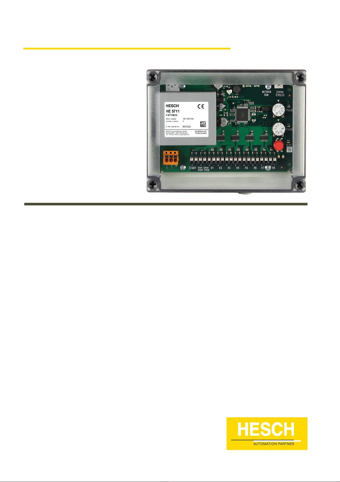
Fig. 3.1: An overview (taking the 5710 as an example)
A. Type designation
B. Display and control elements
C. Connection compartment
A
B
C

Chapter 3 Device description
Operating manual HE 5710 / HE 5711 12
Version 1.3
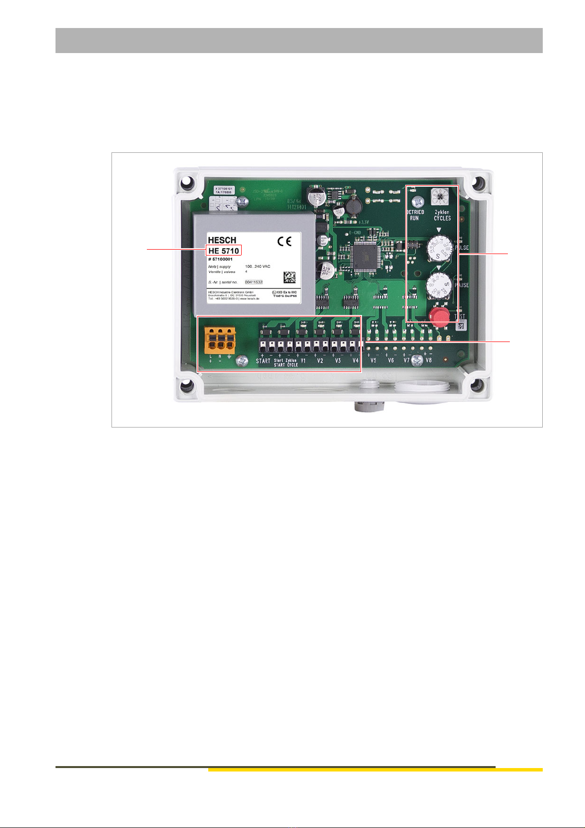
3.2 Display and control elements
Fig. 3.2: Display and control elements (on the 5711 as an example)
Symbols Meaning
1. RUN
LED, green
Lights up if the operating voltage is being applied and the processor is active
2. CYCLES
Coding switch
Determines the number of cycles (1 – 9). The setting 0 deactivates the cyclic
cleaning
3. PULSE
LED, yellow
Lights up during the actuation period (pulse) of the valves
Potentiometer for pulsing period setting between 0.02 and 1.2 seconds
4. PAUSE
LED, yellow
Lights up in the pause leading up to actuation of the next valve. The condition
of the control unit is recognisable, also for a longer pause time.
Potentiometer for pause time setting between 1 and 270 seconds
5. Button TEST
The first press of the button starts the pulse and pause of the next valve.
The second press of the button interrupts the pause of the active valve or
starts the next valve.
Longer pressing of the button (for longer than 2 seconds) starts cleaning for
the set cycles. If the number of cycles is 0, cleaning will continue until the but-
ton is pressed again.
1
2
3
4
5

Chapter 3 Device description
13 Operating manual HE 5710 / HE 5711
Version 1.3
3.3 Technical data
Subject to technical changes.
Technical data
Intended use: The magnetic valve control serves to clean industrial filtration plant
Supply voltage: 100 – 240 VAC, 50 – 60 Hz
24 VDC ±10% (option)
Power consumption: 30 VA, own power consumption about 3 W
LEDs: HE 5710: 4 for valve control unit, red
HE 5711: 8 for valve control unit, red
RUN, green
PULSE, yellow
PAUSE, yellow
TEST, green
Control elements: Button TEST: the next valve is actuated
PULSE, setting the pulse period
Potentiometer from 0.02 and 1.2 seconds
PAUSE, setting the pause time
Potentiometer from 1 and 270 seconds
CYCLES: setting the cycles
Rotary coded switch 0 - 9; 0 deactivates the function
Inputs: START: start cleaning (contact closed)
START CYCLE: cyclic cleaning (trigger signal)
Switchable with a potential-free contact or a semiconductor switch,
"Active Low"
Valve outputs: HE 5710: 1 – 4
HE 5711: 1 – 8
Valve voltage: 24 VDC ±10%
Valve current: 1 A for a pulse period of ≤ 1s and a pause time ≥ the pulse period
The outputs are short-circuit-proof
Fuse: Glass fuse 5 × 20 mm, 2 A, slow blow
Electrical connections: Vertical cage spring release terminals
Operating temperature: -20°C … +50°C / -20°C … +40°C in Ex-area
Explosion protection: ATEX II 3D Ex tc IIIC T135° Dc, IP65, Zone 22
(version with the housing)
Versions: Construction on a standardised rail support; 165 mm × 111 mm
(W × H)
A dustproof Makrolon housing (IP65) with a transparent lid, with a
M25 × 1.5 thread and two M32 × 1.5 threads for metric screw con-
nections
Openings should be closed, if necessary with screw plugs, to make
the device dustproof (IP65)
An M32 screw plug is in the scope of delivery of the HE 5710
Housing dimensions: 180 mm × 130 mm × 78 mm (W × H × D)
Connectors:
(option)
1 × M25 screwed cable gland
2 × M32 screwed cable gland
Multiple sealing inserts and locking bolts
Height of the cable gland: 40 mm
Chapter 4 Installation
Operating manual HE 5710 / HE 5711 14
Version 1.3
4 Installation
The ambient temperature at the installation position may not exceed the permissible temperature
for rated use listed in the data sheet. The device may be installed in areas subject to the EX ATEX
Zone 22 Explosion Class. The special provisions should be observed, see chapter 2.2 "Safety dur-
ing the individual phases of operation" on page 8.
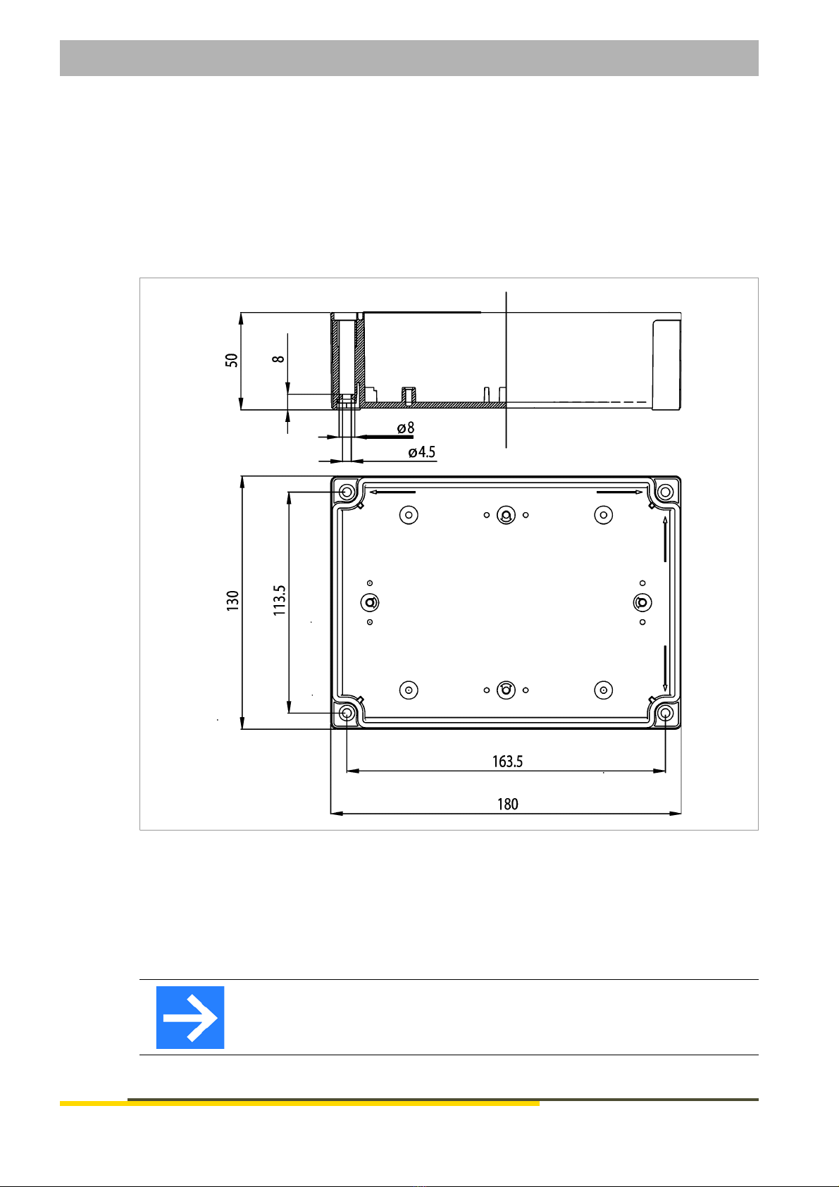
Dimensions
Fig. 4.1: Dimensions
Scope of delivery
HE 5710 / HE 5711
Operating manual
Note!
After receiving the delivery, check it for completeness and obvious defects. In
case of a complaint, immediately contact your local HESCH representative.

Chapter 5 Electrical commissioning
15 Operating manual HE 5710 / HE 5711
Version 1.3
5 Electrical commissioning
Mind the following points prior to turning on the device:
Firmly connect the cables to the cable glands. The supply voltage must match the specifi-
cations on the type plate.
The device may only be operated in a closed state.
The temperature limitations specified for use of the device have to be observed before and
during operation.
The protective ground connection in the appropriate device carrier has to be conductively
connected to the protective ground.
5.1 Safety information
Danger of electric shock!
Only perform the electrical installation in a dead-voltage state.
Material damage due to electrostatic charging!
Observe the safety measures according to DIN EN 61340-51/-3 in order to pre-
vent electrostatic discharging!
Note!
Only qualified specialists may work on the electronics.

Chapter 5 Electrical commissioning
Operating manual HE 5710 / HE 5711 16
Version 1.3
5.2 Supply voltage
Fig. 5.1: Supply voltage
1. Loosen the screws on the housing cover and remove the cover.
2. Read the supply voltage value off the type plate (for example 100 – 240 VAC or 24 VDC mains
voltage).
3. Connect PE conductors.
100 - 240 VAC
24 VDC
LNPE
+-

Chapter 5 Electrical commissioning
17 Operating manual HE 5710 / HE 5711
Version 1.3
5.3 Connection diagram
Fig. 5.2: Connection diagram (on the 5711 as an example)
Terminal Description
L (+) Supply voltage L, 100 – 240 VAC, or (+) 24 VDC
N (-) Supply voltage L, 100 – 240 VAC, or (-) 24 VDC
PE Potential to ground
+ START Input for cleaning start (+), Active Low
- START Input for cleaning start (GND)
+ START CYCLE Input for cyclic cleaning (+), Active Low
- START CYCLE Input for cyclic cleaning (GND)
+ V1 Output of valve 1 (+24 V DC)
- V1 Output of valve 1 (GND)
+ V2 Output of valve 2 (+24 V DC)
- V2 Output of valve 2 (GND)
+ V3 Output of valve 3 (+24 V DC)
- V3 Output of valve 3 (GND)
+ V4 Output of valve 4 (+24 V DC)
- V4 Output of valve 4 (GND)

Chapter 5 Electrical commissioning
Operating manual HE 5710 / HE 5711 18
Version 1.3
The terminals V5 (+ and -) to V8 (+ and -) only for HE 5711.
5.4 Inputs
The magnetic valve control has 2 inputs: START and START CYCLE. The inputs are internally
supplied with + 24 VDC and are active when they are switched to (-) with a potential-free contact.
5.5 Valves
5.6 Commands
Steady-state operation: connect the terminals START (+ and -).
Cyclic operation: connect the terminals START CYCLE (+ and -) (trigger signal).
+ V5 Output of valve 5 (+24 V DC)
- V5 Output of valve 5 (GND)
+ V6 Output of valve 6 (+24 V DC)
- V6 Output of valve 6 (GND)
+ V7 Output of valve 7 (+24 V DC)
- V7 Output of valve 7 (GND)
+ V8 Output of valve 8 (+24 V DC)
- V8 Output of valve 8 (GND)
Terminal Description
Connection: HE 5710 on terminals V1 (+ and -) to V4 (+ and -)
HE 5711 on terminals V1 (+ and -) to V8 (+ and -)
Valve type: 24 VDC, a maximum of 1 A
Common potential: -
Switched output: +
The outputs are short-circuit-proof.

Chapter 6 Setting-up
19 Operating manual HE 5710 / HE 5711
Version 1.3
6 Setting-up
Number of valves
The number of valves is determined automatically by the control unit. Recognised valves are dis-
played by lit up LEDs.
Number of full cleaning cycles
Using the coding switch CYCLES, set the number (1 – 9). The setting 0 deactivates cyclic cleaning.
The cleaning process for the set cycles is started by means of trigger signal to the START CYCLE
terminals (+ and -) .
Pulsing period of the valves
Setting using the PULSE potentiometer between 0.02 and 1.2 seconds.
Pause time of the valves
Setting using the pausing potentiometer PAUSE between 1 and 270 seconds.

Chapter 7 Declaration of conformity
Operating manual HE 5710 / HE 5711 20
Version 1.3
7 Declaration of conformity
You will find the declaration of conformity on www.hesch.de

Chapter 8 Maintenance and service
21 Operating manual HE 5710 / HE 5711
Version 1.3
8 Maintenance and service
8.1 Notes
Maintenance, repair
The device has to be cleaned regularly in order to avoid increased dust formation on the device.
Disposal
Recycle metals and plastics. Electrical and electronic components should be collected separately
and be disposed of accordingly. Properly dispose of printed circuit boards.
Service
HESCH Industrie-Elektronik GmbH
Boschstraße 8
D-31535 Neustadt
Germany
Phone: + 49 (0) 5032 9535-90
This manual suits for next models
2
Table of contents
Other HESCH Control Unit manuals


Popular Control Unit manuals by other brands

GEM
GEM R639 operating instructions

Bang & Olufsen
Bang & Olufsen BEOLINK VIDEO Handbook

Metabolic Devices
Metabolic Devices 2win How to begin

Eaton
Eaton Cutler-Hammer Durant PRESIDENT Series Installation and operation manual

Siemens
Siemens MVS661 N Series Mounting instructions

Kaysun
Kaysun KWF-140 HT ACS owner's manual


Temptime
Temptime EDGE M-300 user guide

Visonic
Visonic PowerMax Pro GSM installation instructions

Whelen Engineering Company
Whelen Engineering Company WeCan Series installation guide

SIGMA TEK
SIGMA TEK PW 022 instruction manual

Festo
Festo CPX-E-EP Instructions & Operating

Metrohm
Metrohm 900 Manual - Short Instructions