Endress+Hauser Cerabar T PMP135 User manual

KA 198P/00/a6/03.03
52015486
ENDRESS+HAUSER
CERABAR T
ENDRESS+HAUSER
CERABAR T
ENDRESS+HAUSER
CERABAR T
Cerabar T
PMP135
pPrzetwornik ciœnienia
w wykonaniu higienicznym
ePressure transducer for
hygienic applications
dDrucktransducer für
hygienische Prozesse
Hauser+Endress
The Power of Know How

2 Endress+Hauser

p Spis treœci
Uwagi dotycz¹ce
bezpieczeñstwa 4
Identyfikacja przyrz¹du 6
Monta¿ 7
Pod³¹czenie elektryczne,
Wyjœcie analogowe
(wersja z wtykiem) 8
Pod³¹czenie elektryczne,
Wyjœcie analogowe
(wersja z przewodem) 9
Pod³¹czenie elektryczne,
Wyjœcie sygnalizacyjne 10
Rozmieszczenie
elementów obs³ugi 11
Ustawianie zera 13
Ustawianie punktu
prze³¹czania i histerezy 14
Charakterystyka punktu
prze³¹czania i histerezy 15
Warunki pracy 16
Dokumentacja
uzupe³niaj¹ca 17
e Contents
Notes on Safety 4
Device Identification 6
Mounting 7
Electrical Connection,
Analogue Output with
Plug 8
Electrical Connection,
Analogue Output with
Cable 9
Electrical Connection,
Switch Output 10
Location of
Operating Elements 11
Adjusting the Zero Point 13
Setting Switch Point and
Hysteresis 14
Diagram of Switch Point and
Hysteresis 15
Operating Conditons 16
Supplementary
Documentaions 17
d Inhalt
Sicherheitshinweise 4
Geräte-Identifikation 6
Montage 7
Elektrischer Anschluß,
Analogausgang mit
Stecker 8
Elektrischer Anschluß,
Analogausgang mit Kabel 9
Elektrischer Anschluß,
Schaltausgang 10
Lage der Bedienelemente 11
Nullpunkt einstellen 13
Schaltpunkt und
Hysterese einstellen 14
Diagramm Schaltpunkt
und Hysterese 15
Einsatzbedingungen 16
Ergänzende
Dokumentation 17
Endress+Hauser 3

p Uwagi dotycz¹ce
bezpieczeñstwa
Cerabar T jest przeznaczony
do pomiarów ciœnienia absolut-
nego i wzglêdnego gazów, pa-
ry i cieczy. Niew³aœciwe u¿ycie
mo¿e prowadziæ do powstania
zagro¿eñ zwi¹zanych z kon-
kretnym zastosowaniem.
Monta¿, pod³¹czenie, urucho-
mienie, obs³uga i konserwacja
przetwornika mog¹ byæ wyko-
nywane tylko przez wykwalifi-
kowany i uprawniony personel.
Nale¿y œciœle przestrzegaæ za-
leceñ zawartych w niniejszej
instrukcji i karcie katalogowej
TI 372P, stosownych norm
i wymogów prawnych oraz
zaleceñ zawartych w posia-
danych certyfikatach.
Uwaga dla PMP135 z wyjœ-
ciem sygnalizacyjnym: W celu
unikniêcia zak³óceñ elektrycz-
nych, nale¿y stosowaæ wy-
³¹cznie obci¹¿enie indukcyjne.
e Notes on Safety
The Cerabar T is designed for
measuring absolute and
gauge pressure of gases,
vapours and liquids. If used
incorrectly it is possible that
application related dangers
may arise.
The Cerabar T may be
installed, connected,
commissioned, operated and
maintained by qualified and
authorised personnel only,
under strict observance of this
operating instruction and the
Technical Information TI 372P,
any relevant standards, legal
requirements, and, where
appropriate, the certificate.
Note for PMP135 with switch
output: To prevent RF
interference, always operate
inductive loads with direct
protective circuit.
d Sicherheitshinweise
Der Cerabar T dient der
Absolut- und Überdruck-
messung in Gasen, Dämpfen,
Flüssigkeiten.
Bei unsachgemäßem Einsatz
können Gefahren von ihm
ausgehen.
Das Gerät darf nur von quali-
fiziertem und autorisiertem
Fachpersonalunter strenger
Beachtung dieser Betriebs-
anleitung und der Techni-
schen Information TI 372P, der
einschlägigen Normen, der
gesetzlichen Vorschriften und
der Zertifikate eingebaut,
angeschlossen, in Betrieb
genommen und gewartet
werden.
Hinweis für PMP135 mit
Schaltausgang: Um Funk-
störungen zu vermeiden,
induktive Lasten nur mit
direkter Schutzschaltung
betreiben.
4 Endress+Hauser

p Identyfikacja przyrz¹du
e Device Identification
d Geräte-Identifikation
ENDRESS+HAUSER
CERABAR T
ENDRESS+HAUSER
CERABAR T
PMP 135- ########
A1 = Pg 11, IP 65
A2 = /
1
2
NPT, IP 65
A3 = M 12x1, IP 65/IP 68
A4 = 5 m, IP 68
SER No.
5m
p
ENDRESS+HAUSER
CERABAR T
ENDRESS+HAUSER
CERABAR T
IP 65 (1) (rd) + (2) (wt) –
Endress+Hauser 5

p
A1G = 0...1 bar, 0...100 kPa
R4T = 0...500 psi a
...
F = Clamp
G = Clamp 1 ...1
1234
12
/" /",
DN 10..20, AISI 316L
"/",
DN 25..40, AISI 316L
H = Clamp 2", DN 50
AISI 316L
...
M=G1A
,Version
AISI 316L
À
N= G1A
,Version
AISI 316L
Á
S=SMS1 "
12
/
AISI 316L
1 = bez/without/ohne
C, 2 = Protokó³/Protocol/Protokoll
0 = 4…20 mA
D = 4...20 mA, ATEX II 1/2G EEx ib IIC T6
1 = 4…20 mA, ATEX II 2G EEx ib IIC T6
5 = 4...20 mA, ATEX II 3G EEx nA II T6
2 = SP ON../SP OFF..
3 = SP ON../SP OFF.., ATEX II 3G EEx nA II T6
M
Ø55
Ø27,5
Ø34
M
Ø50,5
Ø43,5
M
Ø64
Ø56,5
M
M
G1A
2
7
M
G1A
23
M Membrana
Membrane
Membran
Ø
17,2 mm
À
Á
6 Endress+Hauser

p Monta¿
•Dzia³anie przetwornika
PMP135 jest niezale¿ne
od jego pozycji pracy.
•W celu ochrony przy³¹cza
procesowego i celi pomia-
rowej przed uszkodzeniem,
os³onê ochronn¹ nale¿y
zdj¹æ dopiero bezpoœrednio
przed monta¿em.
•Przetwornik PMP135 nale¿y
montowaæ w analogiczny
sposób jak manometr. Zale-
cenia monta¿owe s¹ w tym
przypadku identyczne.
•Po zamontowaniu przetwor-
nika, upewniæ siê, ¿e woda
nie dostaje siê do obudowy
elektroniki.
e Mounting
•The function of the
PMP135 transducer is
independent of mounting
orientation.
•To protect the process
connection and pressure
diaphragm from damage,
the protective cover should
be removed just before
installation only.
•The pressure transducer is
to be mounted like a
manometer. The guidelines
are identical.
•When installing, ensure that
no water enters the housing.
d Montage
•Die Funktion des Druck-
transducers PMP135 ist
nahezu unabhängig von der
Einbaulage.
•Zum Schutz des Prozess-
anschlusses und der
Druckmembran darf die
Schutzkappe erst kurz vor
dem Einbau entfernt werden.
•Der Drucktransducer ist
nach den gleichen
Richtlinien wie ein
Manometer zu montieren.
•Beim Einbau ist darauf zu
achten, daß kein Tropf-
wasser in das Gehäuse
eindringen kann.
Endress+Hauser 7

p Pod³¹czenie elektryczne
Wyjœcie analogowe
e Electrical Connection
Analogue Output
d Elektrischer Anschluß
Analogausgang
maks. 1,5 mm2
Pg 11
/
12NPT
(AWG 16)
(SWG 17)
45
2
3
3
2
1
+PE
–
!
1
ENDRESS+HAUSER
CERABAR T
PMP131-########
SER No.
p
4…20 mA
IP 65 (1) (rd) + (2) (wt) –
– U = 12…30 V DC
– Ex: U 26 V, I 100 mA, P≤≤ ≤
0,8 W
Wtyk z d³awikiem Pg 11 / 1/2NPT
12 V 30 V
0
860
R/
B
Ω
8 Endress+Hauser

dLinia ciœnienia referencyjnego
Nie zatykaæ!
Chroniæ przed dostawaniem siê wody!
eReference air tube
Do not close! Protect from water!
dReferenzluft- Zuführung
Nicht verschließen!
Vor Wasser schützen!
+= czerwony/red/rot
–= bia³y/white/weiß
PE = zielony/green/grün
+
PE
–
– U = 12…30 V DC
–Ex:U 26V,
I 100 mA,
P
≤
≤
≤0,8 W
– U = 12…30 V DC
–Ex:U 26V,
I 100 mA, P
≤
≤≤
0,8 W
ENDRESS+HAUSER
CERABAR T
PMP 131- ########
SER No.
p
4…20 mA
IP 65 (1) (rd) + (2) (wt) –
-
+
Przewód / Cable / Kabel
∅5.8 mm2
PUR
Wtyk M 12x1
Endress+Hauser 9

p Pod³¹czenie elektryczne
Wyjœcie sygnalizacyjne
e Electrical Connection
Switch Output
d Elektrischer Anschluß
Schaltausgang
R: obci¹¿enie zewn., Pmax =6W
external load, Pmax =6W
externe Last, Pmax =6W
!
maks. 1,5 mm
2
Pg 11
/
12NPT
(AWG 16)
(SWG 17)
1
4
2
3
ENDRESS+HAUSER
CERABAR T
PMP 131- ########
SER No.
p
SP ON … / SP OFF …
IP 65 (1) (rd) + (2) (wt) –
– U = 18…32 V DC
3
2
1
PE
PE
L– L–
L+ L+
3
2
1
R
R
U = 18…32 V DC
ENDRESS+HAUSER
CERABAR T
PMP 131- ## # # # ###
SER No.
p
4…20 mA
IP 65 (1) (rd) + (2) (wt) –
Wtyk z d³awikiem Pg 11 / 1/2NPT Wtyk M 12x1
10 Endress+Hauser

p Rozmieszczenie
elementów obs³ugi
e Location of Operating
Elements
d Lage der Bedienelemente
ÀÀ
pOdkrêciæ nakrêtkê
po³¹czeniow¹
eUnscrew
coupling nut
dÜberwurfmutter
abschrauben
pNie obracaæ z³¹cza À!
eDo not turn the
mounting boss À!
dSteckersockel Ànicht
drehen!
Wtyk z d³awikiem
Pg 11 / 1/2NPT
Wtyk M 12x1
Endress+Hauser 11

≤2,5 mm
2– 3+
1+
+
–
2–1+
12
3
123
pUstawianie punktu prze³¹czania
eSwitch point setting
dSchaltpunkteinstellung
pWyjœcie analogowe
eAnalogue output
dAnalogausgang
pWyjœcie sygnalizacyjne
eSwitch output
dSchaltausgang
pWkrêtak do regulacji
eScrewdriver for adjusting
dWerkzeug zur Einstellung
pUstawianie zera
eZero setting
dNullpunkteinstellung
pUstawianie histerezy
eHysteresis setting
dHystereseeinstellung
12 Endress+Hauser

p Ustawianie zera
Wyjœcie analogowe
e Adjusting the Zero Point
Analogue output
d Nullpunkt einstellen
Analogausgang
2–
–
+
1+ 4mA
±5 % maks. zakr.
pZakres regulacji
eRange of adjustment
dEinstellbereich
pPodaæ ciœnienie pocz¹tkowe
zakresu
eEnter lower range value
dMeßanfangsdruck vorgeben
Endress+Hauser 13

p Ustawianie punktu
prze³¹czania (przy ciœnie-
niu atmosferycznym *)
i histerezy
e Setting the switch point
(at atmospheric pressure *)
and hysteresis
d Einstellung von
Schaltpunkt (drucklos *)
und Hysterese
2–
–
+
1+ 3+
+
–
0…1 V =
0…100 % maks. zakr.
^
R
LED
10.7 %
1.5% 20%
maks. zakr.
pUstawianie histerezy
eHysteresis setting
dHysterese-Einstellung
p* Woltomierz pod³¹czyæ
do zacisku kontrolnego
za pomoc¹ dostarczone-
go przewodu kontrolnego
e* Use the enclosed
testcable to connect the
voltmeter to the test pin
d* Voltmeter mit
beiliegendem Prüfkabel
an Prüfstifte anschließen
pUstawianie punktu
prze³¹czania
eSwitch point setting
dSchaltpunkt-Einstellung
0 … 100 % maks. zakr.
14 Endress+Hauser

p Charakterystyka punktu
prze³¹czania i histerezy
e Diagram of Switch Point
and Hysteresis
d Diagramm Schaltpunkt
und Hysterese
UOut
p
1
1
2
2
1.5 … 20 % maks. zakr.
0 … 100 % maks. zakr.
Histereza / Hysteresis / Hysterese
Punkt prze³¹czania / Switch point / Schaltpunkt
pZA£ = czerwona dioda LED WY£ = zielona dioda LED
eON = red LED OUT = green LED
dEIN = rote LED AUS = grüne LED
(IOut ≤0.5 A)
(IOut ≤1mA)
Endress+Hauser 15

p Warunki pracy
e Operating Conditions
d Einsatzbedingungen
p•
Temperatura otoczenia:
–25…+70 °C
Ex: –25…+65 °C
•
Temperatura sk³adowania:
–40…+85 °C
•
Temperatura medium:
–25…+100 °C (+135 °C
przez maks. 1 h)
•
Dopuszczalne ciœnienie medium:
10 mbarabs…pmax
e•
Ambient temperature range:
Safe area: –25…+70°C
Hazardous area: –25…+65°C
•
Storage temperature range:
–40…+85°C
•
Limiting temperature range:
–25…+100°C (+135 °C for 1 h)
•
Limiting pressure range:
10 mbarabs…pmax
d
•
Umgebungstemperatur:
Nicht-Ex: –25…+70 °C
Ex: –25…+65 °C
•
Lagerungstemperatur:
–40…+85 °C
•
Meßstofftemperatur:
–25…+100 °C (+135 °C für 1 h)
•
Meßstoffdruckgrenze:
10 mbarabs…pmax
16 Endress+Hauser

p Dokumentacja
uzupe³niaj¹ca
e Supplementary
Documentation
d Ergänzende
Dokumentation
pKarta katalogowa TI 372P
dla Cerabar T, PMP135
eTechnical information TI 372P
for Cerabar T, PMP135
dTechnische Information TI 372P
für Cerabar T, PMP135
Endress+Hauser 17

KA 198P/00/a6/03.03, 52015486, GW/CV5
52015486
Endress+Hauser Polska
S
p. z o.o.
ul. Pi³sudskiego 49-57
50-032 Wroc³aw
tel. +48 (71) 780 37 00
fax. +48 (71) 780 37 60
http://www.pl.endress.com
Other manuals for Cerabar T PMP135
1
Table of contents
Other Endress+Hauser Transducer manuals

Endress+Hauser
Endress+Hauser Cerabar PMP23 User manual

Endress+Hauser
Endress+Hauser Cerabar T PMC131 User manual
Endress+Hauser
Endress+Hauser HART PMC51B Technical specifications

Endress+Hauser
Endress+Hauser Cerabar T PMC131 Manual

Endress+Hauser
Endress+Hauser Nivotester FTL375P Installation instructions

Endress+Hauser
Endress+Hauser Levelflex FMP53 User manual
Endress+Hauser
Endress+Hauser Cerabar T PMP 13 Manual
Endress+Hauser
Endress+Hauser Cerabar PMP23 User manual

Endress+Hauser
Endress+Hauser iTEMP TMT82 Installation instructions
Endress+Hauser
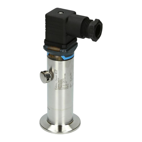
Endress+Hauser Cerabar T PMP131 User manual