promesstec UMU 100-A-B User manual

promesstec GmbH I Niedersachsenstraße 4 I D- 48465 Schüttorf I Tel.:+49 (0)5923/ 90 229 0 I Fax:+49 (0)5923/ 90 229 29
E-Mail: office@promesstec.com I Internet: www.promesstec.com
User manual:
UMU 100-A-B from page 01
UMU 100-B-B from page 34
User manual
Universal measuring transducer UMU 100-A-B
version 2.1.1

2
promesstec GmbH I Niedersachsenstraße 4 I D- 48465 Schüttorf I Tel.:+49 (0)5923/ 90 229 0 I Fax:+49 (0)5923/ 90 229 29
E-Mail: office@promesstec.com I Internet: www.promesstec.com
Content
1. General................................................................................................................ 5
1.1 For information .............................................................................................. 5
1.2 Signs and abbreviations................................................................................ 5
2. transport, packaging and storage........................................................................ 7
2.1 transport........................................................................................................ 7
2.2 packaging...................................................................................................... 7
2.3 storage .......................................................................................................... 7
3. Safety rules ......................................................................................................... 8
3.1 Intended use of the product........................................................................... 8
3.2 Personnel qualification .................................................................................. 9
3.3 Special hazards............................................................................................. 9
4. Commissioning and operation........................................................................... 10
4.1 Before mounting.......................................................................................... 10
4.2 Mounting / Installation / configuration.......................................................... 10
5. Decomposition of the system UMU 100-A-B.................................................... 11
6. Universal-measuring transducer UMU 100-A-B ................................................ 12
7. Applications....................................................................................................... 13
8. Front display / programming front UMU-FD....................................................... 14
9. Mounting / demounting the UMU-FD................................................................. 15
10. Electrical specifications................................................................................... 16
11. Visualisaton in the UMU-FD............................................................................ 20
12.Connections.................................................................................................... 22
13. Block diagram................................................................................................. 23
14. Configuration / operating the function keys..................................................... 24
14.1 Documentation for routing diagram.......................................................... 24
14.2 Further explanations................................................................................. 24
14.3 Signal- and Sensor error indication without display front.......................... 24
14.4 Advanced functions.................................................................................. 25
15. routing diagram............................................................................................... 27
15.1 Flussdiagramm, erweiterte Einstellungen (ADV.SET).............................. 30
16. Help text overview .......................................................................................... 31
17. Maintenance, Dismounting, Return, Liability, Cleaning and Disposal............. 32
17.1 Maintenance, Dismounting....................................................................... 32
17.2 Return ...................................................................................................... 32

3
promesstec GmbH I Niedersachsenstraße 4 I D- 48465 Schüttorf I Tel.:+49 (0)5923/ 90 229 0 I Fax:+49 (0)5923/ 90 229 29
E-Mail: office@promesstec.com I Internet: www.promesstec.com
17.3 Liability..................................................................................................... 32
17.4 Cleaning................................................................................................... 32
17.5 Disposal ................................................................................................... 32
18. Installation....................................................................................................... 33
19. order code....................................................................................................... 34
1. General.............................................................................................................. 39
1.1 For information ............................................................................................ 39
1.2 Signs and abbreviations.............................................................................. 39
2. Transport, packaging and storage..................................................................... 41
2.1 Transport..................................................................................................... 41
2.2 packaging.................................................................................................... 41
2.3 storage ........................................................................................................ 41
3. safety instructions.............................................................................................. 42
3.1 Intended product use................................................................................... 42
3.2 Personal qualification .................................................................................. 43
3.3 Special hazards........................................................................................... 43
4. Commissioning and operation.......................................................................... 44
4.1 Before mounting.......................................................................................... 44
4.2 Mouning / Installation / configuration........................................................... 44
5. How to demount the UMU 100-B-B................................................................... 45
6. Universal-transducer UMU 100-B-B.................................................................. 46
7. Applications....................................................................................................... 47
8. Front display / Programming front UMU-FD...................................................... 48
9. Mounting / demounting the UMU-FD................................................................. 49
10. Electrical specifications................................................................................... 50
11. Visualisation in the UMU-FD........................................................................... 55
12. Connections.................................................................................................... 57
13. Block diagram................................................................................................. 58
14. Configuration / operating the function keys..................................................... 59
14.1 Documentation for routing diagram.......................................................... 59
14.2 Further explanations................................................................................. 59
14.3 Signal- and sensor error info via display front UMU-FD........................... 60
14.4 Signal- and Sensor error indication without display front.......................... 60
14.5 Relay functions......................................................................................... 60
14.6 Latch ........................................................................................................ 61
14.7 Manuel deactivation of the latch function ................................................. 61

4
promesstec GmbH I Niedersachsenstraße 4 I D- 48465 Schüttorf I Tel.:+49 (0)5923/ 90 229 0 I Fax:+49 (0)5923/ 90 229 29
E-Mail: office@promesstec.com I Internet: www.promesstec.com
14.8 Advanced function.................................................................................... 62
15. routing diagram............................................................................................... 65
15.1 Routing diagram, advanced settings (ADV.SET) ..................................... 68
15.2 Routing diagram, manual deactivation of the latch function..................... 69
16. Help text overview .......................................................................................... 70
17. Grapic depiction.............................................................................................. 72
17.1 Grapic depiction of latch function setpoint................................................ 72
17.2 Graphic depiction of latch function window .............................................. 73
17.3 Graphic depiction of rely action setpoint................................................... 74
17.4 Graphische Abbildung der Relaisfunktion Fenster ................................... 74
18. Maintenance, Dismounting, Return, Liaility, Cleaning and Disposal............... 75
18.1 Maintenance, Dismounting....................................................................... 75
18.2 Return ...................................................................................................... 75
18.3 Liability..................................................................................................... 75
18.4 Cleaning................................................................................................... 75
18.5 Disposal ................................................................................................... 76
19. Installation....................................................................................................... 76
20. order code....................................................................................................... 77
5
promesstec GmbH I Niedersachsenstraße 4 I D- 48465 Schüttorf I Tel.:+49 (0)5923/ 90 229 0 I Fax:+49 (0)5923/ 90 229 29
E-Mail: office@promesstec.com I Internet: www.promesstec.com
1. General
1.1 For information
-These operating manual provides important information on handling the
measuring element. A prerequisite for safe working is compliance with all
specified safety notes and instructions for action.
-The qualified personnel must have read and understood these operating manual
before mounting and starting up the sensor.
-These operating manual is a component part of the product. Therefore, keep
them in a place that is accessible to all users at all times, close to the place of
use.
-The local regulations and safety rules applicable to the area of application of the
sensor must be observed.
-If the serial number on the type label is no longer readable (e.g.due to
mechnical damage), tracebility is no longer ensured.
-The sensors described in the user manual are developed and manufactured
according to the newest findings. All components are subject strict quality and
environmental criteria during production.
-The manufacturer shall not be liable if damage is caused by improper use,
non-observance of these operating instructions, use of insufficiently qualified
personnel and unauthorized modifications to the sensor.
1.2 Signs and abbreviations
Warning!
Non-observance can lead to injuries to persons and /or destruction of
the device. There may be danger to life.
Attention!
Non-observance can lead to incorrect operation of the device or
damage to property.
Information!
Non-observance can influence the operation of the device or cause
undesired device reactions.
Danger!
If the safety instructions are not observed, there is a risk of serious or
fatal injury from electric current
UMU 100-A-B

6
promesstec GmbH I Niedersachsenstraße 4 I D- 48465 Schüttorf I Tel.:+49 (0)5923/ 90 229 0 I Fax:+49 (0)5923/ 90 229 29
E-Mail: office@promesstec.com I Internet: www.promesstec.com
Warning!
A dangerous situation may possibly occur, which can lead to burns
due to hot surfaces or liquids if they are not avoided.
Warning!
This device is designed for connection to hazardous electric
voltages. Ignoring this warning can result in severe personal injury or
mechanical damage. To avoid the risk of electric shock and fire, the
safety instructions of this manual must be observed and the
guidelines followed. The specifications must not be exceeded, and
the device must only be applied as described in the following. Prior to
the commissioning of the device, this manual must be examined
carefully. Only qualified personnel (technicans) should install this
device. If the equipment is used in manner not specified by the
manufacturer, the protection provieded by the equipment may be
impaired.
Warning!
No dangerous voltage may be connected to the device before its per-
manent installation has been completed, and the following measures
should only be carried out when the device is in a de-energized state
and under ESD-safe conditions:
Installation, assembly and disassembly of pipelines.
Troubleshooting the device.
Warning!
The front panel of the device must not be opened, as this may da-
mage the contacts for contacting the UMU-FD front display.
The device does not contain any internal DIP switches or program-
ming jumpers.
The UMU 100 must be mounted on a DIN rail according to DIN 60715.
7
promesstec GmbH I Niedersachsenstraße 4 I D- 48465 Schüttorf I Tel.:+49 (0)5923/ 90 229 0 I Fax:+49 (0)5923/ 90 229 29
E-Mail: office@promesstec.com I Internet: www.promesstec.com
Triangle with exclamation mark: Warning / Regulation. Operations
that can lead to life-threatening situations. The manual must be read
carefully before installing and commissioning the device in order to avoid
serious injuries or mechanical destruction.
The CE-Mark is the visible sign that the device complies with the regula-
tions.
The double isulation symbol is the symbol that the device meets
special requirements for insulation.
2. transport, packaging and storage
2.1 transport
Inspect the device for a damage that may have occurred during transport. Report
obvious damage immediately.
2.2 packaging
Do not remove the packaging until immediately before assembly. Keep the packa-
ging, because it provides optimal protection during transport (e. g. changeable
installation location, return).
2.3 storage
Avoid the following influences during longer storage:
-Direct sunlight or close to hot objects
-Mechanical vibration, mechanical shock (hard set up)
-Soot, steam, dust and corrosive gases
If possible, store the device in the original packaging or appropriate packaging.

8
promesstec GmbH I Niedersachsenstraße 4 I D- 48465 Schüttorf I Tel.:+49 (0)5923/ 90 229 0 I Fax:+49 (0)5923/ 90 229 29
E-Mail: office@promesstec.com I Internet: www.promesstec.com
3. Safety rules
Further important safety instructions can be found in the individual
chapters.
Definitions:
Hazardous voltages have been defined as the range: 75...1500 Volt DC and
50...1000 Volt AC.
Technicians are qualified persons educated or trained to mount, operate, and also
trouble-shoot technically correct and in accordance with safety regulations.
Operators, are persons who set or operate the pushbuttons or potentiometers of the
product during normal operation and who have been familiarized with the contents of
this manual.
Receipt and unpacking:
Unpack the device without damaging it and check the device type
corresponds to the one ordered. The packaging should always follow with the
device until this has been permanently mounted.
3.1 Intended use of the product
Environment:
Avoid direct sunlight, strong dust or heat, mechanical shocks and impacts; do not
expose the device to rain or strong humidity. If necessary, heating is excess of the
stated limits for ambient temperatures should be avoided by way of ventilation. The
device must be installed in pollution degree 2 or better.
9
promesstec GmbH I Niedersachsenstraße 4 I D- 48465 Schüttorf I Tel.:+49 (0)5923/ 90 229 0 I Fax:+49 (0)5923/ 90 229 29
E-Mail: office@promesstec.com I Internet: www.promesstec.com
3.2 Personnel qualification
Risk of injury due to insufficient qualification Improper handling can
lead to considerable personal injury and property damage.
The activities described in these operating instructions may only be
performed by qualified personnel with the following qualifications.
Keep unqualified personnel away from the hazardous areas.
For mounting and commissioning of the sensor, these persons must be familiar with
the applicable country-specific directives and standards, and have the appropriate
qualification. You must have knowledge of measurement and control technology, be
familiar with electrical circuits and be able to carry out the work described and recog-
nize possible hazards independently. Depending on the operating conditions, other
knowledge may also be required, e.g. about aggressive media.
3.3 Special hazards
Observe the country-specific regulations (e.g. standards) and, in the
case of special applications, observe the applicable standards and
directives (e.g. for hazardous media such as Acetylene, flammable
or toxic substances as well as refrigeration plants and compres-
sors).
If the relevant regulations are not observed, serious personal
injury and damage to property may result!
Electrostatic discharge (ESD) protection is required. Proper use of
grounded work surfaces and personal wrist straps is required when
working with open circuits (printed circuit boards) to prevent damage
to sensitive electronic components from electrostatic discharge.
There is danger to life from electric current. There is a immediate risk
of death if live parts are touched. Installation and mounting of
electrical equipment may only be carried out by qualified electricians.
When operating with a defective power supply unit (e.g. short-circuit
from mains voltage to output voltage), life-threatening voltages can
result at the device.
Residual media in devices that have been removed can be
hazardous to persons, the environmet and equipment. Sufficient
precautions must be taken. This device must not be used in safety or
emergency stop devices. Incorrect applications of the device can
lead to injuries. In case of a fault, aggressive media at extreme
temperatures and under high pressure or vacuum may be present at
the device.

10
promesstec GmbH I Niedersachsenstraße 4 I D- 48465 Schüttorf I Tel.:+49 (0)5923/ 90 229 0 I Fax:+49 (0)5923/ 90 229 29
E-Mail: office@promesstec.com I Internet: www.promesstec.com
4. Commissioning and operation
4.1 Before mounting
Check whether a completely assembled measuring transducer has
been supplied. Inspect the device for any transport damage that
may have occurred. If such damage ispresent, notify the carrier and
supplier immediately. Keep the packaging, as it provides optimum
protection during tranport. Make sure that the housing and the
connection contacts are not damaged.
4.2 Mounting / Installation / configuration
•Due to the extremely low power consumption, the units can be mounted side by
side without an air gap between them even at an ambient temperature of 60°C.
•Configuration, monitoring, 2-point process calibration and more are performed
with either the UMU-FD detachable displays.
•All programming can be password protected.
Calibration and adjustment
During calibration and adjustment, the measurement and connection of external vol-
tages must be carried out in accordance with this manual, and the technician must
use tools and instruments that are safe for this purpose.
Normal operation
The operating personnel may only set or operate the device if these are permanently
installed in control panels or similar in a justifiable manner so that the operation does
not involve any danger to life or material. I.e., there must be no danger from contact
and the device must be placed so that it can be easily operated.

11
promesstec GmbH I Niedersachsenstraße 4 I D- 48465 Schüttorf I Tel.:+49 (0)5923/ 90 229 0 I Fax:+49 (0)5923/ 90 229 29
E-Mail: office@promesstec.com I Internet: www.promesstec.com
5. Decomposition of the system UMU 100-A-B
First, disconnect dangerous voltage from the terminals.
The device is released from the DIN rail by loosening the lower catch.
When the front LED is red / display shows AO.ER
The device has been developed with a high level of safety. Therefore, a continuous
measurement of the output current takes place at the 4...20 mA output signal. When
the current is 0 mA, the device switches to error mode and the LED indicator lights
red. This function is not a standard option, but must be actively selected in the menu.
The error mode can only be reset by switching the power supply of the device off and
on again.

12
promesstec GmbH I Niedersachsenstraße 4 I D- 48465 Schüttorf I Tel.:+49 (0)5923/ 90 229 0 I Fax:+49 (0)5923/ 90 229 29
E-Mail: office@promesstec.com I Internet: www.promesstec.com
6. Universal-measuring transducer UMU 100-A-B
• input for WTH, TE, Ohm, potentiometer, mA and V
• 2-wire supply > 16 V
• FM approval for installation in Div. 2
• Outputs for current and voltage
• Universal supply with AC or DC
Application
•Electronic, linear temperature measurement with resistance sensor or
thermocouple sensor.
•Conversion of linear resistance change into a standard analog current / voltage
signal, e.g. from solenoid valves, butterfly valves or linear movements with
connected potentiometers.
•Power supply and signal isolator for 2-wire measuring transducer.
•Process control with standard analog output.
•Galvanic isolation of analog signals and measurement of signals that are not
grounded.
•Suitable for use in systems up to Performance Level (PL) "d" according to ISO -
13849
Technical characteristics
•When the UMU 100 is used in combination with the programming front, all opera-
tional parameters of the corresponding application can be adjusted. The UMU
100 is equipped with electronic hardware switches and it is not necessary to
open the device to set DIP switches.
•A green / red LED in the front of the device indicates normal operation and
malfunctions.
•Constant checking of important memory data for security reasons.
•2,3 kVAC galvanic isolation of the 3 ports.

13
promesstec GmbH I Niedersachsenstraße 4 I D- 48465 Schüttorf I Tel.:+49 (0)5923/ 90 229 0 I Fax:+49 (0)5923/ 90 229 29
E-Mail: office@promesstec.com I Internet: www.promesstec.com
7. Applications
Input signals:
Output signals:
Supply:

14
promesstec GmbH I Niedersachsenstraße 4 I D- 48465 Schüttorf I Tel.:+49 (0)5923/ 90 229 0 I Fax:+49 (0)5923/ 90 229 29
E-Mail: office@promesstec.com I Internet: www.promesstec.com
8. Front display / programming front UMU-FD
Functionality
The simple and easily understandable menu structure and the
explanatory help texts guide you effortlessly and automatically through
the configuration steps, thus making the product very easy to use.
Functions and configuration options are described in the section
„configuration / operating the function key“.
Application
•Communications interface for modification of operational parameters in UMU
100.
•Can be moved from one UMU 100 device to another and download the
configuration of the first unit to subsequent units.
•Fixed display for readout of process data and status.
Technical characteristics
•LCD display with 4 lines:
Line 1 (H = 5,57 mm) shows the Input signal.
Line 2 (H = 3,33 mm) shows the selected engineering unit.
Line 3 (H = 3,33 mm) shows analog output or TAG no.
Line 4 shows status for communication.
Programming access can be blocked by assigning a password. The password
is saved in the device. In order to ensure high degree of protection against
unauthorized modifications to the configuration.
15
promesstec GmbH I Niedersachsenstraße 4 I D- 48465 Schüttorf I Tel.:+49 (0)5923/ 90 229 0 I Fax:+49 (0)5923/ 90 229 29
E-Mail: office@promesstec.com I Internet: www.promesstec.com
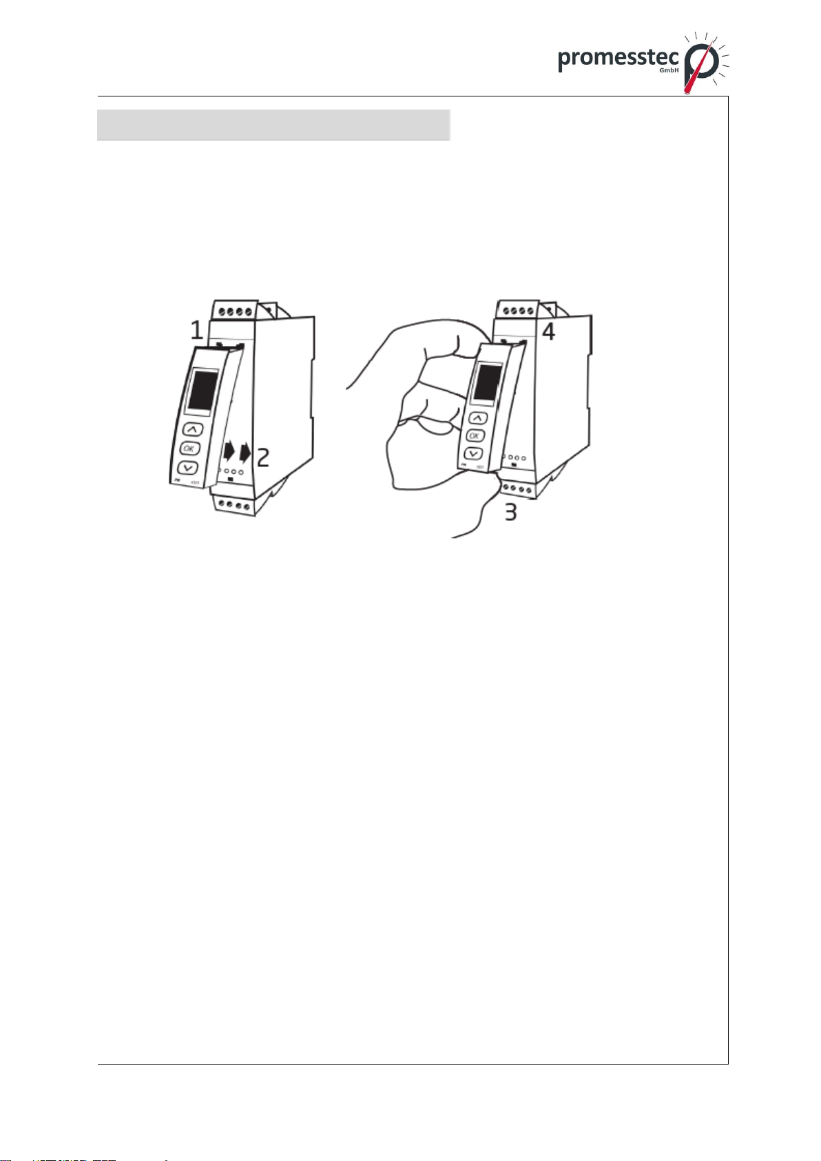
9. Mounting / demounting the UMU-FD
1: Insert the tabs of the UMU-FD into the holes at the top of the UMU 100.
2: Hinge the UMU-FD down until it snap into place.
Demounting of the UMU-FD
3/4: Press the release of the UMU-FD on the underside and carefully remove the
UMU-FD.

16
promesstec GmbH I Niedersachsenstraße 4 I D- 48465 Schüttorf I Tel.:+49 (0)5923/ 90 229 0 I Fax:+49 (0)5923/ 90 229 29
E-Mail: office@promesstec.com I Internet: www.promesstec.com
Order
UMU 100 = Universal-measuring transducer
UMU-FD = Display- / programming front
UMU-CJC = CJC-connector
10. Electrical specifications
Environmental conditions
Specification area. . . . . . . . . . . . . . . . . . . . . . . . . . . . . . -20°C to +60°C
Storage temperature. . . . . . . . . . . . . . . . . . . . . . . . . . . . -20°C to +85°C
Calibration temperature . . . . . . . . . . . . . . . . . . . . . . . . . .20...28°C
Relative humidity. . . . . . . . . . . . . . . . . . . . . . . . . . . . . . . < 95% RF (non cond.)
Protection degree . . . . . . . . . . . . . . . . . . . . . . . . . . . . . . IP20
Installation in pollution degree 2 & measurement / overvoltage category II
Mechnical specification
Dimensions (HxWxD) . . . . . . . . . . . . . . . . . . . . . . . . . . 109 x 23,5 x 104 mm
Dimensions (HxWxD) with UMU-FD. . . . . . . . . . . . . . . .109 x 23,5 x 116 / 131 mm
Weight, approx. . . . . . . . . . . . . . . . . . . . . . . . . . . . . . . . 155 g
Weight with UMU-FD (approx.). . . . . . . . . . . . . . . . . . . .170 g / 185 g
DIN rail type. . . . . . . . . . . . . . . . . . . . . . . . . . . . . . . . . . DIN EN 60715/35 mm
Cable cross section. . . . . . . . . . . . . . . . . . . . . . . . . . . . . 0,13...2,08 mm2 / AWG
26...14 stranded wire
Screw terminal torque. . . . . . . . . . . . . . . . . . . . . . . . . . . 0,5 Nm
Vibration. . . . . . . . . . . . . . . . . . . . . . . . . . . . . . . . . . . . . .IEC 60068-2-6
2...13,2 Hz . . . . . . . . . . . . . . . . . . . . . . . . . . . . . . . . . . . ±1 mm
13,2...100 Hz. . . . . . . . . . . . . . . . . . . . . . . . . . . . . . . . . . ±0,7 g
Common electrical specifications
Supply voltage, universal . . . . . . . . . . . . . . . . . . . . . . . . 21,6...253 VAC, 50...60 Hz
or 19,2...300 VDC
Fuse . . . . . . . . . . . . . . . . . . . . . . . . . . . . . . . . . . . . . . . . 400 mA SB / 250 VAC
Max. required power. . . . . . . . . . . . . . . . . . . . . . . . . . . . ≤ 2,0 W
Max. power dissipation. . . . . . . . . . . . . . . . . . . . . . . . . . ≤ 2,0 W
Isolation voltage, test. . . . . . . . . . . . . . . . . . . . . . . . . . . .2,3 kVAC
Isolation voltage, working . . . . . . . . . . . . . . . . . . . . . . . .250 VAC (reinforced) / 500
VAC (basic)
Programming . . . . . . . . . . . . . . . . . . . . . . . . . . . . . . . . . UMU-FD
Signal dynamics, input / output . . . . . . . . . . . . . . . . . . . .24 Bit / 16 Bit
Signal- / noise ratio. . . . . . . . . . . . . . . . . . . . . . . . . . . . . .> 60 dB (0...100 kHz)
Responsing time (0...90%, 100...10%):
Temperature Input. . . . . . . . . . . . . . . . . . . . . . . . . . . . . . ≤ 1 s
mA- / V-input . . . . . . . . . . . . . . . . . . . . . . . . . . . . . . . . . . ≤ 400 ms
Auxiliary supplies
2-wire-supply (terminal 44...43) . . . . . . . . . . . . . . . . . . . .25...16 VDC / 0...20 mA

17
promesstec GmbH I Niedersachsenstraße 4 I D- 48465 Schüttorf I Tel.:+49 (0)5923/ 90 229 0 I Fax:+49 (0)5923/ 90 229 29
E-Mail: office@promesstec.com I Internet: www.promesstec.com
Accuracy, the greater of general and basic values:
General values
Input type
Absolute accuracy
Temperature coefficient
All
≤ ±0,1% of span
≤ ±0,01% of span / °C
Basic values
Type
Basic accuracy
Temperature coefficient
mA
≤ ± 4 µA
≤ ± 0,4 µA / °C
Volt
≤ ± 20 µV
≤ ± 2 µV / °C
Pt100
≤ ± 0,2 °C
≤ ± 0,01 °C / °C
Linear resistance
≤ ± 0,1 Ω
≤ ± 0,01 Ω / °C
Potentiometer
≤ ± 0,1 Ω
≤ ± 0,01 Ω / °C
TC type:
E, J, K, L, N, T, U
≤ ± 1 °C
≤ ± 0,05 °C / °C
TC type: R, S, W3,
W5, LR
≤ ± 2 °C
≤ ± 0,2 °C / °C
TC type: B
85...200°C
≤ ± 4 °C
≤ ± 0,4 °C / °C
TC type: B
200...1820°C
≤ ± 2 °C
≤ ± 0,2 °C / °C
EMC –immunity influence . . . . . . . . . . . . . . . . . . . . . . . .<±0,5% of span
Extended EMC immunity:
NAMUR NE 21, A criterion, burst . . . . . . . . . . . . . . . . . . .<±1% of span
Input specifications
RTD-, linear resistance- and potentiometer input
Input for RTD types:
Pt10, Pt20, Pt50, Pt100, Pt200, PT250, Pt300, Pt400, Pt500, Pt1000
Ni50, Ni100, Ni120, Ni1000, Cu10, Cu20, Cu50, Cu100
Input type
Min. value
Max. value
Standard
Pt10…Pt1000
-200°C
+850°C
IEC 60751
Ni50…Ni1000
-60°C
+250°C
DIN 43760
Cu10…Cu100
-200°C
+260°C
= 0.00427
Lin.R
0 Ω
10000 Ω
-
Potentiometer
10 Ω
100 kΩ
-

18
promesstec GmbH I Niedersachsenstraße 4 I D- 48465 Schüttorf I Tel.:+49 (0)5923/ 90 229 0 I Fax:+49 (0)5923/ 90 229 29
E-Mail: office@promesstec.com I Internet: www.promesstec.com
Cable resistance per wire (max.), RTD. . . . . . . . . . . . . . . . . . .50 Ω
Sensor current, RTD . . . . . . . . . . . . . . . . . . . . . . . . . . . . . . . . Nom. 0,2 mA
Effect of sensor cable resistance (3- / 4-wire), RTD . . . . . . . .< 0,002 Ω / Ω
Sensor error detection, RTD . . . . . . . . . . . . . . . . . . . . . . . . . . Ja
Short circuit detection, RTD. . . . . . . . . . . . . . . . . . . . . . . . . . . < 15 Ω
TE-input
Type
Min. value
Max. value
Standard
B
0°C
+1820°C
IEC 60584-1
E
-100°C
+1000°C
IEC 60584-1
J
-100°C
+1200°C
IEC 60584-1
K
-180°C
+1372°C
IEC 60584-1
L
-200°C
+900°C
DIN 43710
N
-180°C
+1300°C
IEC 60584-1
R
-50°C
+1760°C
IEC 60584-1
S
-50°C
+1760°C
IEC 60584-1
T
-200°C
+400°C
IEC 60584-1
U
-200°C
+600°C
DIN 43710
W3
0°C
+2300°C
ASTM E988-90
W5
0°C
+2300°C
ASTM E988-90
LR
-200°C
+800°C
GOST 3044-84
Cold junction compensation (CJC):
Via external sensor in connector CJC. . . . . . . . . . . . . . . . 20...28°C ≤ ± 1°C
-20...20°C / 28...70°C ≤±2°C
Via internal CJC sensor . . . . . . . . . . . . . . . . . . . . . . . . . .±(2,0°C + 0,4°C * Δt)
Δt = internal temperature - ambient temperature
Sensor error detection, all TE-Types . . . . . . . . . . . . . . . .Yes
Sensor error current:
When detecting. . . . . . . . . . . . . . . . . . . . . . . . . . . . . . . . .Nom. 2 μA
else. . . . . . . . . . . . . . . . . . . . . . . . . . . . . . . . . . . . . . . . . .0 μA
Current input
Measurement range. . . . . . . . . . . . . . . . . . . . . . . . . . . . .0...23 mA
Programmable measurement ranges. . . . . . . . . . . . . . . .0...20 and 4...20 mA
Input resistance. . . . . . . . . . . . . . . . . . . . . . . . . . . . . . . . Nom. 20 Ω + PTC 50 Ω
Sensor error detection:
Loop break 4...20 mA. . . . . . . . . . . . . . . . . . . . . . . . . . . Yes
Voltage input
Measurement range. . . . . . . . . . . . . . . . . . . . . . . . . . . . 0..12 VDC
Programmable measurement ranges. . . . . . . . . . . . . . . 0...1 / 0,2...1 / 0...5 / 1...5 /
0...10 and 2...10 VDC
Input resistance. . . . . . . . . . . . . . . . . . . . . . . . . . . . . . . . Nom. 10 MΩ

19
promesstec GmbH I Niedersachsenstraße 4 I D- 48465 Schüttorf I Tel.:+49 (0)5923/ 90 229 0 I Fax:+49 (0)5923/ 90 229 29
E-Mail: office@promesstec.com I Internet: www.promesstec.com
Output specifications
Current output
Signal range (span) . . . . . . . . . . . . . . . . . . . . . . . . . . . . .0...23 mA
Programmable signal ranges . . . . . . . . . . . . . . . . . . . . . 0...20 / 4...20 / 20...0
and 20...4 mA
Load (max.). . . . . . . . . . . . . . . . . . . . . . . . . . . . . . . . . . . ≤ 800 Ω
Load stability. . . . . . . . . . . . . . . . . . . . . . . . . . . . . . . . . . ≤ 0,01% of span / 100 Ω
Sensor error detection . . . . . . . . . . . . . . . . . . . . . . . . . . .0 / 3,5 / 23 mA / none
NAMUR NE 43 Up- / Downscale . . . . . . . . . . . . . . . . . . .23 mA / 3,5 mA
Output limitation:
4...20 and 20...4 mA signals . . . . . . . . . . . . . . . . . . . . . . 3,8...20,5 mA
0...20 and 20...0 mA signals . . . . . . . . . . . . . . . . . . . . . . 0...20,5 mA
Current limit . . . . . . . . . . . . . . . . . . . . . . . . . . . . . . . . . . ≤ 28 mA
Voltage output
Signal range . . . . . . . . . . . . . . . . . . . . . . . . . . . . . . . . . . 0...10 VDC
Programmable signal rages . . . . . . . . . . . . . . . . . . . . . . 0...1 / 0,2...1 / 0...10 / 0...5 /
1...5 / 2...10 / 1...0 / 1...0,2 / 5...0 / 5...1 / 10...0 and 10…2 V
Load (min.) . . . . . . . . . . . . . . . . . . . . . . . . . . . . . . . . . . . 500 kΩ
Of span. = of the currently selected measurement range

20
promesstec GmbH I Niedersachsenstraße 4 I D- 48465 Schüttorf I Tel.:+49 (0)5923/ 90 229 0 I Fax:+49 (0)5923/ 90 229 29
E-Mail: office@promesstec.com I Internet: www.promesstec.com
11. Visualisaton in the UMU-FD
Sensor error detection and input signal outside range
Sensor error check:
Device
Configuration
Sensor error detection:
UMU 100-A-B
OUT.ERR=NONE.
OFF
Else:
ON
Outside range readout (IN.LO, IN.HI):
If the valid of the A/D converter or the polynomial is exceeded
Input
Range
Readout
Limit
Volt
0…1 V / 0,2…1 V
IN.LO
< - 25 mV
IN.HI
> 1,2 V
0…10 V / 2…10 V
IN.LO
< - 25 mV
IN.HI
>12 V
CURR
0…20 mA / 4…20 mA
IN.LO
< - 1,05 mA
IN.HI
> 25.05 mA
LIN.R
0…800Ω
IN.LO
< 0 Ω
IN.HI
> 1075 Ω
0…10 kΩ
IN.LO
< 0 Ω
IN.HI
< 110 kΩ
POTM
-
IN.LO
< - 0,5 %
IN.HI
> 100,5 %
TEMP
TC / RTD
IN.LO
< temperature range -2°C
IN.HI
> temperature range +2°C
Display readout below min. / above max. (-1999, 9999):
Input
Range
Readout
Limit
All
All
-1999
Display readout <-1999
9999
Display readout > 9999
Sensor error detection limits
Sensor error detection (SE.BR, SE.SH):
Input
Range
Readout
Limit
CURR
Loop break (4…20 mA)
SE.BR
<= 3.6 mA; > = 21 mA
POTM
All, SE.BR on all 3-wire
SE.BR
> ca. 126 kΩ
LIN.R
0…800 Ω
SE.BR
> ca. 875 Ω
0…10 kΩ
SE.BR
> ca. 11 kΩ
TEMP
TC
SE.BR
> ca. 750 kΩ/ (1.25 V)
RTD, 2-, 3-, and 4-wire
No SE.SH for Cuxx, Pt10,
PT20 and Pt50
SE.BR
> Ca. 15 kΩ
SE.SH
< ca. 15 kΩ
UMU 100
This manual suits for next models
1
Table of contents
Other promesstec Transducer manuals


