Hewlett Packard Enterprise R/T2200 G5 User manual

HPE R/T2200 G5 UPS, R/T3000 G5 UPS,
and ERM
User Guide
Abstract
This document is for the person who installs, administers, and troubleshoots power products.
Hewlett Packard Enterprise assumes you are qualified in the servicing of high-voltage
equipment and trained in recognizing hazards in products with hazardous energy levels.
Part Number: 881628-001a
June 2018
Edition: 2

Page 2 881628-001 Edition 2
© Copyright 2018 Hewlett Packard Enterprise Development LP
The information contained herein is subject to change without notice. The only warranties for Hewlett Packard
Enterprise products and services are set forth in the express warranty statements accompanying such products and
services. Nothing herein should be construed as constituting an additional warranty. Hewlett Packard Enterprise shall
not be liable for technical or editorial errors or omissions contained herein.

881628-001 Edition 2 Page 3
ENGLISH
Special Symbols
The following are examples of symbols used on the UPS or accessories to alert you to important
information:
RISK OF ELECTRIC SHOCK - Observe the warning associated with the risk of electric shock symbol.
Important instructions that must always be followed.
Do not discard the UPS or the UPS batteries in the trash.
This product contains sealed lead acid batteries and must be disposed as stated in this manual.
For more information, contact your local recycling/reuse or hazardous waste center.
This symbol indicates that you should not discard waste electrical or electronic equipment (WEEE)
in the trash. For proper disposal, contact your local recycling/reuse or hazardous waste center.
IMPORTANT SAFETY INSTRUCTIONS
SAVE THESE INSTRUCTIONS. This manual contains important instructions
that should be followed during installation and maintenance of the UPS and batteries.
The 2U UPS models that are covered in this manual are intended for installation in an environment
within 0 to 40°C/32 to 104°F, free of conductive contaminant.
• For HPE R/T3000 HV NA/JP and HPE R/T3000 G5 INTL UPS models: FCC/EN55022
Class B IEC62040-2 C1.
• For HPE R/T2200 G5 NA/JP and HPE R/T3000 G5 LV NA/JP UPS models: FCC/EN55022
Class A, IEC62040-2 C2
Certification Standards
• UPS directives: UL 1778 (UL listed).
• Performance: IEC 62040-3: 2001.
• Radiated emission: FCC CFR 47 part 15 subpart B (Class A or Class B, depending on
model).
• Surges withstand ability: IEEE ANSI C62.41 Category A2 (UL Listed).
Regulatory Notices
For more information, see HPE EG regulatory notices at
www.hpe.com/support/Safety-Compliance-EnterpriseProducts.

Page 4 881628-001 Edition 2
Personal Safety
• The system has its own power source (the battery). Consequently, the power outlets
may be energized, even if the system is disconnected from the AC power source.
• Dangerous voltage levels are present within the system.The system should be opened
exclusivelybyqualiedservicepersonnel.
• The system must be properly grounded.
• The battery supplied with the system contains small amounts of toxic materials.
• There are no user serviceable parts inside the system, except for the replaceable
battery.
• To avoid accidents, observe the following directives:
- Servicing of batteries should be performed or supervised by personnel
knowledgeable about batteries and the required precautions.
- When replacing batteries, replace with the same type and number of batteries or
battery packs.
- Donotdisposeofbatteriesinare.Thebatteriesmayexplode.
- Batteries constitute a danger (electrical shock, burns).The short-circuit current may
be very high.
• Precautions must be taken for all handling:
• Wear rubber gloves and boots.
• Do not lay tools or metal parts on top of batteries.
• Disconnect charging source prior to connecting or disconnecting battery terminals.
• Determine if the battery is inadvertently grounded. If inadvertently grounded, remove
source from ground. Contact with any part of a grounded battery can result in electrical
shock. The likelihood of such shock can be reduced if such grounds are removed during
installation and maintenance (applicable to equipment and remote battery supplies not
having a grounded supply circuit).
Product Safety
• The UPS should only power IT equipment.
• Do not plug laser printers into the UPS output receptacles.The instantaneous current drawn by this
type of printer can overload the UPS.
• The UPS connection instructions and operation described in this manual must be followed in
order.
• A protection circuit breaker must be installed upstream and be easily accessible.
The system can be disconnected from the AC power source by opening this circuit breaker.
• Verify that the indications on the rating plate correspond to your AC powered system and to
the actual electrical consumption of all the equipment to be connected to the system.
• For pluggable equipment, the socket-outlet shall be installed near the equipment and shall
be easily accessible.
• Never install the system near liquids or in an excessively damp environment.
• Never let a foreign body penetrate inside the system.
• Never block the ventilation grates of the system.
• Never expose the system to direct sunlight or source of heat.
• If the system must be stored prior to installation, storage must be in a dry place.
• The storage temperature range is -15°C to +50°C (5°F to 122°F).
Special Precautions
• All handling operations require at least two people (unpacking, installation in rack system).
• Before and after the installation, if the UPS remains de-energized for a period of more than 6
months, the UPS must be energized for a period of 24 hours, at least once every 6 months (for
a normal storage temperature less than 25°C/77°F).This charges the battery and avoids possible
irreversible damage.
• During the replacement of the battery module, use the same type and number of
element as the original Battery Module provided with the UPS to maintain an identical level of
performance and safety. For questions, contact your HPE representative.

881628-001 Edition 2 Page 5
ENGLISH
Contents
Table of Contents
1. Overview .......................................................................................................................6
1.1 Environmental protection................................................................................................6
1.2 Weights and dimensions .................................................................................................7
1.3 Rear panels.......................................................................................................................8
2. User Interface...............................................................................................................9
2.1 Control panel....................................................................................................................9
2.2 LCD window ................................................................................................................... 10
2.3 Display functions ........................................................................................................... 11
2.4 User settings .................................................................................................................. 11
3. Installation ..................................................................................................................14
3.1Unpackingandcontentsverication............................................................................14
3.2 Battery module connection...........................................................................................16
3.3Tower installation ...........................................................................................................17
3.4 Rack installation .............................................................................................................17
3.5 Communication ports....................................................................................................20
3.6 UPS connection .............................................................................................................21
3.7 Ground connection........................................................................................................22
3.8 ERM and UPS installation .............................................................................................23
4. Operation.....................................................................................................................25
4.1 Start-up and normal operation.....................................................................................25
4.2 Starting the UPS on battery ..........................................................................................25
4.3 UPS shutdown ...............................................................................................................25
4.4 Operation on battery power .........................................................................................25
4.5 Return of AC input power..............................................................................................26
4.6 UPS remote control functions ......................................................................................26
5. Maintenance...............................................................................................................27
5.1Troubleshooting .............................................................................................................27
5.2UpdatingtheUPSrmware..........................................................................................27
5.3 Battery module replacement ........................................................................................28
5.4 Spares.............................................................................................................................29
6. Technical Specifications..........................................................................................30
6.1 HPE R/T2200 G5 NA/JP UPS and HPE R/T3000 G5 LV NA/JP UPS............................30
6.2 HPE R/T3000 G5 HV NA/JP UPS and HPE R/T3000 G5 INTL UPS..............................31
6.3 Glossary..........................................................................................................................32
7. Support.........................................................................................................................33
7.1 Accessing Hewlett Packard Enterprise Support ...........................................................33
7.2 Accessing updates..........................................................................................................33
7.3 Customer self repair.......................................................................................................33
7.4 Remote support ..............................................................................................................34
7.5 Warranty information .....................................................................................................34
7.6 Regulatory information..................................................................................................34
8. BSMI RoHS..................................................................................................................35

Page 6 881628-001 Edition 2
1. Overview
Save these instructions.This document contains important safety instructions that should be followed
during installation, operation, and maintenance of the UPS and batteries.
1.1 Environmental protection
Products are developed according to an eco-design approach.
Substances
This product does not contain CFCs, HCFCs , or asbestos.
Packing
To improve waste treatment and facilitate recycling, separate the various packing components.
• The cardboard used is comprised of over 50% of recycled cardboard.
• Sacks and bags are made of polyethylene.
• Packingmaterialsarerecyclableandbeartheappropriateidenticationsymbol 01
PET
.
Materials Abbreviations Number in the symbols
Polyethylene terephthalat PET 01
High-density polyethylene HDPE 02
Polyvinyl chloride PVC 03
Low-density polyethylene LDPE 04
Polypropylene PP 05
Polystyrene PS 06
Follow all local regulations for the disposal of packing materials.
End of life
Hewlett Packard Enterprise processes products at the end of their service lives in compliance with local
regulations. Hewlett Packard Enterprise works with companies in charge of collecting and eliminating our
products at the end of their service lives.
Product
The product is made up of recyclable materials.
Dismantling and destruction must take place in compliance with all local regulations concerning waste.
At the end of its service life, the product must be transported to a processing center for electrical and
electronic waste.
Battery
The product contains lead-acid batteries that must be processed according to applicable local regulations
concerning batteries.
The battery can be removed to comply with regulations and correct disposal.

881628-001 Edition 2 Page 7
ENGLISH
1. Overview
1.2 Weights and dimensions
Tower installation Rack installation
Description Weights
(lb/kg)
Dimensions (in/mm)
D x W x H
HPE R/T2200 G5 NA/JP UPS 30.5 / 67.2 20.6 x 17.4 x 3.4 / 523 x 442 x 86
HPE R/T3000 G5 LV NA/JP UPS 39.9 / 88.0 25.4 x 17.4 x 3.4 / 645 x 442 x 86
HPE R/T3000 G5 HV NA/JP UPS 38 / 83.8 25.4 x 17.4 x 3.4 / 645 x 442 x 86
HPE R/T3000 G5 INTL UPS 38 / 83.8 25.4 x 17.4 x 3.4 / 645 x 442 x 86
HPE R/T2200 G4 ERM 32.2 / 71.0 20.0 x 17.4 x 3.4 / 508 x 442 x 86
HPE R/T3000 G4 ERM 45.2 / 99.7 25.5 x 17.4 x 3.4 / 648 x 442 x 86

Page 8 881628-001 Edition 2
1. Overview
1.3 Rear panels
HPE R/T2200 G5 NA/JP UPS
8a
8b
HPE R/T3000 G5 LV NA/JP UPS
8a
8b
11
HPE R/T3000 G5 HV NA/JP UPS and HPE R/T3000 G5
INTL UPS
8a 8b
NOTE: The R/T3000 and R/T2200 have 3 programmable output
loadsegments.ThesearedenedasGroup1,Group2,and
PrimaryGroup.Theloadsegments/groupscanbecongured
via software and the unit’s user interface. For advice on
configuration through software, see the HPEPP software or the
Hewlett Packard Enterprise networking device documentation.
To configure the UPS through the front panel, see "2.4 User
settings". Load Groups 1 and 2 can be programmed to switch
off/on independently. The Primary Load Group controls the
outlets indicated and initiates a unit shutdown.The Primary
Load Group is intended for the most critical loads.
HPE R/T2200 G4 ERM and HPE R/T3000 G4 ERM
(optional battery module) 12 Connectors for battery modules
(to the UPS or to the other battery
modules)
13 Connectors for automatic
recognition of battery modules
1USB communication port
2RS-232 communication port
3Connector for automatic recognition
of an additional battery module
4Slot for optional communication
card
5Connector for ROO (remote on/off)
or RPO (remote power off) control
6Connector for additional battery
module
730A outlet (L5-30R) for connection
of equipment (2U R/T3000 G5 LV
NA/JP UPS only)
8a Group 1: Two programmable outlets
for connection of equipment
8b Group 2: Two programmable outlets
for connection of equipment
9Primary Group: outlets for
connection of critical equipment
10 Attached 8-ft. input power cord for
AC power source
5-20P for 2200
L5-30P for 3000
11 LED indicating SWF (site wiring
fault) alarm (Although the LED
remains on the rear panel, this
feature is disabled for low voltage
models.)
12 Ground connection
1USB communication port
2RS-232 communication port
3Connector for automatic recognition
of an additional battery module
4Slot for optional communication
card
5Connector for ROO (remote on/off)
or RPO (remote power off) control
6Connector for additional battery
module
716A outlet for connection of
equipment (primary group)
8a Group 1: Two programmable outlets
for connection of equipment
8b Group 2: Two programmable outlets
for connection of equipment
9Primary Group: 4 outlets for
connection of critical equipment
10 Outlet for connection to AC power
source
11 Ground connection

881628-001 Edition 2 Page 9
ENGLISH
2. User Interface
2.1 Control panel
TheUPShasave-buttongraphicalcontrolpanel.
Power On
Indicator (green)
On battery
Indicator (yellow)
Alarm
Indicator (red)
Normal mode
100%
17min
1ERM
100%
2.7kW
3kVA
Eciency: ~98%
Escape Up Down Enter On/Off
button
The following table shows the indicator status and description:
Indicator Status Description
Green On The UPS is operating normally.
Yellow On The UPS is on Battery mode.
Red
On The UPS has an active alarm or fault. For more
information, see "5.1 Troubleshooting".
Page 10 881628-001 Edition 2
2. User Interface
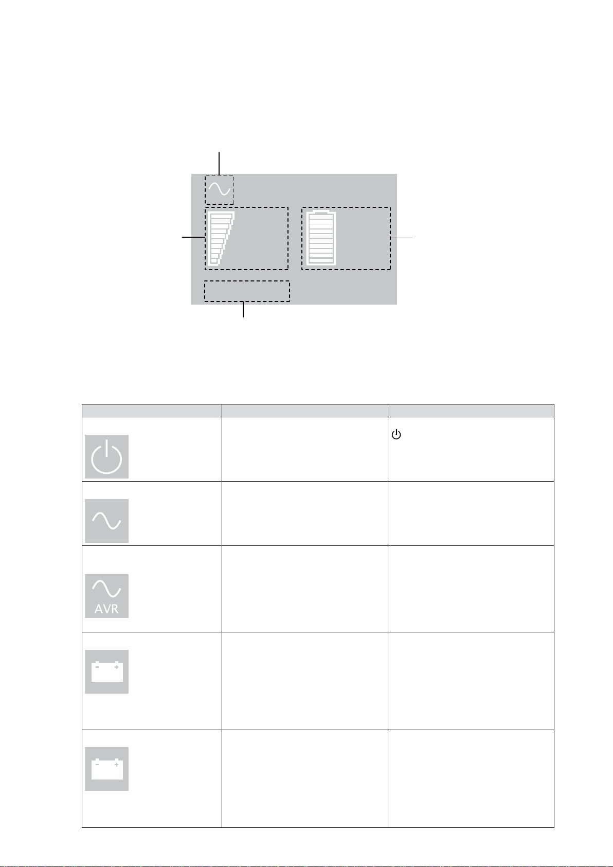
2.2 LCD window
The LCD window provides information about the UPS, load status, events, measurements, and settings. As
thedefault,orafterveminutesofinactivity,theLCDdisplaysthescreensaver.
The backlight LCD automatically dims after 10 minutes of inactivity. Press any button to restore the screen.
Operation Status
Load/equipment Status
Normal mode
100%
17min
1ERM
100%
2.7kW
3kVA
Eciency: ~98%
Battery Status
Efficiency and Load Group Information
The following table illustrates the Operation Status icons that you could see and describes the condition
associated with each icon.
NOTE: If other indicators appear, see "5.1Troubleshooting".
Operation status Possible cause Action
Standby mode The UPS is off, waiting for start-up
command from user.
Equipment is not powered until the
button is pressed.
Normal mode The UPS is operating normally. The UPS is powering and protecting
the equipment.
In Automatic Voltage
Regulation mode
No audio alarm.
The UPS is operating normally, but
the utility voltage is outside normal
mode thresholds.
The UPS is powering the
equipment through an AVR device.
The equipment is still normally
protected.
On Battery
Battery LED is on.
Audio alarm beeps every 10
seconds
A utility failure has occured and
the UPS is in Battery mode.
The UPS is powering the equipment
with the battery power.
Prepare your equipment for
shutdown.
End of backup time
Battery LED is flashing.
The audio alarm beeps every
three seconds
The UPS is in Battery mode and
the battery is running low.
This warning is approximate and
the actual time to shutdown may
vary significantly.
Depending on the UPS Load
and number of ERMs, the Battery
Low warning may occur before the
battery reaches 20% capacity.

881628-001 Edition 2 Page 11
ENGLISH
2.3 Display functions
Press the button to activate the menu options. Use the and buttons to scroll through the menu
structure. Press the button to select an option. Press the button to cancel or return to the previous
menu.
Menu map for Display Functions.
Main menu Submenu Display information or Menu function
Measurements — Load W VA / Load A pf / Output V Hz / Input V Hz /
Battery V min / Efficiency / Power usage
Control Load Segments Group 1: ON / OFF
Group 2: ON / OFF
These commands override user settings for load segments.
Start battery test Starts a manual battery test
Reset fault state Clears active fault (UPS restart required)
Restore factory settings Returns all settings to original values
Reset power usage Clears power usage measurements
Settings Local settings Sets general parameters
Input / output settings Sets input and output parameters
ON / OFF settings Sets on and off conditions
Battery settings Sets battery configuration
Fault log — Displays event log or alarms
Identification — UPS Type/Part Number/Serial Number/Firmware release/Com
card address
2.4 User settings
The following table displays the options that can be changed by the user.
Description Available settngs Default settings
Local settings
Language [English] [French] [German]
[Spanish] [Italian] [Portuguese]
[Russian]
Menus, status, notices and
alarms, UPS fault, event log data
and settings are in all supported
languages.
English
User selectable when UPS is
powered the first time.
LCD settings Allows LCD screen brightness and
contrast to be adapted to room
light conditions.
—
Audible alarm Mode [Enabled] [Disabled on battery]
[Always disabled]
Allows you to enable or disable the
audio alarm if an alarm occurs.
Enabled
Level [High] [Low]
Allows you to set the audio alarm
level if an alarm occurs.
Low
2. User Interface

Page 12 881628-001 Edition 2
2. User Interface
Description Available settngs Default settings
In/Out settings
Output voltage* [100V] [120V] [125V]
On INTL models: [200V] [208V] [220V]
[230V] [240V]
User selectable when UPS is
powered the first time.
*IMPORTANT: The output voltage of the UPS must be set to the same nominal voltage as the
facility input voltage for optimum UPS performance.
Input thresholds [Normal mode] [Extended mode]
Extended mode reduces lower
input voltage to 70V before UPS
transfers to battery.
This can be used if the load can
withstand low voltage supply.
Normal mode
Sensitivity [High] [Low]
High: For sensitive equipment. The
UPS transfers to battery when AC
utility conditions are poor.
Low: For equipment that can
withstand poor utility conditions.
The UPS does not transfer to
battery when AC utility conditions
are poor.
High
Load segments - Auto
start delay
[No Delay] [1 s] [2 s]…[65354 s]
The connected equipment is
powered after the specified delay.
Group 1: 3 s
Group 2: 6 s
In/Out settings
Load segments - Auto
shutdown delay
[Disable] [0 s] [1 s] [2 s]…[65354 s]
During a power outage,
authorizes UPS to turn off power to
equipment connected to Group 1
and/or Group 2 outlets.
This feature sheds non-critical
loads in order to conserve battery
power for critical loads connected
to the primary group.
Group 1: Disable
Group 2: Disable
Overload prealarm [10%] [15%] [20%] ... [100%] [105%]
Sets alarm for critical percentage of
load where alarm overload occurs.
[105%]

881628-001 Edition 2 Page 13
ENGLISH
2. User Interface
Description Available settngs Default settings
ON/OFF
settings
Cold start [Disable] [Enable]
Enables or disables the product to
start on battery.
The first cold start is always
disabled.
Enable
Forced reboot [Disable] [Enable]
If power returns during a shutdown
sequence:
If enabled, the shutdown sequence
will complete and there is a 10
second delay prior to restart.
If disabled, shutdown sequence
does not complete and restart
occurs immediately.
Enable
Auto restart [Disable] [Enable]
Enables or disables the UPS to
restart automatically when power
returns after a complete battery
discharge.
Enable
Energy saving [Disable] [Enable]
If enabled, the UPS will shutdown
after five minutes if no load is
detected on the output.
Disable
Sleep mode [Disable] [Enable]
If enabled, LCD and communication
stays on 1h and 30 min after UPS
turns off.
If disabled, LCD and
communication will turn off
immediately after the UPS turns
off.
Disable
Remote command [Disable] [Enable]
If enabled, shutdown or restart
commands from software are
allowed.
If disabled, shutdown or restart
commands from software are not
allowed.
Enable
RPO delay [0 s] [1 s ] [2 s]...[180 s]
Delays RPO command for the
specified number of seconds.
[0 s]
Battery
settings
Automatic battery test [No test] [Every day] [Every week]
[Every month]
Available only if Battery Charge
mode is set to constant charge.
Every week
(in constant charge)
otherwise following EBM
Low battery
warning
[1%] [2%] ... [100%]
The alarm occurs when the value
set
for the low battery capacity
warning is reached.
20%
Restart battery level [1%] [2%] ... [100%]
If set, automatic restart occurs only
when the percentage of battery
charge you specify is reached.
0%
Battery charge mode [EBM cycling] [Constant charge] EBM cycling
Deep discharge
protection
[Yes] [No]
If set to Yes, the UPS automatically
prevents the battery from deep
discharge by adapting the end of
the back-up time
voltage threshold.
Yes
Page 14 881628-001 Edition 2
Packing materials must be disposed of in compliance with all local regulations concerning waste.
Recycling symbols are printed on the packing materials to facilitate sorting.
3. Installation
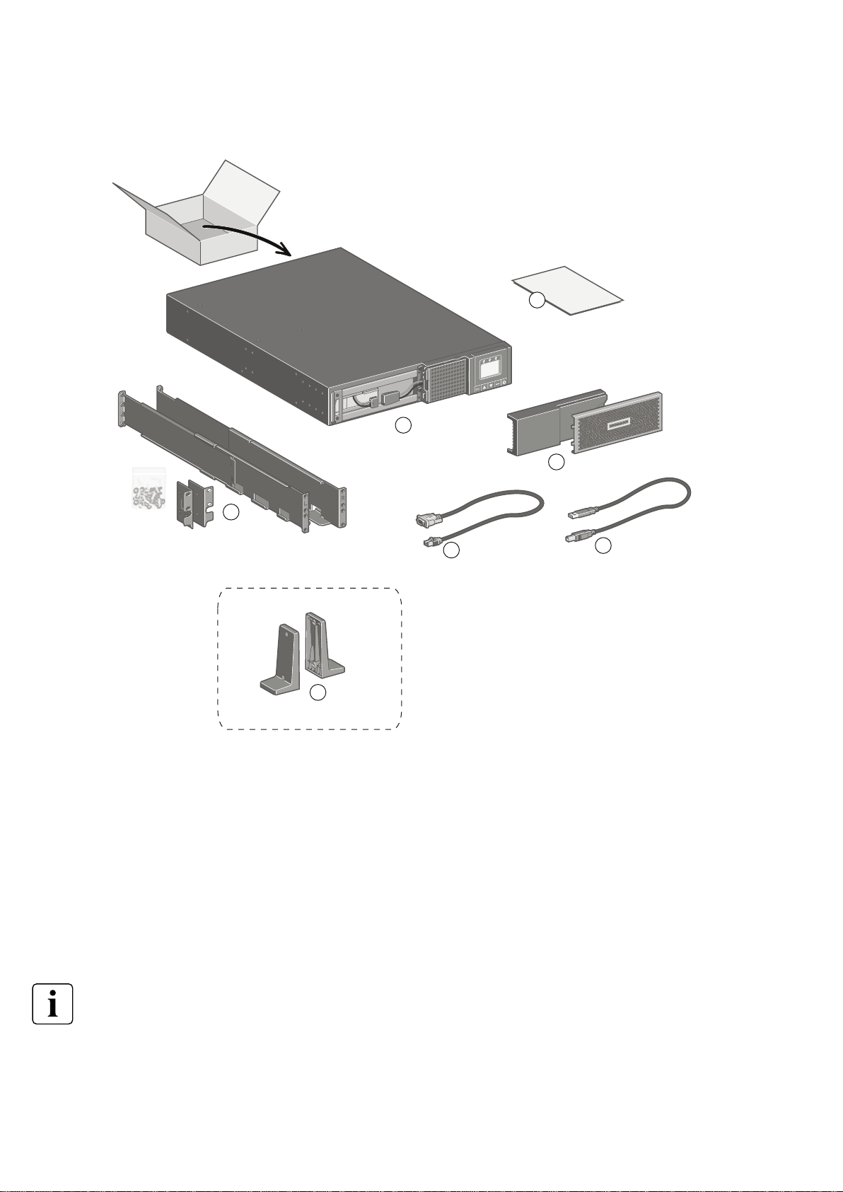
3.1 Unpacking and contents verification
HPE R/T2200 G5 NA/JP UPS and HPE R/T3000 G5 LV NA/JPN UPS
1
2
34
5
6
7
(1) HPE R/T2200 G5 NA/JP and HPE R/T3000 G5 LV
NA/JPN
(2) Bezel parts
(3) RS-232 communication cable
(4) USB communication cable
(5) Documentation
(6) Mounting brackets, rails, and hardware
(7) Tower stands

881628-001 Edition 2 Page 15
ENGLISH
HPE R/T3000 G5 HV NA/JPN UPS and HPE R/T3000 G5 INTL UPS
3. Installation
8
9
10
11
12
13
14
15
16
(8) HPE R/T3000 G5 HV NA/JPN and HPE R/T3000 G5
INTL
(9) Connection cable to AC power source
(L6-20P for NA/JP model. Country-specific cord for
INTL model)
(10) Two connection cables for the protected
equipment
(11) RS-232 communication cable
(12) USB communication cable
(13)Two cable locking systems
(14) Documentation
(15) Mounting brackets, rails, and hardware
(16) Tower stands
Packing materials must be disposed of in compliance with all local regulations concerning waste.
Recycling symbols are printed on the packing materials to facilitate sorting.

Page 16 881628-001 Edition 2
3. Installation
3.2 Battery module connection
CAUTION: This operation must be performed when the UPS is switched off and unplugged from the AC
source.
Do not disconnect the connector while the unit is operating from the AC source or in reserve mode.
NOTE: Before starting the UPS, connect the internal battery. A small amount of arcing may occur when
connecting the batteries.This is normal and does not damage the UPS or present any safety concern.
Installing the new battery module
Perform the removal instructions in reverse order.
●To ensure safety and high performance, only use batteries supplied by HPE.
●Take care to firmly press together the two parts of the connector during remounting.
AConnect the battery module.
Never pull on the wires.
BSlide the left-hand side of the bezel
to the right. Ensure that the push
button locks.
CAttach the center panel.

881628-001 Edition 2 Page 17
ENGLISH
3. Installation
3.3 Tower installation
3.4 Rack installation
WARNING! To reduce the risk of personal injury or damage to the equipment, be sure that:
• Thelevelingfeetareextendedtotheoor.
• The full weight of the rack rests on the leveling feet.
• The stabilizing feet are attached to the rack if it is a single-rack installation.
• The racks are coupled together in multiple-rack installations.
• Only one component is extended at a time. A rack may become unstable if more than one
component is extended for any reason.
NOTE: If preparing the rails for integrated shipping, follow the same rack installation instructions.
NOTE: Mounting hardware for square and round-holed racks is included in the UPS kit.

Page 18 881628-001 Edition 2
3. Installation
Installing the mounting rails and the UPS
Follow steps 1 through 4 for installing the mounting rails and installing the UPS in the rack.

881628-001 Edition 2 Page 19
ENGLISH
3. Installation
Shipping the UPS in the rack
Before shipping the UPS in the rack, you will need discard the rail kit that shipped with the UPS. You must
purchase the shipping kit part number L4Q11A which will add a rear rail stabilizing bracket and install a
protective cover over the bezel.
WARNING! To reduce the risk of personal injury or damage to the equipment, shipping kit part number
L4Q11A is required prior to moving or shipping a rack with an installed UPS.
Install the rear stabilizing rail
Reinstall the UPS
Attach the protective cover
AInstall the rear stabilizing rail.
1. Using two wing nuts,
secure the rear rail
stabilizing bracket to screws
in the rail (see diagram for
position). Repeat on the
other rail.
2. Wait until the unit is
installed and the brackets
are adjusted before
tightening the nuts. (See the
diagram at the left for inner
and outer rail installation
views.)
BReinstall the UPS chassis in
the rack.
1. With one person on each
side, lift the chassis to rail
level and slide the chassis
on the mounting rails.
2. Attach the chassis to the
rack using the provided
screws.
CAfter the UPS chassis
is installed in the rack,
attach the protective cover
over the bezel using the
provided screws.
B
A
C

Page 20 881628-001 Edition 2
3. Installation
3.5 Communication ports
Connection of RS-232 or USB communication port (optional)
The RS-232 and USB communication ports cannot operate simultaneously.
16
17 34
33
or
or
1. Connect the RS-232( 16
or 33 ) or USB ( 17 or 34 )
communication cable to the
serial or USB port on
the computer equipment.
2. Connect the other end of
the communication cable
to the USB 1or RS-232 2
communication port on
the UPS.
The UPS can now communicate
with HPE power management
software.
Installation of optional NMC Network Card
The UPS does not have to be powered down before installing a communication card.
1. Remove the mounting screws
and remove the slot cover 4.
2. Insert the communication
card in the slot.
3. Secure the card cover with
the screws removed in Step 1.
When a signal is activated, the contact is closed between the common (pin 2) and the pin for the
corresponding signal.
Contact characteristics (optocoupler)
• Voltage: 48 Vdc max
• Current: 25 mA max
• Power: 1.2W
Characteristics of the optocoupler RS-232 communications port
• Pins 1, 3, 4, 5, 6, 10: not used
• Pin 2: common (user)
• Pin 7: low battery
• Pin 8: operation on battery
power
• Pin 9: UPS on, equipment
supplied
no: normally open contact
This manual suits for next models
3
Table of contents
Other Hewlett Packard Enterprise UPS manuals


