Tescom TEOS+ 300 Series User manual

TEOS+ 300 SERIES
10-15-20-30 kVA
3 Phase In - 3 Phase Out
USER MANUAL


Preface
Usage
The manual contains information on installing, using, operation and maintenance of
the Tower UPS. Please carefully read this manual prior to installation.
Users
Technical Support Engineer
Maintenance Engineer
Note
Our company is providing a full range of technical support and services. Customer
can contact our local office or customer service center for help.
The manual will update irregularly, due to the product upgrading or other reasons.
Unless otherwise agreed,the manual is only used as guide for users and any
statements or information contained in this manual make no warranty expressed or
implied.


1
Contents
1.Important Safety Precautions........................................................................................................... 1
General Information....................................................................................................................1
UPS Safety.................................................................................................................................. 1
Battery Safety..............................................................................................................................2
Description of Symbols...............................................................................................................3
2. Product Introduction........................................................................................................................4
2.1 Introduction........................................................................................................................... 4
2.2 System Configuration........................................................................................................... 4
2.3 Operation Mode.................................................................................................................... 4
2.3.1 Normal Mode............................................................................................................. 4
2.3.2 Battery Mode............................................................................................................. 5
2.3.3 Bypass Mode..............................................................................................................5
2.3.4 Maintenance Mode (Manual Bypass)........................................................................6
2.3.5 ECO Mode................................................................................................................. 6
2.3.6 Auto-restart Mode...................................................................................................... 7
2.3.7 Frequency Converter Mode....................................................................................... 7
2.3.8 Self Aging Mode........................................................................................................7
2.4 UPS Structure........................................................................................................................8
2.4.1 UPS Configuration.....................................................................................................8
2.4.2 UPS Outlook.............................................................................................................. 8
3. Installation Instruction...................................................................................................................11
3.1 Location...............................................................................................................................11
3.1.1 Installation Environment..........................................................................................11
3.1.2 Site Selection............................................................................................................11
3.1.3 Size and Weight....................................................................................................... 11
3.1.4 Installation Tools..................................................................................................... 12
3.2 Unloading and Unpacking.................................................................................................. 12
3.2.1 Moving and Unpacking of the Cabinet....................................................................12
3.3 Positioning...........................................................................................................................13
3.3.1 Positioning Cabinet..................................................................................................13
3.4 Battery................................................................................................................................. 14
3.5 Cable Entry..........................................................................................................................14
3.6 Power Cables.......................................................................................................................15
3.6.1 Specifications...........................................................................................................15
3.6.2 Specifications for Power Cables Terminal.............................................................. 16
3.6.3 Circuit Breaker.........................................................................................................16
3.6.4 Connecting Power Cables........................................................................................17
3.7 Control and Communication Cables...................................................................................18
3.7.1 Dry Contact Interface...............................................................................................18
3.7.2 Communication Interface........................................................................................ 19

2
4. LCD Panel..................................................................................................................................... 21
4.1 Introduction......................................................................................................................... 21
4.2 LCD panel for Cabinet........................................................................................................21
4.2.1 LED Indicator.......................................................................................................... 21
4.2.1 Alarm........................................................................................................................21
4.2.2 LCD Menu structure................................................................................................ 22
4.2.3 Home page............................................................................................................... 22
4.2.4 System......................................................................................................................23
4.2.5 Alarm........................................................................................................................28
4.2.6 Control..................................................................................................................... 29
4.2.7Settings......................................................................................................................30
4.3 Event List............................................................................................................................ 36
5. Operations..................................................................................................................................... 40
5.1 UPS Start-up........................................................................................................................40
5.1.1 Start from Normal Mode..........................................................................................40
5.1.2 Start from Battery.................................................................................................... 40
5.2 Procedure for Switching between Operation Modes..........................................................41
5.2.1 Switching the UPS into Battery Mode from Normal Mode....................................41
5.2.2 Switching the UPS into Bypass Mode from Normal Mode.................................... 41
5.2.3 Switching the UPS into Normal Mode from Bypass Mode.................................... 41
5.2.4 Switching the UPS into Maintenance Bypass Mode from Normal Mode.............. 41
5.2.5 Switching the UPS into Normal Mode from Maintenance Bypass Mode.............. 42
5.3 Battery Maintenance........................................................................................................... 43
5.4 EPO..................................................................................................................................... 43
5.5 Installation of Parallel Operation System........................................................................... 44
5.5.1 Parallel system diagram........................................................................................... 44
5.5.2 Parallel system setting............................................................................................. 45
6. Maintenance.................................................................................................................................. 47
6.1 Precautions.......................................................................................................................... 47
6.2 Instruction for Maintaining UPS.........................................................................................47
6.3 Instruction for Maintaining Battery string..........................................................................47
7. Product Specification.................................................................................................................... 49
7.1 Applicable Standards.......................................................................................................... 49
7.2 Environmental Characteristics............................................................................................ 49
7.3 Mechanical Characteristic...................................................................................................50
7.4 Electrical Characteristics.....................................................................................................50
Annex A Installation of internal battery.........................................................................................52

1
1.Important Safety Precautions
General Information
Please read the "safety precautions" carefully before installing and using this
product to ensure correct and safe installation and use. Please keep this manual
properly.
UPS must be installed, tested and maintained by an engineer authorized by the
manufacturer or its agent, otherwise it is possible to endanger personal safety and
cause equipment failure. The damage to UPS caused thereon is excluded from the
warranty.
Under no circumstances shall equipment structure or components be dismantled
or changed without the manufacturer's permission, otherwise the damage to UPS
caused thereby shall not be covered by the warranty.
Local regulations and laws shall be followed when using equipment. The safety
precautions in the manual only supplement the local safety regulations.
Due to product version upgrade or other reasons, the content of this document
will be updated from time to time. Unless otherwise agreed, this document is used
only as a guide, and all statements, information and recommendations in this
document do not constitute any warranty, express or implied.
UPS Safety
Before installing the equipment, wear insulating protective clothing, use
insulating appliances, and remove conductive objects such as jewelry and
watches to avoid electric shock or burns.
The operating environment has a certain impact on the service life and reliability
of UPS. The environmental requirements set in the manual must be followed
when using and storing the equipment.
Avoid using the equipment in direct sunlight, rain, or in environments with
electrified dust.
When placing UPS, maintain a safe distance around it to ensure ventilation.
During operation of the system, do not block the vent.
Do not allow liquids or other foreign objects to enter into the UPS cabinet or
cabinet.
Before using UPS, check whether the local distribution characteristics are
consistent with the information of the product nameplate.
As UPS is a large leakage current device, it is not recommended to install
breakers with leakage protection function.
Before connecting UPS, please further confirm whether the switch connecting the
power supply of the UPS mains input/bypass power supply and the mains power
are disconnected.
When it is required to move or rewire UPS, make sure to disconnect AC input
power supply, battery and other inputs, and UPS is fully powered down (more
than 5min) before carrying out the corresponding operation, otherwise there may
still be power in the port and inside of the equipment, and it is possible to cause a
risk of electric shock.
Before powering on, please confirm the correct grounding, and check wire

2
connection and battery polarity to ensure correct connection. In order to ensure
personal safety and the normal use of UPS, UPS shall be reliably grounded before
use.
UPS can be used for resistive and capacitive (such as computers), resistive and
micro inductive load, not for pure capacitive and inductive load (such as motors,
air conditioners and copiers) and half wave rectifier load.
When cleaning the machine, please wipe it with a dry object. Under no
circumstances shall water be used to clean electrical parts inside or outside the
cabinet.
After completion of maintenance operations, check immediately to ensure that no
tools or other items are left in the cabinet.
In case of fire, please use dry powder extinguisher correctly for extinguishment.
There is a danger of electric shock if liquid fire extinguishers are used.
Do not close the breaker before the UPS installation is completed. Do not power
on UPS without the permission of a qualified electrician.
Battery Safety
Battery installation and maintenance shall only be performed by personnel with
battery expertise.
There is danger of electric shock and short circuit current in the battery. In order
to avoid safety accidents, when installing or replacing the battery, please pay
attention to the following matters: do not wear jewelry and watches and other
conductive objects; use special insulation tools; use facial protection; wear
protective insulating clothing; do not turn the battery upside down or tilt it;
disconnect the input breaker of the battery.
The installation environment of the battery must be far away from the hot area,
and it is not allowed to use or keep the battery near the fire source. The battery or
battery strings cannot be processed by fire, otherwise it is possible cause personal
injury due to explosion.
Environmental factors impact battery life. Elevated ambient temperatures, poor
quality utility power, and frequent short duration discharges will shorten battery
life.
The batteries should be regularly replaced to ensure the normal operation of UPS
and sufficient backup time.
Do not use a battery that is not approved by the supplier, as it may adversely
affect the operation of the system. Use of a non supplier approved battery will
void the manufacturer warranty.
Check the screws of the connecting parts of the battery regularly to make sure
they are tight and not loose. If the screws become loose parts, they must be
tightened immediately.
Please do not short the positive and negative terminals of the battery, Otherwise it
is possible to cause electric shock or fire.
Do not touch the wiring terminal of the battery. The battery circuit is not isolated
from the input voltage circuit, and there will be a high voltage hazard between the
battery terminal and the ground.
Do not open or damage the battery, otherwise it is possible to cause short circuit
and battery leakage and the electrolyte in the battery may cause damage to the

3
skin and eyes. In case of exposure into the electrolyte, wash immediately with
plenty of water and go to the hospital for examination.
Description of Symbols
The following symbols used herein have the following meaning.
Symbols
Description
It is used to warn of emergency and dangerous situations which may
lead to death or serious bodily injury if not avoided.
It is used to warn of potential dangerous situations which will lead to a
certain degree of personal injury if not avoided.
It is used to transmit the safety warning information of equipment or
environmental, which may lead to equipment damage, data loss,
equipment performance degradation or other unpredictable results if not
avoided.
It is used for further detailed description of the things, highlighting
important/critical information, etc.
DANGER
WARNING
CAUTION
NOTICE
4
2. Product Introduction
2.1 Introduction
The UPS supplies stable and uninterrupted power for the important load. It can
eliminate the power supply surge, instantaneous high/low voltage, harmonic and
frequency offset pollution, to provide high quality electrical energy to costomers.
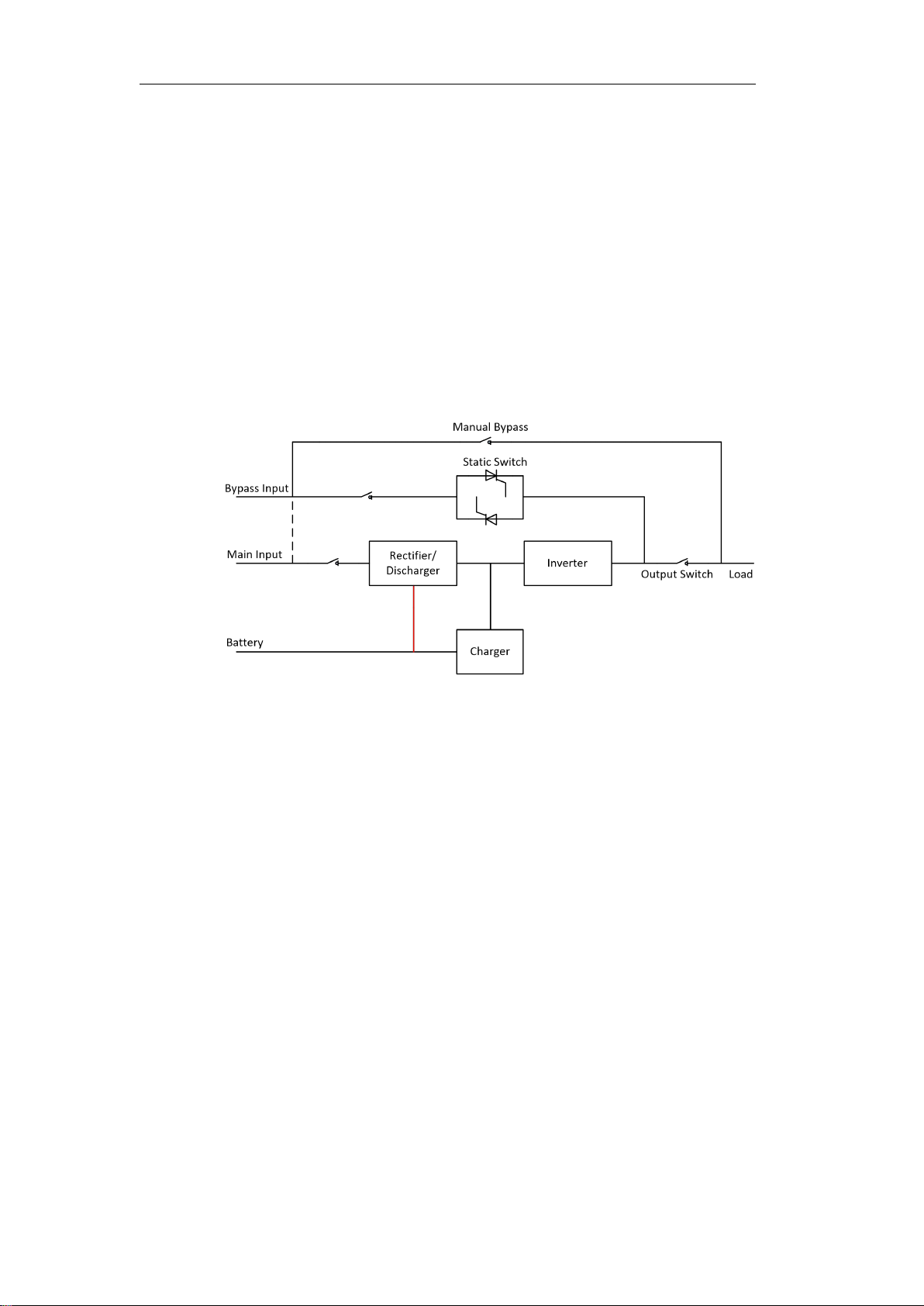
2.2 System Configuration
The Tower UPS is configured by the following part: Rectifier, Charger, Inverter,
Static Switch and Manual Bypass Switch. One or several battery strings should be
installed to provide backup energy once the utility fails. The UPS structure is shown
in Fig. 2-1.
Fig. 2-1 UPS Configuration
2.3 Operation Mode
The UPS is an on-line, double-conversion UPS that permits operation in the following
modes:
Normal mode
Battery mode
Bypass mode
Maintenance mode (manual bypass)
ECO mode
Auto-restart mode
Frequency Converter mode
Self Aging Mode
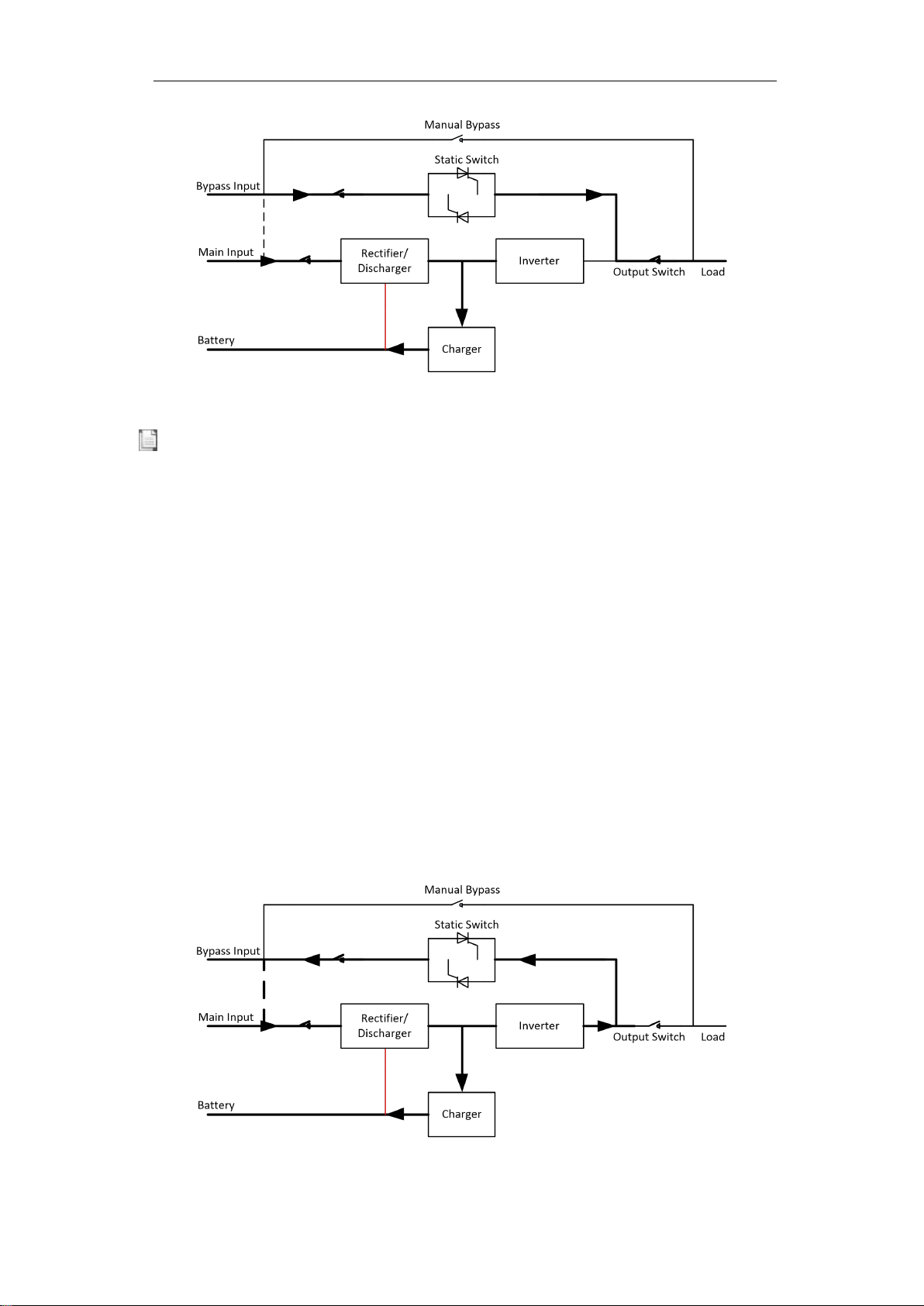
2.3.1 Normal Mode
The inverter of power modules continuously supply the critical AC load. The
rectifier/charger derives power from the AC mains input source and supplies DC
power to the inverter while simultaneously FLOAT or BOOST charging its associated
backup battery.

5
Fig 2-2 Normal mode operation diagram
2.3.2 Battery Mode
Upon failure of the AC mains input power, the inverter of power modules, which
obtain power from the battery, supply the critical AC load. There is no interruption in
power to the critical load upon failure. After restoration of the AC mains input power,
the “Normal mode” operation will continue automatically without the necessity of
user intervention.
Fig 2-3 Battery mode operation diagram
Note
With the function of Battery cold start, the UPS may start without utility. See more detail in
section 5.1.2.
2.3.3 Bypass Mode
If the inverter overload capacity is exceeded under Normal mode, or if the inverter
becomes unavailable for any reason, the static transfer switch will perform a transfer
of the load from the inverter to the bypass source, with no interruption in power to the
critical AC load. Should the inverter be asynchronous with the bypass, the static
switch will perform a transfer of the load from the inverter to the bypass with power
interruption to the load. This is to avoid large cross currents due to the paralleling of
unsynchronized AC sources. This interruption is programmable but typically set to be
less than 3/4 of an electrical cycle, e.g., less than 15ms (50Hz) or less than 12.5ms
(60Hz). The action of transfer/re-transfer can also be done by the command through
monitor.

6
Fig. 2-4 Bypass mode operation diagram
2.3.4 Maintenance Mode (Manual Bypass)
A manual bypass switch is available to ensure continuity of supply to the critical load
when the UPS becomes unavailable e.g. during a maintenance procedure. (See
Fig.2-5).
Fig .2-5 Maintenance mode operation diagram
Danger
During Maintenance mode, dangerous voltages are present on the terminal of input, output and
neutral, even with the LCD turned off.
2.3.5 ECO Mode
To improve system efficiency, UPS rack system works in Bypass mode at normal
time, and inverter is standby. When the utility fails, The UPS transfers to Battery
Mode and the inverter powers the loads.
7
Fig.2-6 ECO Mode operation diagram
Note
There is a short interruption time (less than 10ms) when transfer from ECO mode to battery mode,
it must be sure that the interruption has no effect on loads.
2.3.6 Auto-restart Mode
The battery may become exhausted following an extended AC mains failure. The
inverter shuts down when the battery reaches the End of Discharge Voltage (EOD).
The UPS may be programmed to “System Auto Start Mode after EOD”. The system
starts after a delay time when the AC mains input recovers. The mode and the delay
time are programmed by the commissioning engineer.
2.3.7 Frequency Converter Mode
By setting the UPS to Frequency Converter mode, the UPS could present a stable
output of fixed frequency (50 or 60Hz), and the bypass static switch is not available.
2.3.8 Self Aging Mode
If users want to burn in UPS without load, could set the UPS as Self Aging Mode, in
this mode, the current flow through rectifier, inverter, and back to input through
bypass. It needs only 5% loss to burn in UPS with 100% load.
Fig.2-7 self aging operation diagram

8
2.4 UPS Structure
2.4.1 UPS Configuration
The UPS configuration is provided in Table 2.1
Table2.1 UPS Configuration
Item
Components
Quantity
Remark
Standard Backup
Type(S)
Circuit Breakers
5
Standard
Dual Input
1
Standard
Parallel Card,
1
Optional
Dry Contact Card
1
Optional
Long Backup
Type(H)
Circuit Breakers
4
Standard
Dual Input
1
Standard
Parallel Card,
1
Optional
Dry Contact Card
1
Optional
2.4.2 UPS Outlook
The UPS outlook is shown as Fig.2-8 to Fig. 2-11.
Fig. 2-8 10-30kVA front appearance

9
Fig. 2-9 10/15 kVA back appearance (Long backup type)
Fig. 2-10 10-20kVA back appearance (Standard backup type)

10
Fig. 2-11 30kVA back appearance
Note
The Standard product is configured with single input; the dual-input option is available, with an
additional breaker for the main input.
Table2.2 UPS Configuration
Item
Description
1
The touch screen LCD
2
LED
3
Intelligent slot :SNMP
4
Cold start button, used to light up the LCD in battery mode
5
RS232 ,used to connect monitoring software
6
RS485, used to connect monitoring software
7
USB: B type, used to connect monitoring software
8
EPO
9
Parallel port: option
10
Dry contact: option
11
Maintenance bypass : surge protection
12
Bypass breaker: surge protection
13
Output breaker: surge protection
14
Input breaker: surge protection
15
Connection terminals and protective cover
16
GND
17
Battery breaker: surge protection

11
3. Installation Instruction
3.1 Location
As each site has its requirements, the installation instructions in this section are to act
as a guide for the general procedures and practices that should be observed by the
installing engineer.
3.1.1 Installation Environment
The UPS is intended for indoor installation and uses forced convection cooling by
internal fans. Please make sure there is enough space for the UPS ventilation and
cooling.
Keep the UPS far away from water,heat and inflammable and explosive, corrosive
material. Avoid installing the UPS in the environment with direct sunlight, dust,
volatile gases, corrosive material and high salinity.
Avoid installing the UPS in the environment with conductive dirt.
The operating environment temperature for battery is 20 ℃-25 ℃. Operating above
25℃will reduce the battery life, and operation below 20℃will reduce the battery
capacity.
The battery will generate a little amount of hydrogen and oxygen at the end of
charging; ensure the fresh air volume of the battery installation environment must
meet EN50272-2001 requirements.
If external batteries are to be used, the battery circuit breakers (or fuses) must be
mounted as close as possible to the batteries, and the connecting cables should be as
short as possible.
3.1.2 Site Selection
Ensure the ground or installation platform can bear the weight of the UPS
cabinet ,batteries and battery rack.
No vibration and less than 5 degree inclination horizontally.
The equipment should be stored in a room so as to protect it against excessive
humidity and heat sources.
The battery needs to be stored in dry and cool place with good ventilation. The most
suitable storage temperature is 20 ºC to 25ºC.
3.1.3 Size and Weight
The size of three dimensions and weight for the UPS cabinet is shown in Table 3.1.
Attention
Ensure there is at least 0.8m before the front of the cabinet so as to easily maintain the power
module and at least 0.5m behind for ventilation and cooling.
Table 3.1Size and Weight for the cabinet
Configuration
Size(W*D*H)
Weight
10kVA Long Backup Type
250*680*560mm
31kg
10kVA Standard Backup Type
250*680*560mm
82kg(20pcs 9AH Batteries Included)
15kVA Long Backup Type
250*760*700mm
33kg
15kVA Standard Backup Type
250*680*560mm
131kg(40PCS 7AH Batteries Included)

12
20kVA Long Backup Type
250*760*700mm
33kg
20kVA Standard Backup Type
250*680*560mm
145kg(40PCS 9AH Batteries Included)
30kVA Long Backup Type
250*800*650mm
42kg
30kVA Standard Backup Type
250*800*930mm
215kg(60PCS 9AH Batteries Included)
3.1.4 Installation Tools
DANGER
To ensure safety, installation tools for live operation shall be insulated.
Installation tools which may be used in installation process are shown in Table 3-2
and used as needed.
Table 3-2 Installation tools
Tool name
Main function
Tool name
Main function
Forklift
Handling
Nail hammer
Knock, install and remove
components
Herringbone
ladder
High-place operation
Rubber hammer
Knock and install
components
Clip-on ammeter
Detect current
Percussion drill, drill bit
Drill
Multimeter
Check electrical connection
and electrical parameters
Insulating tape
Electrical insulation
Cross screwdriver
Fasten screw
Heat-shrinkable tubing
Electrical insulation
Leveling
instrument
Leveling
Heat gun
Heat heat-shrinkable tubing
Insulated monkey
wrench
Tighten and loosen bolts
Electrician's knife
Wire stripping
Insulated torque
wrench
Tighten and loosen bolts
Cable tie
Bundle
Crimping pliers
Cc cold-pressed terminal
Leather working gloves
Protect operator’s hands
Hydraulic clamp
Clamp OT terminal
Antistatic gloves
Anti-static
Diagonal pliers
Shear cables
Insulating gloves
Insulation
Wire stripper
Wire stripping
Insulated protective
shoes
Protect operator
3.2 Unloading and Unpacking
3.2.1 Moving and Unpacking of the Cabinet
The steps to move and unpack the cabinet are as follows:
1. Check if any damages to the packing. (If any, contact to the carrier)
2. Transport the equipment to the designated site by forklift.
3. Unpack the package.
4. Remove the protective foam around the cabinet.
5. Check the UPS.
(a) Visually examine if there are any damages to UPS during transportation. If any,
contact to the carrier.
(b) Check the UPS with the list of the goods. If any items are not included in the
list, contact to our company or the local office.
6. Dismantle the bolt that connects the cabinet and wooden pallet after disassembly.
13
7. Move the cabinet to the installation position.
Attention
Be careful while removing to avoid scratching the equipment.
Attention
The waste materials of unpacking should be disposed to meet the demand for environmental
protection.
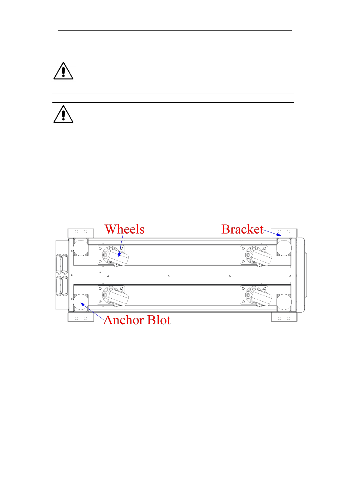
3.3 Positioning
3.3.1 Positioning Cabinet
The UPS cabinet has two way of supporting itself: One is to support itself temporarily
by the four wheels at the bottom,making it convenient to adjust the position of the
cabinet ;The other is by anchor bolts to support the cabinet permanently after
adjusting the position of the cabinet. The supporting structure is shown in Fig. 3-1.
Fig.3-1 Supporting structure(Bottom view)
The steps to position the cabinet are as follows:
1. Ensure the supporting structure is in good condition and the mounting floor is
smooth and strong.
2. Retract the anchor bolts by turning them counterclockwise using wrench, the
cabinet is then supported by the four wheels.
3. Adjust the cabinet to the right position by the supporting wheels.
4. Put down the anchor bolts by turning them clockwise using wrench, the cabinet is
then supported by the four anchor bolts.
5. Ensure the four anchor bolts are in the same height and the cabinet is fixed and
immovable.
6. Positioning done.
14
Attention
Auxiliary equipment is needed when the mounting floor is not solid enough to support the cabinet,
which helps distribute the weight over a larger area. For instance, cover the floor with iron plate or
increase the supporting area of the anchor bolts.
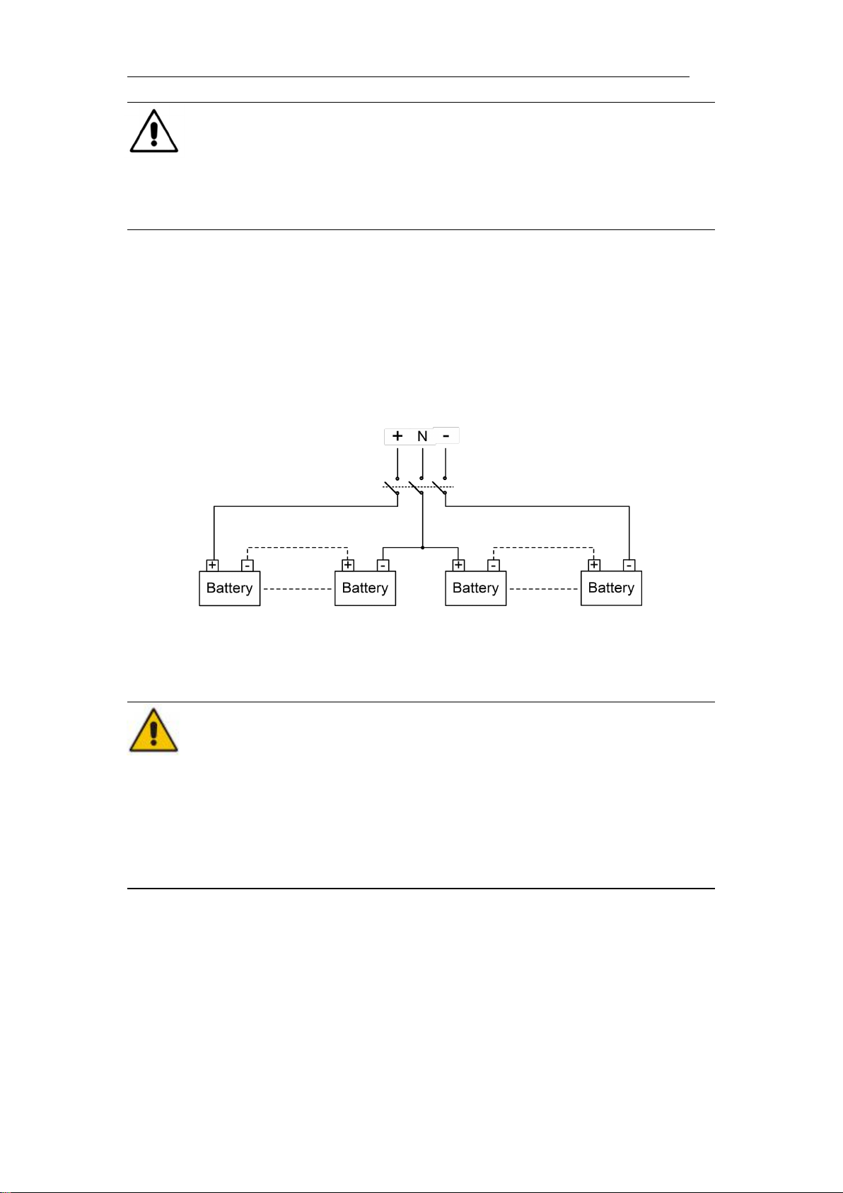
3.4 Battery
Three terminals(positive,neutral,negative )are drawn from the battery unit and
connected to UPS system. The neutral line is drawn from the middle of the batteries in
series (See Fig.3-2).
Select total number of batteries from 30 to 44 (even number), and the number of
positive and negative battery strings must be consistent. 10kVA could select the total
number 20pcs.
Fig 3-2 Battery string wiring diagram
Danger
The battery terminal voltage is of more than 200Vdc, please follow the safety instructions to avoid
electric shock hazard.
Positive and negative battery strings must be equipped with a 3-channel battery breaker with
limited current protection.
Ensure the positive, negative, neutral electrode is correctly connected from the battery unit
terminals to the breaker and from the breaker to the UPS system.
3.5 Cable Entry
Cables can enter the UPS cabinet from the bottom. Cable entry is made possible
through a blanking plate fitted at the bottom of the equipment. The cable entry is
shown in Fig.3-3.
Table of contents
Other Tescom UPS manuals

Tescom
Tescom DS300H-110 Series User manual

Tescom
Tescom LEO LCD 650 User manual

Tescom
Tescom AVR 11 User manual

Tescom
Tescom DS300HB Series User manual

Tescom
Tescom DXA3000 Series User manual

Tescom
Tescom DS310HA User manual

Tescom
Tescom DS310H User manual

Tescom
Tescom DS3100T User manual

Tescom
Tescom NEOLINE PRO 1kVAS User manual

Tescom
Tescom T-102 User manual

Tescom
Tescom CL110DR User manual

Tescom
Tescom DS360H User manual

Tescom
Tescom DS300T Series User manual

Tescom
Tescom DS3100 User manual

Tescom
Tescom DS300SHPA Series User manual

Tescom
Tescom MTI200 Series User manual

Tescom
Tescom DS3100HA User manual

Tescom
Tescom DS POWER SH User manual

Tescom
Tescom DS POWER H User manual

Tescom
Tescom CL110D User manual


