HEX H103A User manual

User Manual
Ver 1.0
www.HEX.co.kr
Photovoltaic Inverter
H103A


Hex Power System
H103A
1. Contents 1
1. Contents 1
2. Reference 2
3. Safety Precautions 3
4. Precaution for Use 6
5. Inverter System 7
6. Composition of Inverter 8
7. Installation of Inverter 11
8. Grid (AC) Connection 15
9. PV (DC) Connection 17
10. AC and DC Disconnection .20
11. Message .22
12. Test Operation .25
14. Warranty 27
13. Technical Data .26

Hex Power System
H103A
2. Reference
2
2. Reference
2.1 Overview
Thoroughly read this manual to safely and properly use the photovoltaic inverter.
Keep this manual in a place that is easily visible.
The purpose of this manual is to help you understand the maintenance and
operation procedures of the photovoltaic generation system and operate the
Hex Power grid-connected inverter.
When applying this manual to system operation, avoid uniform applications and
operate the facilities considering their importance, surrounding environment, and
conditions.
You are recommended to consult with the manufacturers when performing
regular inspections and services of major facilities and dangerous equipment.
2.2 Scope
This manual is applied to the H103A inverter of Hex Power System.

Hex Power System
H103A
3. Safety Precautions 3
3. Safety Precautions
3.1 Overview
You must comply with these safety precautions to prevent accidents and dangers,
operate the photovoltaic generation system stably, and use the inverter safely.
The inverter uses high voltage that can be fatal to people. Every repair
and service must be performed by certified service personnel. No part
inside the product may be serviced by the user.
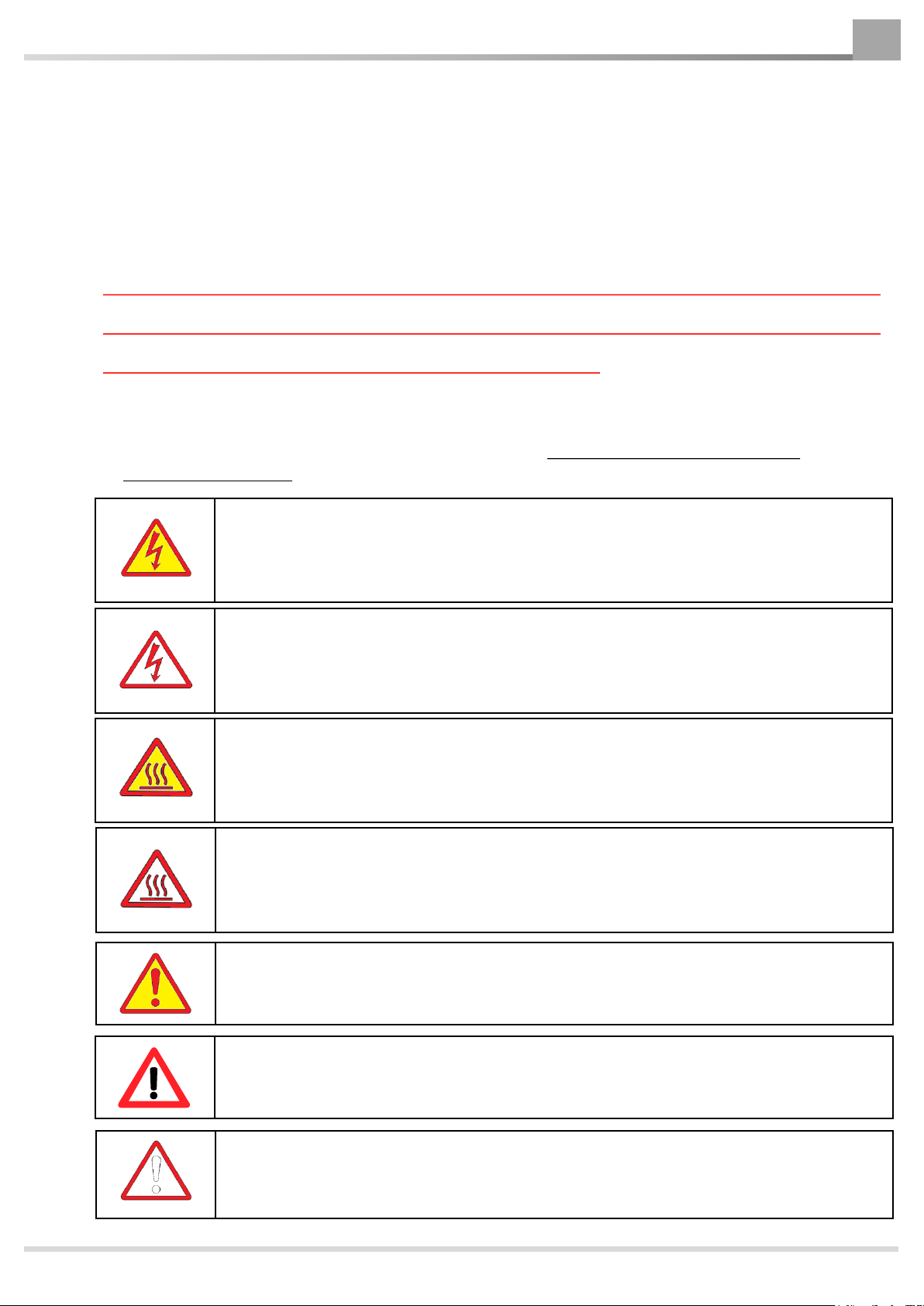
3.2 Warning Symbols
This manual uses the following warning symbols. Always refer to them during
maintenance work.
Danger
of Electric Shock !
This Danger of Electric Shock symbol applies to parts or tasks that involve
high voltage and high currents. Ignoring this warning may result in death
from electric shock.
Warning for Electric Shock !
This Warning for Electric Shock symbol applies to parts or tasks that are
exposed to the danger of fatal electric shock. Ignoring this warning may
result in serious injury or death from electric shock.
Danger of Burn
!
This Danger of Burn symbol applies to inverters that operate at high
temperatures. Ignoring this warning may result in serious injury or death
from burning.
Warning
for Burn !
This Warning for Burn symbol applies to tasks that are exposed to fatal
burns from the inverter. Ignoring this warning may result in serious injury
or death from burning.
Check
!
This symbol refers to the checkpoints that must be checked for the safe and
normal operation of the inverter.
Caution
!
This symbol applies to the operation or inspection of the inverter. Ignoring
this caution may result in mild injury or damage of the inverter
Warning
!
This part or task is exposed to fatal danger from the inverter. Ignoring this
warning may result in serious injury or death.

Hex Power System
H103A
3. Safety Precaution
4
3.3 Precautions
Danger
of Electric Shock!
This Danger of Electric Shock symbol applies to parts or tasks that involve
high voltage and high currents. Ignoring this warning may result in death
from electric shock.
Warning for Electric Shock!
This Warning for Electric Shock symbol applies to parts or tasks that are
exposed to the danger of fatal electric shock. Ignoring this warning may
result in serious injury or death from electric shock.
Danger of Burn!
This Danger of Burn symbol applies to inverters that operate at high
temperatures. Ignoring this warning may result in serious injury or death
from burning.
The inverter generates high heat during operation. Do not touch the inverter.
Warning for Burn!
This Warning for Burn symbol applies to tasks that are exposed to fatal
burns from the inverter. Ignoring this warning may result in serious injury
or death from burning.
Do not touch any part of the inverter through which high voltage and high currents flow.
-voltage and high-current
systems.
The inverter is always charged with high voltage even if it is stopped.
Internal inspection of the inverter is only permitted to people who have been trained for
inverter inspection.
-voltage terminals and
live parts may cause electric shock.
the switches with wet hands. It may cause electric shock.
Damaged cables of the inverter may cause fatal dangers such as electric shock or fire.
Even if the inverter has stopped, the inverter housing is hot. Only people who have been
trained for inspection may inspect the inverter.
result in burn.

Hex Power System
H103A
3. Safety Precaution 5
Warning
!
This part or task is exposed to fatal danger from the inverter. Ignoring this
warning may result in serious injury or death.
Some inverter parts are sharp or pointed. Touching them may result in serious injury
or death.
Caution
!
This symbol applies to the operation or inspection of the inverter. Ignoring
this caution may result in mild injury or damage of the inverter.
Only operate the inverter in a technically safe condition.
Operate the inverter only when no damage is detected by visual inspection.
The LCD of the operation panel may be damaged by static electricity. Please take caution.
Take special care when operating the input power and output power switches of the
inverter.
Check
!
This symbol refers to the checkpoints that must be checked for the safe and
normal operation of the inverter.
Every repair and service except daily checkups of the inverter must be always performed
by certified service personnel.
Turn off the input and output power supplies when there is any problem in inverter
operation. Otherwise, it may lead to a secondary accident.
Regularly perform visual inspection of the inverter for any damages.
Regularly check the operation status of the inverter.
Always use the inverter at an altitude below 1,000m.
For smooth operation of the inverter, the air inflow and discharge must be clear. Avoid
contaminated environment in which water, dusts or metallic foreign matters may flow in.
Install the inverter in a place that is easily accessible for service.

Hex Power System
H103A
3. Precautions for Use
6
4. Precautions for Use
4.1 Precautions for Transportation and Installation
Always transport in accordance with the transportation method stated on the
product box.
Pile up product boxes in accordance with the allowed number of piled boxes on the
box.
Do not put heavy objects on the product box.
Do not drop or give shock to the inverter.
Always follow the installation procedure detailed in this manual when installing the
inverter.
Always follow the wiring procedure detailed in this manual when wiring the inverter.
4.2 Installation Conditions
Installation Site : Outdoors
Storage and Operation Temperature : -20 50
Altitude : 1,500mor lower
4.3 Consideration for Installation
Abnormal vibrations, shocks or noise are accepted to a limit.
Using in a place where there are high iron contents.
Using in an environment with salt, high humidity, water accumulation, ice and snow,
mercury steam, chlorine gas, sulfuric acid gas, or other harmful gases.
Using in water or oil steams, or in explosive gases.
Exposure to a level of radiation that is higher than normal.
Rapid changes in temperature or humidity and exposure to strong electronic field.

Hex Power System
H103A
5. Inverter System 7
5. Inverter System
5.1 Photovoltaic Generation System
The H103A Photovoltaic Generation System converts the DC power of solar cells to
commercial AC power and supplies the AC power to loads and AC systems.
The power generation information can be watched from the monitoring system.
5.2 Inverter System
The H103A system consists of Boost Converter for the boosting of the photovoltaic
DC voltage and MPPT, Inverter for converting from DC to AC, Filter for removing
output noises, Controller for controlling the inverter, and HMI for displaying the
status.
Boost Converter DC/AC Inverter AC Filter
ControllerHMI
PV Input
DC
DC AC AC Output
Monitoring
System
Figure 5.1 Conceptual Diagram of Photovoltaic Generation System
Figure 5.2 Composition of Inverter System

Hex Power System
H103A
5. Composition of Inverter
8
6. Composition of Inverter
User Manual
6.1 Components of H103A Product
One H103A inverter, one copy of user manual, PV connector set + and -, one
connector for AC connection.
PV + Connector Set PV - Connector Set
Connector for AC Connection
H103A Photovoltaic Inverter

Hex Power System
H103A
6. Composition of Inverter 9
6.2 Inverter Size
(mm)

Hex Power System
H103A
6. Composition of Inverter
10
6.3 Exterior of Inverter
①LCD Display
②LED Display
③Nameplate
④System Connector Terminal
⑤Communication Connector Terminal
⑥PV + Connector Terminal
⑦PV –Connector Terminal
①
②
③
④
⑤
⑥⑦

Hex Power System
H103A
7. Installation of Inverter
7.1 Safety
7.2 Installation Site
Before deciding on an installation site, please check the following ;
Install the inverter on a solid surface such as concrete or metal wall.
The installation site must be always clean and the inverter must be accessible
safely without any aid. Otherwise, after-sales service may be limited.
Install the inverter at eye-level to facilitate the checking of operation status.
Install the inverter vertically on a wall or at an angle of up to 15.
Warning
!
This part or task is exposed to fatal danger from the inverter. Ignoring this
warning may result in serious injury or death.
Danger of Burn
!
This Danger of Burn symbol applies to inverters that operate at high
temperatures. Ignoring this warning may result in serious injury or death
from burning.
The inverter may catch fire even if it has been manufactured in a safe manner.
a place where combustible materials are stored.
7. Installation of Inverter 11

Hex Power System
H103A
7. Installation of Inverter
12
The AC and DC connectors must face downward. They must never face upward.
The inverter must not be inclined forward.
The inverter must not be inclined sideways.
The inverter must not be installed horizontally.
The ambient air temperature must not exceed 50and the inverter must not be
exposed to direct sunlight.
To prevent noise, do not install the inverter on a plaster board or similar walls that
may generate noise.
For sufficient heat discharge and after-sales service in the future, keep the minimum
clearance between inverters or between the inverter and other objects.
Minimum clearance of inverter

Hex Power System
H103A
7.3 Installation of Inverter on Wall
1. Before installing the inverter, mark drill holes or connecting screw holes on the wall.
When installing the inverter with three holes, make two connecting screws or drill
holes at the top and one hole at the bottom as shown in A.
When installing the inverter with two holes, make one connecting screw or drill
hole at the top and hole at the bottom as shown in A.
7. Installation of Inverter 13
Installing the inverter With 3 holes
432.5mm (Installing the inverter with 3 holes
A
)
2. Fix screw about two thirds of the screw length.
(for concrete wall, mount anchor bolts (M6) and fix
with nuts. For metal wall, use connecting screws)

Hex Power System
H103A
7. Installation of Inverter
14
3. Lift the inverter slightly and insert bolt into
the top fixing pin to fix the inverter.
①②
③
4. Tighten bolt in the top fixing pins and a bolt
between the bottom pins
5. Finish the inverter installation as shown
in the figure.

Hex Power System
H103A
8. Grid(AC) Connection 15
8. Grid (AC) Connection
8.1 Safety
Each inverter must have an individual circuit breaker to safely separate the inverter
in the event of overloads.
Warning
!
This part or task is exposed to fatal danger from the inverter. Ignoring this
warning may result in serious injury or death.
There is a danger of death from fire. Connecting two or more inverters to the same
circuit breaker can not guarantee the protection function of the circuit breaker and the
cable may catch fire or the inverter may be damaged as a result.
Never connect multiple inverters to the same circuit breaker.
Warning
!
This part or task is exposed to fatal danger from the inverter. Ignoring this
warning may result in serious injury or death.
circuit breaker can not guarantee the protection function of the circuit breaker and a fire
may break out as a result.
No consumer electronic devices may be connected between a circuit breaker and
inverter.

Hex Power System
H103A
8. Grid(AC) Connection
16
8.2 AC Connection Method
To connect to an inverter, the supplied AC plug connector must be attached to an AC cable.
You can assemble the AC plug connector in the following sequence. There are L, N, Ground
Marks on the AC connector. Connect L to the L-phase, N to N-phase and Ground to the
Ground to the ground wire(Take special care about the L and N connections)
L
N
Cable Condition
Use 4SQ or higher HIV cables.
Procedure
1. Uncover the cable, insert the plug, and fasten
with a screwdriver.
2. Push the connector and plug until it clicks into
place and fasten the screw joint at the bottom.
3. When the assembly of the AC cable and AC plug
cable connector is completed, insert the AC connector
of the inverter until it clicks into place as shown in the
figure
Warning
!
The Ground must be connected
to a ground wire.
Ground

Hex Power System
H103A
9. PV(DC) Connection 17
9. PV (DC) Connection
9.1 Inverter Connection
Connect the module to the inverter as
shown in the figure, taking care not to
change the+ and poles. Connect the
other string in the same way.
Conditions of PV Module Strings
Use the same type of modules.
Use the modules of the same
manufacturer.
Use the same module arrangement.
Set the same module slope.
9.2. Connection of DC Connector
To connect the inverter, the DC plug connector must be attached to the connection
Cable of the PV module.
Assemble the DC plug connector in the following sequence. Make sure that the
+ connector is connected with the + wire and the connector with the wire.

Hex Power System
H103A
9. PV(DC) Connection
18
Cable Connections
Use 6SQ or higher HIV cables.
Procedure
1. Insert the uncovered cable into the pin connector and compress it. Make sure
that the + cable is connected to the + pin and the cable to the pin.
.
.
2. Push the cable connected to the pin into the plug until it clicks into place.
Compress
Compress
Table of contents
Popular Inverter manuals by other brands

SolaX Power
SolaX Power ZDNY Series user manual

Mitsubishi Heavy Industries
Mitsubishi Heavy Industries SRR25ZM-S Technical manual

Epever
Epever IP1500-Plus Series user manual

SOLINTEG
SOLINTEG M Series user manual

Eaton
Eaton Cutler-Hammer SPI9000 user manual

Turbo Energy
Turbo Energy Lithium Series instruction manual