Hexagon HxGN MineProtect OAS-LV 202 Assembly instructions

HxGN Mine Operator Alertness
System – Light Vehicles
User Reference Manual
Version No. 3.0
Issued February 2020
English
MINING SAFETY

ii © Hexagon Mining
HxGN Mine Operator Alertness System –Light Vehicles User Reference Manual
This document and any information or descriptive matter contained therein is communicated in confidence and is
the copyright property of Hexagon Mining. Neither the whole, nor any extract may be disclosed, loaned, copied, or
used in manufacturing or tendering purposes without their written consent.
© Copyright 2020 Hexagon Mining. All rights reserved. Hexagon Mining is part of Hexagon. Hexagon Mining and
the Hexagon Mining logo are the registered trademarks of Hexagon Mining. All trademarks or service marks used
herein are property of their respective owners. Hexagon Mining makes no representation or warranty regarding
the accuracy of the information in this publication. This document gives only a general description of the product(s)
or service(s) offered by Hexagon Mining and, except where expressly provided otherwise, shall not form part of
any contract. Such information, the products and conditions of supply is subject to change without notice.
Disclaimer: Illustrations, descriptions, and technical specifications in this document are not binding and are subject
to change without notice.
This document is optimized for printing on Letter paper.

©Hexagon Mining iii
Revision History
Date
Document
Version
Software
Version
Author
Revision
20 Feb 2020
1.0
Marco
Carvalho
Manual Initial Version
06 Mar 2020
2.0
Gustavo
Severino
Adding the MPE Calculations,
Label Variants, adding all units
13 Apr 2020
3.0
Gustavo
Severino
Updating the Labels,
statements to ANATEL and
NOM/IFT compliance and the
item 3.2 with the RF Exposure
Caution.

iv © Hexagon Mining
Table Of Contents
1Document Introduction .............................................................................6
1.1 Contacting Support......................................................................................................6
1.2 Document Conventions ...............................................................................................6
2Overview.....................................................................................................7
2.1 System Information......................................................................................................7
2.1.1 HxGN Mine Protect OAS-LV models 202, 204, 211 and 280...........................7
2.1.2 OAS-LV Features..............................................................................................7
2.1.3 Cellular Modem Specs ...................................................................................... 8
2.1.3.1 Model 202 –Cellular modem specs.......................................................... 8
2.1.3.2 Model 204 –Cellular modem specs.......................................................... 8
2.1.3.3 Model 211 –Cellular modem specs.......................................................... 8
2.1.3.4 Model 280 –Cellular modem specs.......................................................... 8
2.1.4 OAS-LV System Diagram..................................................................................8
2.2 Connector Description.................................................................................................9
2.2.1 Connector Identification.....................................................................................9
2.2.2 Connector Interface Description........................................................................ 9
2.3 Multifunction LED.......................................................................................................10
2.3.1 LED Indicator Light Location...........................................................................10
2.3.1.1 LED Identification.....................................................................................10
2.3.1.2 LED Status and Error Codes...................................................................10
2.4 Speaker .....................................................................................................................11
2.5 Label..........................................................................................................................15
2.5.1 Label Location.................................................................................................15
2.5.2 Label Content and Layout...............................................................................15
2.5.3 Label Examples...............................................................................................16
2.5.3.1 FCC Certification Labels..........................................................................16
2.5.3.2 CE Certification Labels............................................................................16
2.5.3.3 RCM Certification Labels.........................................................................17
3Hardware Installation...............................................................................18
3.1 Before Installation......................................................................................................18
3.2 OAS-LV Module Installation ......................................................................................18
3.2.1 Power Cable Installation..................................................................................18
3.2.1.1 Installation using Cigarette Plug.............................................................. 18
3.2.1.2 Regular installation..................................................................................19
3.3 Antenna Installation...................................................................................................19
3.3.1 GNSS Antenna Application.............................................................................19
3.3.2 GNSS Antenna Installation.............................................................................. 20
3.4Connection to Additional Sensors or devices............................................................20
3.5 Upgrade Software......................................................................................................20
4Care and Transport..................................................................................20
4.1 Transport ...................................................................................................................20
4.2 Storage......................................................................................................................20
4.3 Cleaning and Drying..................................................................................................20
4.3.1 Product and Accessories.................................................................................20
4.3.2Connectors and Plugs..................................................................................... 20
5Safety Directions .....................................................................................21
5.1 General Introduction..................................................................................................21

©Hexagon Mining v
5.2 Intended Use..............................................................................................................21
5.2.1 Permitted Uses ................................................................................................21
5.2.2 Adverse Use ....................................................................................................21
5.3 Limits of Use ..............................................................................................................21
5.3.1 Environment.....................................................................................................21
5.4 Responsibilities ..........................................................................................................22
5.4.1 Manufacturer of the Product............................................................................22
5.4.2 Manufacturers of Non-Hexagon Mining Accessories ......................................22
5.4.3 Persons in Charge of the Product ...................................................................22
5.5 Hazards of Use ..........................................................................................................22
5.5.1 General Hazards..............................................................................................22
5.5.2 Mechanical Hazards ........................................................................................22
5.5.3 Lightning Hazards............................................................................................23
5.5.3.1 Lightning Conductors ...............................................................................23
5.5.4 Disposal...........................................................................................................23
5.6 Electromagnetic Compatibility (EMC) ........................................................................24
6Technical Data..........................................................................................25
6.1 Design........................................................................................................................25
6.1.1 User Interface ..................................................................................................25
6.1.2 Dimensions......................................................................................................25
6.1.3 Weight..............................................................................................................25
6.1.4 Power Supply...................................................................................................25
6.2 Interfaces ...................................................................................................................25
6.3 Environmental Specifications.....................................................................................26
6.3.1 Temperature ....................................................................................................26
6.3.2 Vibration...........................................................................................................26
6.4 FCC Statement (Applicable for U.S.).........................................................................26
6.5 ANATEL Statement (Applicable for Brazil) ................................................................26
6.6 IFT Statement (Applicable for Mexico).......................................................................26
7Appendix A –Connector Pinout .............................................................27
8Appendix B: FCC Maximum Permissible Exposure Calculations........28
8.1 OAS-LV Intentional Radiators....................................................................................28
8.1.1 Wi-Fi.................................................................................................................28
8.1.2 GSM (LTE, 4G)................................................................................................28
8.2 MPE Calculations.......................................................................................................28
8.2.1 MPE Formula...................................................................................................28
8.2.2 Wi-Fi MPE Calculations...................................................................................28
8.2.2.1 2400 to 2500 MHz..................................... Error! Bookmark not defined.
8.2.2.2 4900 to 5900 MHz..................................... Error! Bookmark not defined.
8.2.3 GSM (LTE, 4G) MPE Calculations ................... Error! Bookmark not defined.
8.2.3.1 GSM 300 to 1500 MHz.............................. Error! Bookmark not defined.
8.2.3.2 GSM 1.5 GHz to 2.7 GHz.......................... Error! Bookmark not defined.
8.2.4 Simultaneous Transmission (WLAN and GSM) MPE
Calculations ...................................................... Error! Bookmark not defined.
9Glossary....................................................................................................31
6 © Hexagon Mining
1 Document Introduction
The HxGN Mine Operator Alertness System –Light Vehicles User Reference Manual is part of Hexagon
Mining’s Documentation Suite.
This manual is intended to serve as a guide to the Mine Operator Alertness System –Light Vehicles (OAS-
LV) module. This manual provides all instructions required to operate the OAS-LV product to a basic level.
This manual provides an overview of the system together with the care and transport, technical data, and
safety directions.
It is assumed a person using this manual is familiar with:
⚫Site-specific safety procedures, Safe Work Procedures (SWPs) and Standard Operating Procedures
(SOPs).
⚫Electrical installation processes and procedures.
⚫Hardware installation processes.
⚫Hexagon Mining equipment installation.
Note
The document uses generic images to show general layout and generic information for various
procedures. The site-specific screen layout, menu, and procedure information may vary from what
is displayed in the manual.
1.1 Contacting Support
For all Hexagon Mining product support:
Contact Method
Details
Web portal
https://hexagonmining.com/customer/portallogin
1.2 Document Conventions
This document uses basic conventions to indicate actions:
Convention Example
Description
Select FILE > PRINT
Menu selections, buttons, and icons appear in bold text. In this case, select
the FILE menu and the PRINT option. Location and capitalization of menu
items may vary by mine site.
Ctrl+P
Keyboard shortcut keys. The example indicates to select and hold down the
Ctrl key and select the P key.
See xxx
Refer to
“See” indicates a reference to another section of this document.
“Refer to” indicates reference to another document.
WARNING
Warnings alert the user to dangerous procedures which could cause injury or
death.
CAUTION
Cautions alert the user to dangerous procedures which could cause damage
to equipment.
Note
Notes supply important information about a procedure which is not covered
in the procedure text.

©Hexagon Mining 7
2 Overview
The HxGN Mine Protect OAS-LV embedded module computer serves as an on-machine integrated Fatigue
Monitor application module. It detects and monitor Fatigue patterns using a camera in real-time position
through GNSS. It can store fatigue events information and communicates back to a central server using
integrated vehicle Wi-Fi or cellular networks. The camera can detect and track fatigue patterns even in harsh
conditions like in the dark due to IR illuminators installed in the module.
Note
The images used in this manual are for reference purposes only; individual screens and icons may
differ from the actual items.
This product is intended for Professional Use only.
HxGN Mine Protect OAS-LV is industrial solution targeting to light vehicles.
2.1 System Information
2.1.1 HxGN Mine Protect OAS-LV models 202, 204, 211 and 280
The OAS-LV module consists of an 2GHz Quad-core, ARM Cortex-A53TM plus 400MHz Cortex-M4TM real-
time processor, an internal GNSS receiver, USB port, USB OTG (Ethernet driver), enabling it to serve as
monitor fatigue device for data transfer to a central server via Wi-Fi and/or a Cellular network.
The OAS-LV unit is identified by its black base
2.1.2 OAS-LV Features
All OAS-LV modules share these features:
⚫One GNSS module (L1 GPS/GLONASS/BeiDou). (1 x SMA connector for external antenna)
⚫One WI-FI/BT Integrated module
⚫One 4G LTE Module configured to operate according to some specific bands
⚫One Power Input port w/ignition sense (9V-32 VDC, 5W)
⚫Two USB 2.0, 480 Mbit port, available in Micro USB (OTG) and Mini-USB connectors
⚫One Micro SD memory card interface supporting 64 GB of data
⚫Two integrated speakers
⚫Four IR Illuminators
⚫Digital Camera with optical size of 1/4" and 5 Megapixel.
⚫Multicolor LED
⚫SIM card holder to support 4G LTE cellular communication.
⚫One internal 3-axis accelerometer.
⚫Multi-Function Push Button switch

8 © Hexagon Mining
2.1.3 Cellular Modem Specs
CAUTION
The 4G SIM card must be a data SIM, and data must be activated on the carrier’s network.
Voice-only networks won’t carry the data.
Note
Data charges may apply. Due to the activity on the networks, unlimited data contracts are
suggested to avoid extra data charges.
2.1.3.1 Model 202 –Cellular modem specs
One Cellular Modem (4G LTE, 3G UTMS)
⚫LTE –Band 2, 4, 5,12 and UTMS Band 5 and Band 2
2.1.3.2 Model 204 –Cellular modem specs
One Cellular Modem (4G LTE)
⚫LTE –Band 4, 13
2.1.3.3 Model 211 –Cellular modem specs
One Cellular Modem (4G LTE, 2G GSM/GPRS)
⚫LTE –Band 3, 7, 20 and E-GSM 900MHz and DCS 1800MHz
2.1.3.4 Model 280 –Cellular modem specs
One Cellular Modem (4G LTE, 3G UTMS)
⚫LTE –Band 3, 8, 28 and UTMS Band 1
2.1.4 OAS-LV System Diagram

©Hexagon Mining 9
2.2 Connector Description
2.2.1 Connector Identification
The OAS-LV has a connector identification according to the picture below.
2.2.2 Connector Interface Description
A description of the interfaces is listed in the following table:
Connector/Device
name
Connector/Device
specification
Label Name
Interface
Power Connector with
Locking Pin
Micro-Fit, 4POS, 3MM,
Dual Row
PWR
9-32V DC power in,
ignition sense input
Micro-SD
Micro-SD Memory card
connector, Push-Push
SD
USB OTG
Micro USB, Receptacle,
5POS, Type B
OTG
USB OTG connection to
interface to external
devices (examples)
USB Host
Mini USB, Receptacle,
5POS, Type B
HOST
USB Host connection to
interface to external
devices (examples??)
Sim Card
Micro SIMM Card
connector, Push-Push
SIM
Cellular carrier SIM card
interface
Push Button
Push Button Switch
PB
Push Button Switch to
control Wi-Fi operation
mode
External GPS
Antenna
SMA, Female
-
External GPS Antenna
10 © Hexagon Mining
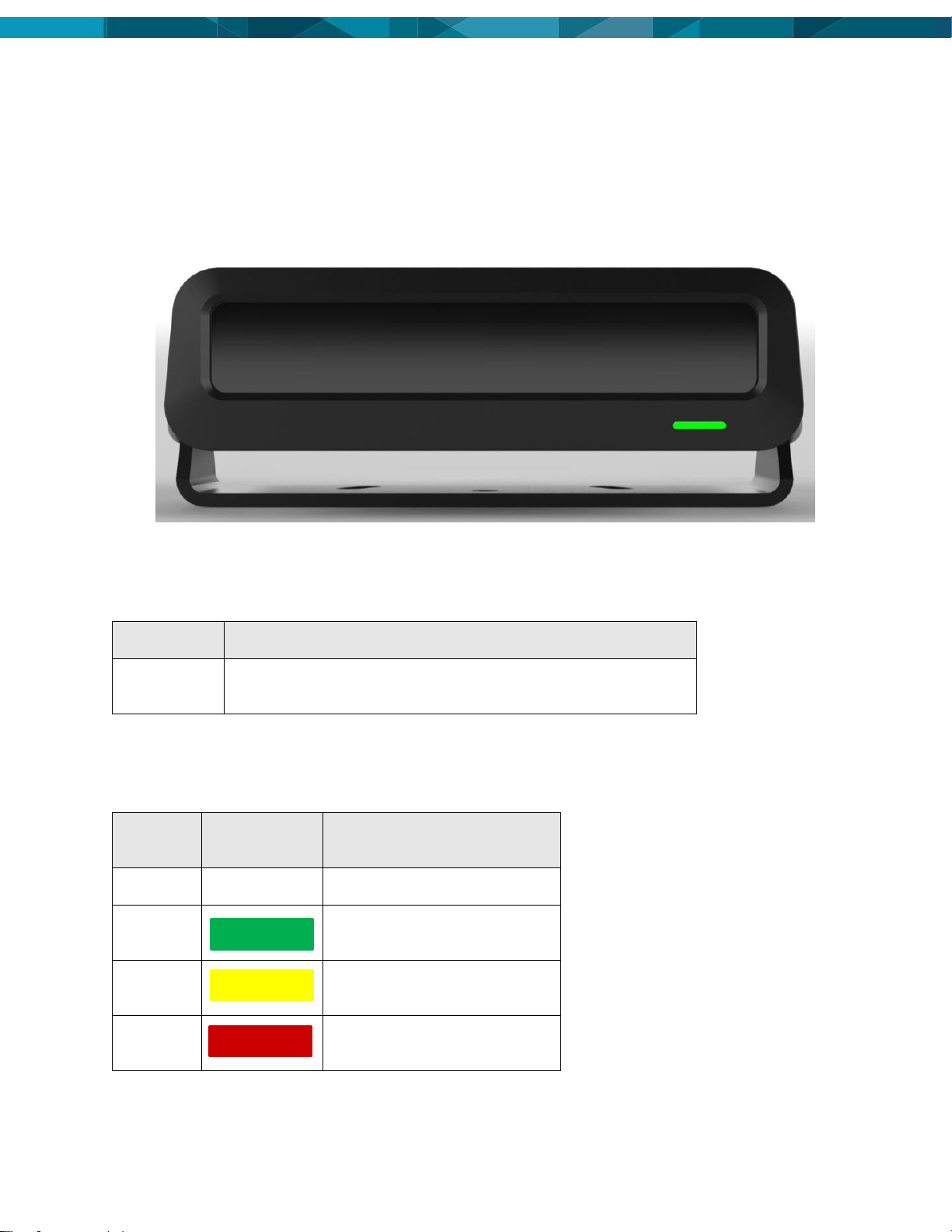
2.3 Multifunction LED
The LED on the front of the OAS-LV indicate the status of the module for different working and error
conditions
2.3.1 LED Indicator Light Location
The LED indicator light is located on the front of the module in right side. Picture below indicate the LED turned
on in green.
2.3.1.1 LED Identification
There is one external LED indicator light on the OAS-LV module. It is a multicolor led that can show different
status or Error coders for the unit. See 2.3.1.2 LED Status and Error Codes below for more information on the
displayed light patterns.
LED
Function
Multicolor
LED
The LED can show different status and codes with will indicate
how it is working.
2.3.1.2 LED Status and Error Codes
The Multicolor LED indicates different status for Power, GPS signal, Wi-Fi power and status of the unit during
boot up and regular operation. Details of the LED status codes are shown below:
State
LED
Color/Status
Notes
Power off
Turned off
System running, or powered off
Booting
process
Initial on-boot
Flashing
Yellow
Starting up or loading software
from microSD
System
Failure
System failure, typically GPS
not available
BLINK
BLINK
BLINK

©Hexagon Mining 11
State
LED
Color/Status
Notes
Wi-Fi
Hotspot
Wi-Fi hotspot enabled
2.4 Speaker
The system is composed by two speakers which provides audio messages to the operator.
Currently the following messages are provided in English.
Message Description
Audio Message
"blocked_camera"
"camera has been obstructed"
"bluetooth_connected"
"bluetooth connected"
"bluetooth_disconnected"
"bluetooth disconnected"
"braking_event"
"hard braking detected"
"burn_in"
"system burn in mode"
"caution"
"proximity alert"
"caution_front"
"caution, front"
"caution_front_left"
"caution, front left"
"caution_front_right"
"caution, front right"
"caution_rear"
"caution, rear"
"caution_rear_left"
"caution, rear left"
"caution_rear_right"
"caution, rear right"
"collision"
"collision alert"
"collision_stop"
"collision alert, stop"
"collision_slow_down"
"collision alert, slow down"
"cornering_event"
"hard cornering detected"
"dispatch_1"
"please contact dispatch"
"distraction_1"
"distraction noticed, please keep your eyes on
the road"
"distraction_2"
"distraction alert"
BLINK

12 © Hexagon Mining
Message Description
Audio Message
"distraction_3"
"caution, concentrate on the road"
"fatigue_1"
"fatigue alert"
"fatigue_2"
"if you are fatigued, please contact your
supervisor"
"fatigue_3"
"if you are fatigued, please contact dispatch"
"fatigue_4"
"stay alert, call dispatch if you are tired"
"fatigue_5"
"if you feel sleepy, call dispatch or your
supervisor"
"fatigue_6"
"caution, if you feel tired call your supervisor"
"fatigue_look_down"
"fatigue alert, looking down"
"focused_1"
"stay focused, if you are tired get dispatched to
change room"
"focused_2"
"stay focused, concentrate on the road"
"following_dist"
"following distance breached"
"front"
"front"
"goodbye"
"goodbye"
"gps_error"
"GPS offline"
"heavy_machinery"
"heavy machinery"
"hello"
"hello"
"id_not_found"
"operator ID not found"
"id_not_found_2"
"your operator ID cannot be found"
"illuminator_ok"
"IR illuminator OK"
"light_vehicle"
"light vehicle"
"left"
, "left"
"logged_in"
"logged in"
"logged_off"
"logged off"
"mesh_network_ok"
"mesh network, OK"

©Hexagon Mining 13
Message Description
Audio Message
"oas_init"
"operator alertness system initialized"
"no_face"
"the fatigue sensor cannot see your face,
please call DISPATCH now"
"no_face_2"
"the fatigue sensor cannot see your face"
"no_operator"
"no operator is currently logged in"
"no_sound"
"I can't say that"
"on_boot"
“welcome aboard, your fatigue management
system is operational"
", "on_boot_2"
"your fatigue management system is ready"
"on_login"
"you are logged in"
"on_login_failed"
"operator ID not found"
"on_logoff"
"you are logged off"
"overspeed"
"overspeeding alert, slow down"
"pedestrian_1"
"pedestrian alert, slow down"
"pedestrian_2"
"pedestrian alert, stop"
"pedestrian_3"
"pedestrian alert"
"phone_detected"
"cellular phone detected"
"please_login"
please login"
"proximity"
"proximity alert"
"radar_1"
"radar alert, slow down"
"radar_2"
"radar alert, stop"
"radar_3"
"radar alert”
"rear"
"rear"
"right"
"right"
"speed_1"
"speeding alert, please slow down"
"speed_2"
"speeding alert"
"speed_3"
"caution, your speed is too high"

14 © Hexagon Mining
Message Description
Audio Message
"supervisor_1"
"please contact your supervisor"
"system_failed"
"your fatigue system is not yet operational"
"system_ok"
"your fatigue system is fully operational"
"system_shutdown"
"your fatigue system is shutting down"
"warning"
"collision alert"
"warning_front"
"warning, front"
"warning_front_left"
warning, front left"
"warning_front_right"
"warning, front right"
"warning_rear"
"warning, rear"
"warning_rear_left"
"warning, rear left"
"warning_rear_right"
"warning, rear right"
"welcome"
"welcome"
"wifi_ok"
"wireless network is online"
"wifi_start"
"Wi-Fi hotspot enabled"
"wifi_stop"
"Wi-Fi hotspot disabled"
"seatbelt"
"please fasten your seatbelt"
"format_sdcard"
"formatting backup video storage"
©Hexagon Mining 15
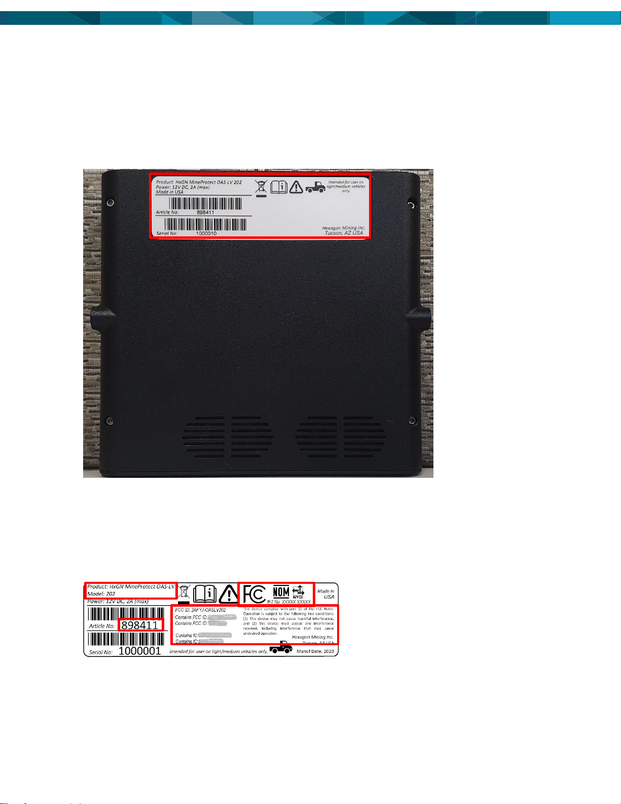
2.5 Label
2.5.1 Label Location
The product has just one label were all information related to the product can be found. The label is located at
the back of the unit like shown in the picture attached.
The Product label on the base of the module lists: Description, Power Requirement, Article Number, Serial
Number, Company name and where Manufactured.
2.5.2 Label Content and Layout
The label layout is the same for all variants available. The information will change according to the article
number and its certifications.
⚫Product: HxGN MineProtect OAS-LV
⚫Model: 202, 204, 211, 280
⚫Article Number: 898411, 905058, 905059, 905060
⚫Compliance requirements: FCC, IC, CE, ANATEL, NOM, IFT, ICASA, RMC
16 © Hexagon Mining
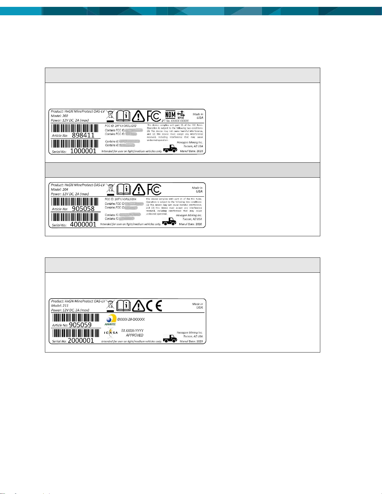
2.5.3 Label Examples
2.5.3.1 FCC Certification Labels
Model: 202
Note
This model includes the NOM Certification.
Model: 204
2.5.3.2 CE Certification Labels
Model: 211
Note
This model includes ANATEL Certification and ICASA Certification.

©Hexagon Mining 17
2.5.3.3 RCM Certification Labels
Model: 280
Note
This model includes R-NZ Certification.

18 © Hexagon Mining
3 Hardware Installation
3.1 Before Installation
Installation requires specialized knowledge and must be installed by a Hexagon Mining Authorized Installer.
Hexagon Mining recommends that installation of the OAS-LV equipment be performed by a qualified
technician.
The average installation time varies, and the time of installation will be dependent on vehicle type and options
purchased.
For OAS-LV module safety and installation instructions refer to the HxGN Mine Discover OAS-LV Installation
Manual.
WARNING
All Hexagon Mining Equipment must be installed by qualified installation personnel.
CAUTION:
During any welding on the machine, the OAS-LV module must be completely isolated from
the machine by disconnecting all its cables including power, I/O, and RF cables. Welding
can cause large ground currents, which may damage internal electronic components of the
OAS-LV module or its GPS antenna. The OAS-LV module is not warranted for damage when
connected during welding activities.
⚫Install the system in a clean and dry workshop environment. Failure to do so may cause the system to
short or promote product malfunction.
⚫Route and secure all cables and wiring to ensure that they do not rub, causing premature failure.
3.2 OAS-LV Module Installation
CAUTION
RF Exposure: OAS-LV has internal antennas and must be mounted more than 20 cm away
from the human body.
WARNING
Do not mount the OAS-LV where it may obscure the driver’s view of the road or field.
Do not mount the OAS-LV where it may be struck by a deploying airbag.
For OAS-LV module safety and installation instructions refer to the HxGN Mine Discover OAS-LV Installation
Manual.
3.2.1 Power Cable Installation
For OAS-LV module safety and installation instructions refer to the HxGN Mine Discover OAS-LV Installation
Manual.
WARNING
Always ensure the power supply cable is connected at the 9-32V DC power supply source
on the vehicle through a fuse rated no higher than 3A. Failure to do so may result in damage
to the equipment and/or fire.
CAUTION
The OAS-LV unit is a 9-32-volt DC (negative-to-earth) system only. Connecting to a positive-
to-earth system will cause damage, which is not covered by warranty.
There are two ways to connect the power cable to the vehicle:
⚫Cigarette plug
⚫Regular Installation
3.2.1.1 Installation using Cigarette Plug
1. Make sure the vehicle cigarette socket supplies a voltage in the range from 9 to 32V DC.

©Hexagon Mining 19
2. Connect the cigarette plug connector side in the supplied power cable to the vehicle cigarette socket
3. Route and secure all cables and wiring to meet Hexagon Mining requirements and ensure that there is
no rubbing, which can cause premature failure.
4. Connect the other side of the power cable in the OAS-LV unit. Make sure the cable connector will lock in
the OAS-LV Power connector.
3.2.1.2 Regular installation
1. Connect the supplied power cable to a reliable power source, for example, the vehicle’s main power
system.
2. Connect the red wire to a 9-32-volt positive, 3A fused power source, capable of delivering a constant 5A.
3. Connect the black wire to the vehicle’s earth.
4. Connect the blue wire to a 9-32-volt positive, 5A fused source that is active (positive voltage) when the
vehicle’s ignition key is turned to the “ON” position.
5. Route and secure all cables and wiring to meet Hexagon Mining requirements and ensure that there is
no rubbing, which can cause premature failure.
6. Connect the other side of the power cable in the OAS-LV unit. Make sure the cable connector will lock in
the OAS-LV Power connector.
3.3 Antenna Installation
3.3.1 GNSS Antenna Application
To ensure correct antenna application, refer to the Antenna Application table.
WARNING
Only antenna listed in the Antenna Application table are permitted to be used. If higher
powered antennas are used, injury to personnel may occur.
WARNING
The Wi-Fi antennas must be mounted more than 30cm away from the operator.
CAUTION
Only antenna cables provided with the OAS-LV module equipment for installation, and as
identified in the specific OAS-LV module installation diagrams are to be used in OAS-LV
module antenna installations to ensure optimal performance and meet regulatory
requirements.
GNSS Antenna Application
Module
Required Antenna: Hexagon Mining Part Number
OAS-LV
GNSS: 913422

20 © Hexagon Mining
3.3.2 GNSS Antenna Installation
CAUTION
Antennas must be mounted more than 20 cm away from any other antenna.
CAUTION
The OAS-LV GNSS Antenna must be mounted with a clear view of the sky and free from any
obstruction from machine components.
Note
Read all instructions prior to assembly and installation.
The OAS-LV GNSS Antenna must be mounted with a clear view of the sky and free from any obstruction from
machine components and must meet the following criteria.
1. The OAS-LV GNSS Antenna must be on the flat level part of the machine or mast.
2. Route the cables through the existing grommets if possible; if not, modification may be required to route
the cables to the required location. If creating a new entry point, use a grommet to protect the cables.
3. The cables must not be cut, kinked, or bent tightly, as it degrades performance and a system failure may
result.
4. Cables must be routed neatly back to the OAS-LV.
3.4 Connection to Additional Sensors or devices
For connection to all additional sensors and interfaces refer to machine specific installation manuals.
3.5 Upgrade Software
New versions of software may be installed on the OAS-LV module from either a USB Flash Drive or by using
Hexagon’s web-based software configuration tool. Please consult the Hexagon Mine Protect OAS-LV
Configuration manual for detailed instructions regarding how to update software on the OAS-LV module.
4 Care and Transport
4.1 Transport
When transporting the product by rail, air, or sea, always use the complete original Hexagon Mining
packaging, cardboard box, or an equivalent, to protect the product against shock and vibration.
4.2 Storage
Ensure the temperature limits are followed when storing the equipment, particularly in summer if the
equipment is inside a vehicle. Please reference the Technical Data section for information about temperature
limits.
4.3 Cleaning and Drying
4.3.1 Product and Accessories
Use only clean, soft, lint-free cloth for cleaning. If necessary, moisten the cloth with water or pure alcohol. Do
not use other liquids; these may attack the polymer components.
4.3.2 Connectors and Plugs
Keep plugs clean and dry. Blow away any dirt lodged in the plugs of the connecting cables.
This manual suits for next models
7
Table of contents
Other Hexagon Security System manuals


