Heyl Neomeris Testomat 2000 V User manual

1
Testomat 2000®V
Mixing controller for water
hardness 1.0-10.0 / 2.5-25.0 °dH
and carbonate hardness
1.0 –20.0 °dH
Operating Instructions

Content
2
Content
Content.................................................................................................2
Important safety information .............................................................4
Intended use .........................................................................................4
Qualification of the staff ........................................................................4
Warning notices in these instructions ...................................................5
Further documents................................................................................5
Pay particular attention to .....................................................................5
General instructions..............................................................................5
Installation.............................................................................................6
Operation ..............................................................................................6
After switch-off and longer downtime....................................................6
Cleaning................................................................................................6
De-installation .......................................................................................6
Disposal ................................................................................................6
Scope of delivery ................................................................................7
Performance specifications...............................................................7
Indicators for Testomat 2000®V...........................................................8
Function ................................................................................................8
Analysis cycle and control process.......................................................8
Requirements........................................................................................9
Special setting options..........................................................................9
Reaction during fault.............................................................................9
Fault message input............................................................................10
Application instructions...................................................................11
Suitable valves....................................................................................11
Installation.........................................................................................12
Operating Testomat 2000®V in the pressure range of 0.3 to 1 bar ...12
Installing Testomat 2000®...................................................................12
Connecting the water inlet and outlet .................................................13
Mains water supply.............................................................................13
Water inlet...........................................................................................14
Water outlet.........................................................................................14
Connecting the power supply and devices .........................................15
Block diagram Testomat 2000® V .......................................................15
Internal design Testomat 2000® V ......................................................16
Connecting the mains voltage.............................................................17
Connecting the plant components ......................................................18
Connecting the inputs and outputs .....................................................19
Commissioning.................................................................................20
Inserting the indicator bottle................................................................20
Extracting the indicator .......................................................................20
Opening the water inlet.......................................................................20
Instrument settings and data input......................................................21
Functions of the operating and display elements.........................21
Switching Testomat 2000® V on/off.....................................................21
Display functions.................................................................................22
Operating elements and function keys ...............................................23
Operating system................................................................................24

Content
3
Password protection and basic program.......................................25
Entering basic program data...............................................................25
Selecting the indicator.........................................................................25
Selecting the operating mode.............................................................26
Selecting the display unit....................................................................27
Entering further basic program data ..............................................28
Internal flushing...................................................................................28
External flushing .................................................................................28
Interval pause .....................................................................................29
Limit value monitoring.........................................................................29
Switch functions of the limit value outputs LV1 and LV2....................30
Switch function 0, duration..................................................................30
Switch function 1, impulse ..................................................................30
Switch function 2, interval...................................................................30
Switch function 3, two-point................................................................30
Valve during fault ................................................................................31
Blending..............................................................................................32
Function IN1........................................................................................32
Water meter ........................................................................................33
Alarm/Message...................................................................................33
Function AUX......................................................................................33
Service II.............................................................................................34
Reset operating time...........................................................................34
Maintenance interval...........................................................................34
Description of the signal inputs/outputs........................................35
Current interface 0/4-20 mA................................................................36
Description of the relay outputs......................................................37
Flushing (external flush valve)............................................................37
LV1 and LV2 limit value outputs .........................................................37
AUX (programmable function output).................................................38
Alarm (fault message output)..............................................................39
Maintenance (output for maintenance message) ..............................39
Information menu "i" ........................................................................40
Program menu "M" ...........................................................................41
Structure of the basic program............................................................43
Error messages/Troubleshooting ...................................................44
Further information..............................................................................45
Maintenance ......................................................................................46
Description of maintenance work........................................................46
Service instructions.............................................................................47
Testomat 2000®spare parts and accessories................................48
Accessories.........................................................................................49
Technical data...................................................................................50
Conformity Declaration .......................................................................51
Product overview Testomat 2000®-Instruments ............................51
Check List Testomat 2000® V .............................................................53

Important safety information
4
Important safety information
Please read these operating instructions carefully and completely
prior to working with the instrument.
Ensure that these operating instructions are always available for all
users.
These operating instructions must always be passed on to the new
owner should Testomat 2000®change hands.
Always adhere to hazard warnings and safety information when
using reagents, chemicals and cleaning agents. Please adhere to
the respective safety data sheet! Download the safety data sheets
for the supplied reagents at http://www.heyl.de .
Intended use
In connection with a 3/2-way motor valve with an 0/4-20 mA interface,
Testomat 2000®V is a convenient control system for the water
hardness and carbonate hardness of blending water. The selection of
the indicator determines the working range of the controller
(=measuring range) Testomat 2000®V.
Always adhere to the performance limits stated in the section
entitled “Technical data”.
Always observe the application areas/application limits of the
indicators and the requirements of the medium being measured.
To ensure correct and intended usage, always read and understand
these instructions, especially the section entitled “Important safety
information”, prior to use.
The instrument is not used as intended if
it is used in areas not specified in these instructions.
it is used in areas which do not correspond to the ones described
in these instructions.
Qualification of the staff
Assembly and commissioning require fundamental electrical and
process engineering knowledge as well as knowledge of the
respective technical terms. Assembly and commissioning should
therefore only be carried out by a specialist or by an authorised
individual supervised by a specialist.
A specialist is someone who due to his/her technical training, know-
how and experience as well as knowledge of relevant regulations can
assess assigned tasks, recognise potential hazards and ensure
appropriate safety measures. A specialist should always adhere to
the relevant technical regulations.
Important safety information
5
Warning notices in these instructions
The warning notices in these instructions warn the user about
potential dangers to individuals and property resulting from incorrect
handling of the instrument. The warning notices are structured as
follows:
Description of the type or source of danger
Description of the consequences resulting from non-observance
Preventive measures. Always adhere to these preventive
measures.
“DANGER” indicates an immediate hazardous situation which, if not
avoided, will result in death or serious injury.
“WARNING” indicates a potentially hazardous situation which, if not
avoided, could result in death or serious injury.
“CAUTION” indicates a potentially hazardous situation which, if not
avoided, could result in minor or moderate injuries or property
damage.
“NOTE” indicates important information. If this information is not
observed, it may result in an undesirable result or state.
Further documents
Testomat 2000®is a plant component. Therefore, always observe the
maintenance manual of Testomat 2000® / Testomat ECO®and the
documentation of the plant manufacturer.
Pay particular attention to
General instructions
Adhere to health and safety regulations, electrical equipment
safety regulations, and environmental protection regulations valid
in the country of use and at the installation site.
Adhere to national and local regulations during installation and
commissioning.
Always protect the instrument against moisture and humidity. It
should never come into contact with condensation or splash water.
Do not carry out any changes or modifications at the instrument
which are not described in these instructions; failure to adhere to
these instructions will negatively affect any warranty claims that
you make thereafter.
SIGNAL WORD!
WARNING
!
DANGER
!
WARNING
!
CAUTION
!
NOTE

Important safety information
6
Installation
Always completely disconnect the relevant plant part before
installing the instrument or connecting/disconnecting it to/from the
power supply. Secure the plant against reconnection.
Only connect the instrument to the mains voltage specified on the
rating plate.
Always observe technical data and ambient parameters.
Testomat 2000®V requires an interference free and stable power
supply. If necessary, use a mains filter to protect Testomat 2000® V
against interference voltages caused, e.g., by solenoid valves or
large motors. Never lay connecting cables parallel to power cables.
Operation
Ensure that the maximum electrical load capacity of the relay
outputs is never exceeded.
Immediately switch off Testomat 2000®V and contact service staff
if malfunctioning occurs. The warranty will be void if you tamper
with or attempt to repair Testomat 2000®V. Repairs must be
carried out by authorised service staff.
After switch-off and longer downtime
Ventilate the indicator leads as described in the start-up, because
longer downtimes (more than 6 hours) can cause the indicator in
the leads to retract.
Do not switch off the appliance for longer periods (e.g. over the
weekend) via the start/stop output. The indicator can retract from
the leads. This results in measurement errors after the appliance is
switched on.
Cleaning
Only use a dry, lint-free cloth for cleaning.
De-installation
Prior to de-installing a defective instrument, always write down a
description of the error (failure effect). It is only possible to repair a
defective instrument (irrespective of the warranty period) if it has
been de-installed and returned to us with a description of the error.
Disposal
Dispose of the instrument in accordance with national regulations.
WARNING
!
NOTE

Scope of delivery
7
Scope of delivery
1x Testomat 2000® V
1x plastic bag containing a screw cap with a hole and an insert for the
screw cap of the indicator bottle
1x operating instructions
Performance specifications
Testomat 2000®V is used for the automatic determination of residual
hardness and carbonate hardness and controlling a set point value
using a motor valve with an 0/4-20 mA input. The measurement
parameters and the respective measuring range are determined by
the indicator selection.
Simple, menu-driven operating and programming via a plain
text display
Determinable measuring of residual hardness, total
hardness, carbonate hardness via indicator selection
Freely selectable hardness unit in °dH, °f, ppm CaCO3,
mmol/l
High measuring accuracy provided by a precise piston-
dosing pump
Analysis initiation:
- Automatic interval operation
(Interval pause adjustable from 0 to 99 minutes)
- Volume controlled (water meter)
Two independent limit values with adjustable switch functions
Internal error documentation
Programmable service address
Programmable maintenance interval for a maintenance
request
Extended operating periods due to 500 ml indicator storage
bottle
Interface 0/4-20 mA

Performance specifications
8
Indicators for Testomat 2000®V
Range / Type of reagent
TH 2100
TH 2250
TC 2100
Unit
dH
(Resolution)
1,0 - 10,0
(0,1)
2,5 - 25,0
(0,1)
1,0 - 20,0
(1,0)
f
(Resolution)
1,79 - 17,9
(0,2)
4,5 - 44,8
(0,1)
1,79 - 35,8
(1,79)
ppm CaCO3
(Resolution)
17,9 - 179
(1,8)
44,7 - 447
(0,9)
-
mmol/l
(Resolution)
0,18 - 1,79
(0,01)
0,4 - 4,5
(0,01)
0,36 - 7,16
(0,36)
Function
After each analysis, the current for the blending valve is recalculated
and output. If the measured value is within the target range, the next
analysis is carried out after the set interval time. If it is outside this
range, the analysis is carried out after 30 seconds.
Analysis cycle and control process
(example with schematic cycle diagram)
1 Interval break
2 Supplementary program AUX before analysis (see page 38)
3 Flush branch line and measuring chamber
(note flush time of the sampling line)
4 Analysis:
–Fill measuring chamber
–Check the sample for dirtiness
–Measure out reagents (stirring mechanism is "ON")
–Display measuring value
–Drain measuring chamber
5 Set point value comparison
a. Set point value reached: Waiting period until next analysis
(Time- or quantity analysis interval, further with 1)
b. Set point value not reached yet: then further with 6
6 Readjust mixing valve and start next analysis (4)

Performance specifications
9
Requirements
The control function realised in Testomat 2000®V requires that the
hardness of the mixed water changes proportionally to the position of
the mixing valve. The total characteristic curve of the system (mixing
valve plus pipeline system) should therefore have a linear
characteristic. This must be observed when selecting the mixing
valve.
To ensure a linear control characteristic, the pressure at the hard
water connection and the pressure at the soft water connection must
be the same. Furthermore, the water quantity in the control valve
should not be too low. In order to increase the water quantity, it may
be wise to select a mixing valve with a smaller diameter than the
piping. In case of doubt, contact a valve manufacturer who will
recommend a suitable valve type (see page 11).
Furthermore, to guarantee correct control, it must be ensured that the
Testomat measures the “correct” water. To achieve this, hard and
soft water must be fullly mixed before being fed to the instrument.
Therefore, the sampling line to the Testomat must be installed at
least 1 m (but no further than 5 m) downstream of the mixing valve. It
is beneficial to install the sampling line downstream of a water meter
as it whirls the water.
Special setting options
Enter the values for hard and soft water as well as the set point
values and the control range. Two special setting options are
available to adapt the instrument to difficult conditions: Maximum
change in current and maximum adjustments.
Maximum change in current
This is a restriction of the change of current. It offers the possibility to
gradually adjust the valve to the set point value.
Maximum adjustments
Adjustment means the current calculated after an analysis and the
respective valve position achieved. If the measured value is still
outside the target range after several analyses (set point value+/-
control range), an error message is output.
Reaction during fault
In case of a fault, the valve moves to one of four possible positions.

Performance specifications
10
Fault message input
Input IN1 is provided for the fault message of a superordinate
process controller. If a signal is pending, the blending valve moves to
the programmed position “Valve during fault” and remains there. The
controller is blocked and no analyses are carried out.
Example:
If the soft water supply fails, e.g. due to a fault at the softening plant.
By using an external fault message it is possible to prevent the
controller moving the blending valve to the final position B (soft
water), thus ensuring there is still water available at the blending
output. Testomat 2000®V outputs the error message “External fault”,
switches the alarm contact and moves the valve to a position in which
water can still be supplied. If the fault has been eliminated and there
is no longer a signal at IN1, the controller is released again.

Application instructions
11
Application instructions
Wait at least 5 seconds before switching the instrument on and
then off again at the main switch.
In order for Testomat 2000®to operate reliably, use Heyl
Testomat 2000®indicators. Operate in the pH-range 4 –10.5,
when determining the total hardness!
With Testomat®instruments for water hardness monitoring, larger
quantities of heavy metal ions in the softened water might
influence the color reaction, especially iron above 0.5 mg/I,
copper above 0.1 mg/I and aluminum above 0.1 mg/l (brownish-
red color display).
If the measuring water contains more than 20 mg/I CO2(carbonic
acid), incorrect evaluations cannot be excluded.
The concentration of influencing contents can be determined by
using our colorimetric TESTOVAL®test kit.
Careful handling of the instrument increases both its operational
reliability and service life! Therefore, carry out a visual inspection
at regular intervals as described below:
- Has the use-by-date of the indicator expired?
- Are the hose connections of the dosing pump free of leaks?
- Is there any air inside the dosing hoses?
- Are all the water connections free of leaks?
- Are the doors of the instrument closed properly?
- Is the instrument heavily soiled?
- Are the measuring chamber and the drain duct/drain hose
clean?
Trouble-free operation is only possible when maintenance is
carried out on a regular basis! For more information, please refer
to the section entitled “Maintenance” and the "Maintenance
manual of Testomat 2000®/Testomat ECO®".
If problems occur, please refer to the section entitled "Error
messages/Troubleshooting".
Suitable valves
The algorithm of the instrument has been designed for a
proportional/linear plant characteristic.
Appropriate valves can be obtained from, e.g., ARI-Armaturen GmbH
& Co. KG (www.ari-armaturen.de), HORA Holter Regelarmaturen
GmbH & Co. KG (www.hora.de), Regeltechnik Kornwestheim GmbH
(www.rtk.de) and Samson AG Mess- und Regeltechnik
(www.samson.de).
Installation
12
Installation
Risks resulting from incorrect installation!
Install Testomat 2000® V at a location where it is protected against
dripping or splash water, dust and aggressive substances –e.g. in
a switch cabinet or on a suitable wall.
Information for trouble-free operation
Install Testomat 2000®Vvertically and without mechanical stress.
Install Testomat 2000® V at a vibration-free site.
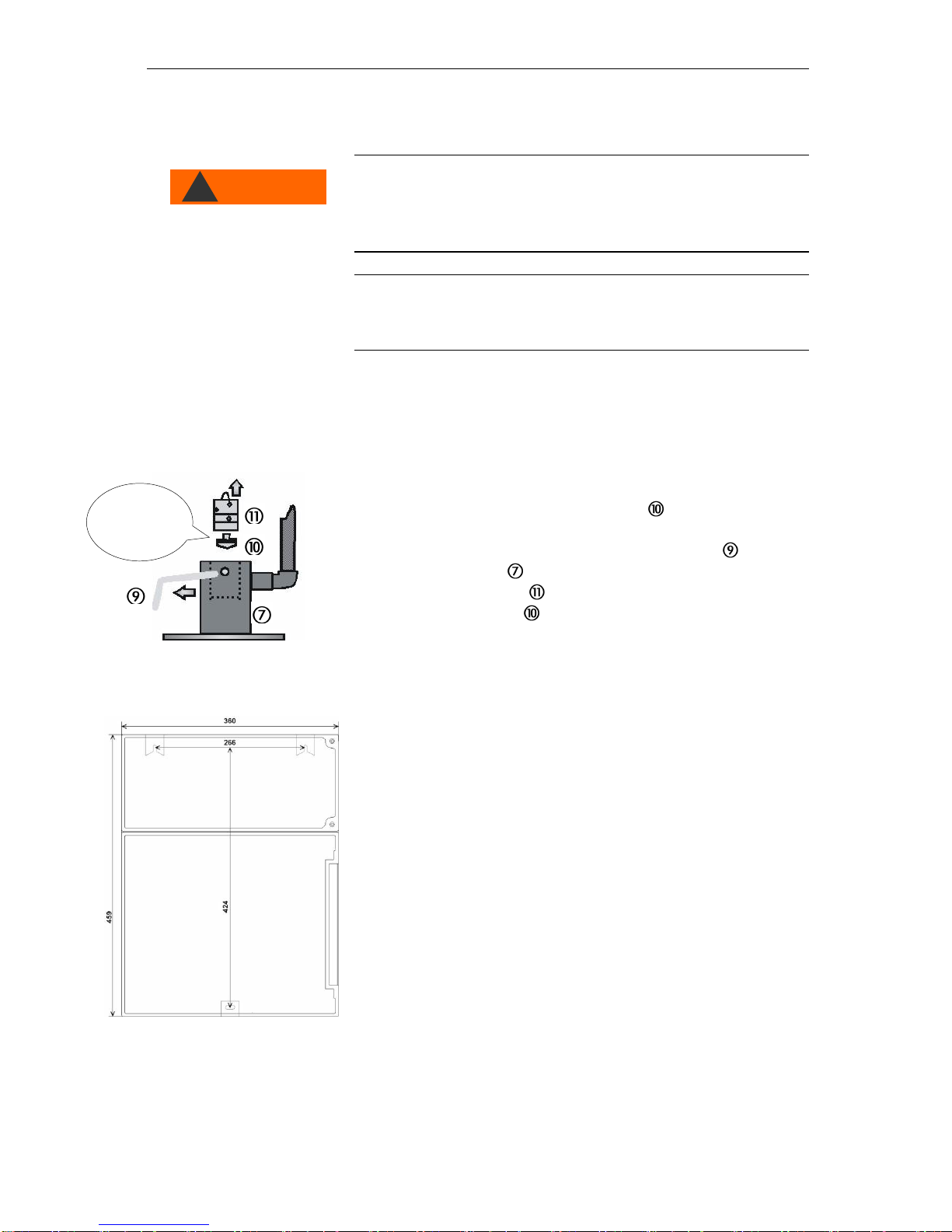
Operating Testomat 2000®V in the pressure
range of 0.3 to 1 bar
Prior to installation, please check whether lower operating pressure is
required. The instrument is factory set for the operating range of 1 to
8 bar. Remove the flow controller valve body to operate the
instrument in the operating range of 0.3 to 1 bar (e.g. when using an
aerator type R). This involves removing the retaining pin from the
controller/filter receiver . Subsequently use the metal bracket to
remove the controller plug from the borehole. Then remove the
flow controller valve body and reinsert the controller plug and the
retaining pin.
Installing Testomat 2000®
Select an installation site where the water inlet hose can be kept as
short as possible (max. 5 m).
Please leave sufficient space on the left-hand side of the
instrument to open the door.
Drill the mounting holes as shown in the drawing on the left.
Use three screws to attach the instrument at a suitable position in
the switch cabinet or on a wall.
NOTE
WARNING
!
Remove for
pressure range
0.3 to 1 bar

Installation
13
Connecting the water inlet and outlet
Information for trouble-free operation
The water pressure must be between 0.3 bar and 8 bar
Avoid strong pressure fluctuations
The measuring water temperature must be between 10 °C and
40 °C
For temperatures above 40 °C, a cooler should be installed in the
branch line of Testomat 2000®.
Mains water supply
–The branch line should be positioned at minimum 1m and
maximum 5m behind the mixing valve. This is necessary for
completely mixed sample water.
–The branch line to Testomat7 with a hand-operated shut-off valve
must be kept not longer than a maximum of 5 meters to prevent
long regulation times.
It is important that the branch line connection is taken vertically from
the top of the main soft water line in order to prevent dirt particles
from entering into the measuring chamber.
NOTE
Installation
14
Water inlet
The measuring water is taken from the main water line of the water
treatment plant and fed to the inlet connection of Testomat 2000®.
The instrument is equipped with a plug connector for plastic hoses
6/4 x 1 (external diameter 6 mm/ internal diameter 4 mm, wall
thickness 1 mm) as standard.
Install the connection for the branch line of Testomat 2000® V
directly at the main water line directly after the water treatment
plant
It is important that the branch line connection is laid vertically
upwards in order to prevent dirt particles from entering the
instrument from the main water line
.
Install a manually operated shut-off valve in the branch to
Testomat 2000®V.
Use an opaque plastic hose 6/4 x 1 (max. length 5 m) for the water
inlet .
Flush the inlet to remove any dirt particles.
When operating within a pressure range of 0.3 to 1 bar or with a
supply via a booster pump, please remove the valve body from the
controller and the filter housing. The pump should have a feeding
capacity of between 25 and 35 litres/hour and be resistant to the
medium being measured.
When using a cooler
The hot water can cause burns and damage wetted parts of
Testomat 2000® V.
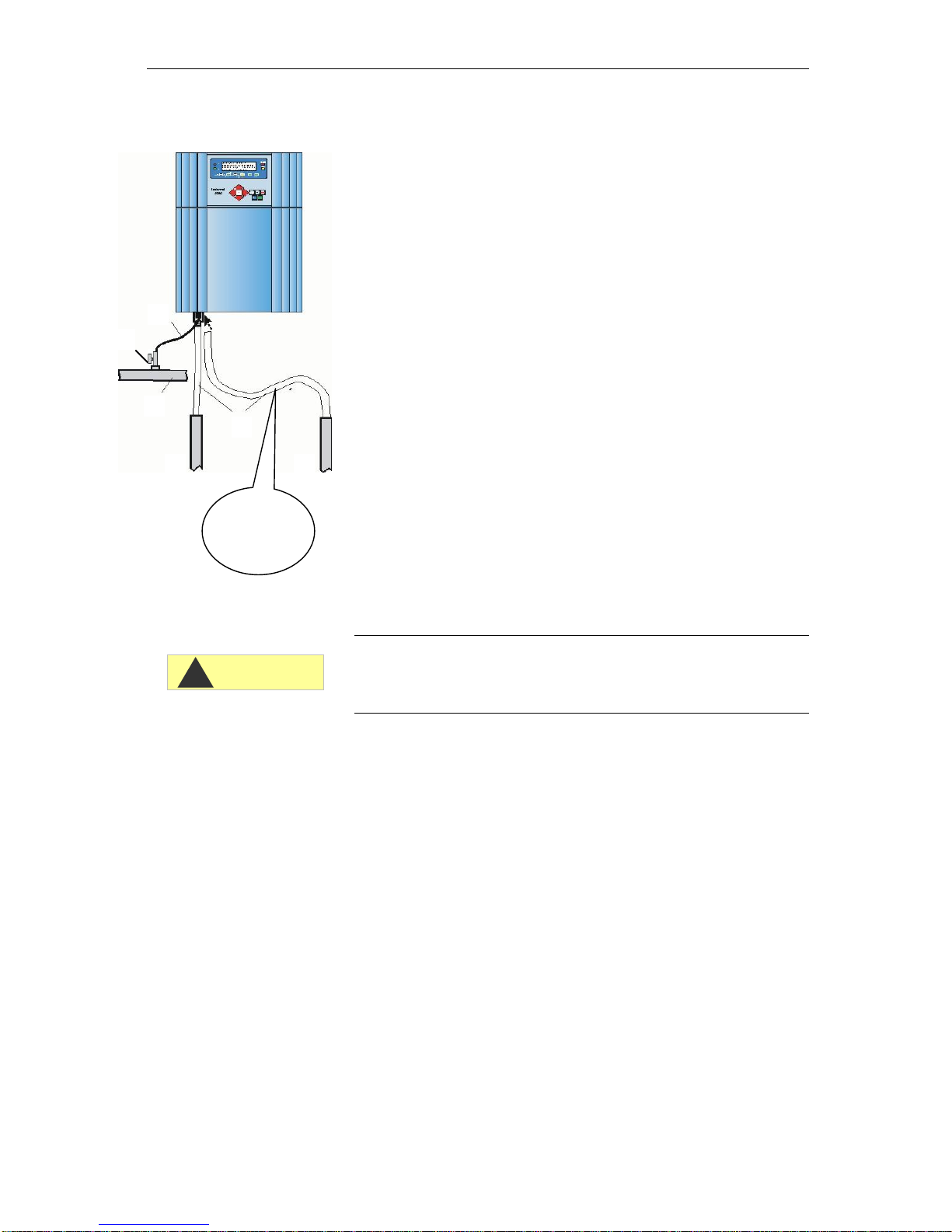
Water outlet
The feed water flows through the measuring chamber to the drain via
the outlet hose.
Connect the outlet connection of Testomat 2000®V to an opaque
outlet hose(internal diameter 12 mm).
Lay this hose without backwater development and any syphoning
effect, e.g. via an open funnel, to the drain.
NO !!
"Sagging"
causes
backwater!
CAUTION
!
Installation
15
Connecting the power supply and devices
Risk of electric shocks during installation!
If the power supply is not disconnected prior to installation, it may
result in personal injuries, destruction of the product or damage to
plant parts.
Always disconnect the relevant plant parts before installing
Testomat 2000® V.
Only use tested cables with sufficient cross-sections for the
connections.
Risk of damages caused by electromagnetic fields!
If Testomat 2000®V or the connecting cables are installed parallel
to power cables or in close proximity to electromagnetic fields, the
instrument may be damaged or measurements incorrect.
Ensure that connecting cables are as short as possible.
Always install connecting cables and power cables separately.
Connect the instrument to the protective earth conductor (for
230/115 VAC).
Protect Testomat 2000® V against interference voltages –e.g. by
using a mains filter.
Shield the instrument against strong electromagnetic fields.
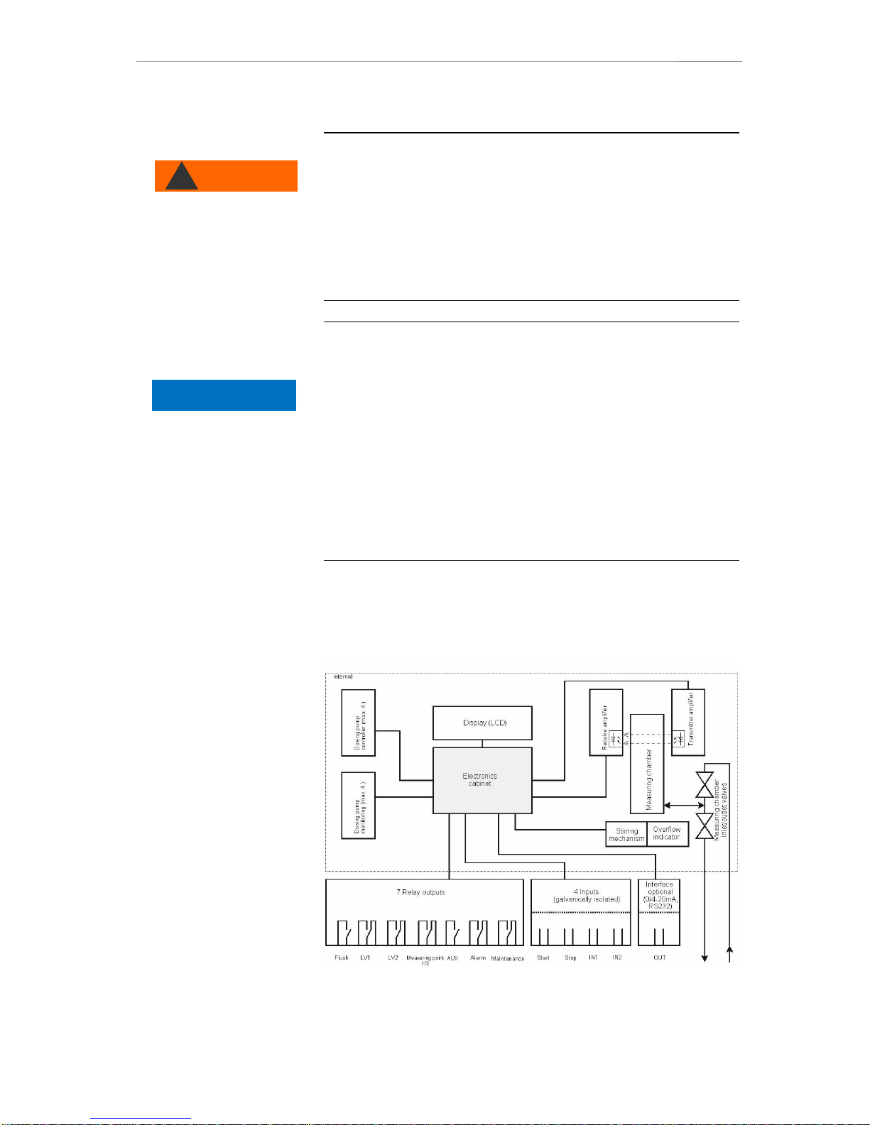
Block diagram Testomat 2000® V
Drawn relay positions: Instrument de-energised
WARNING
!
HINWEIS
Installation
16
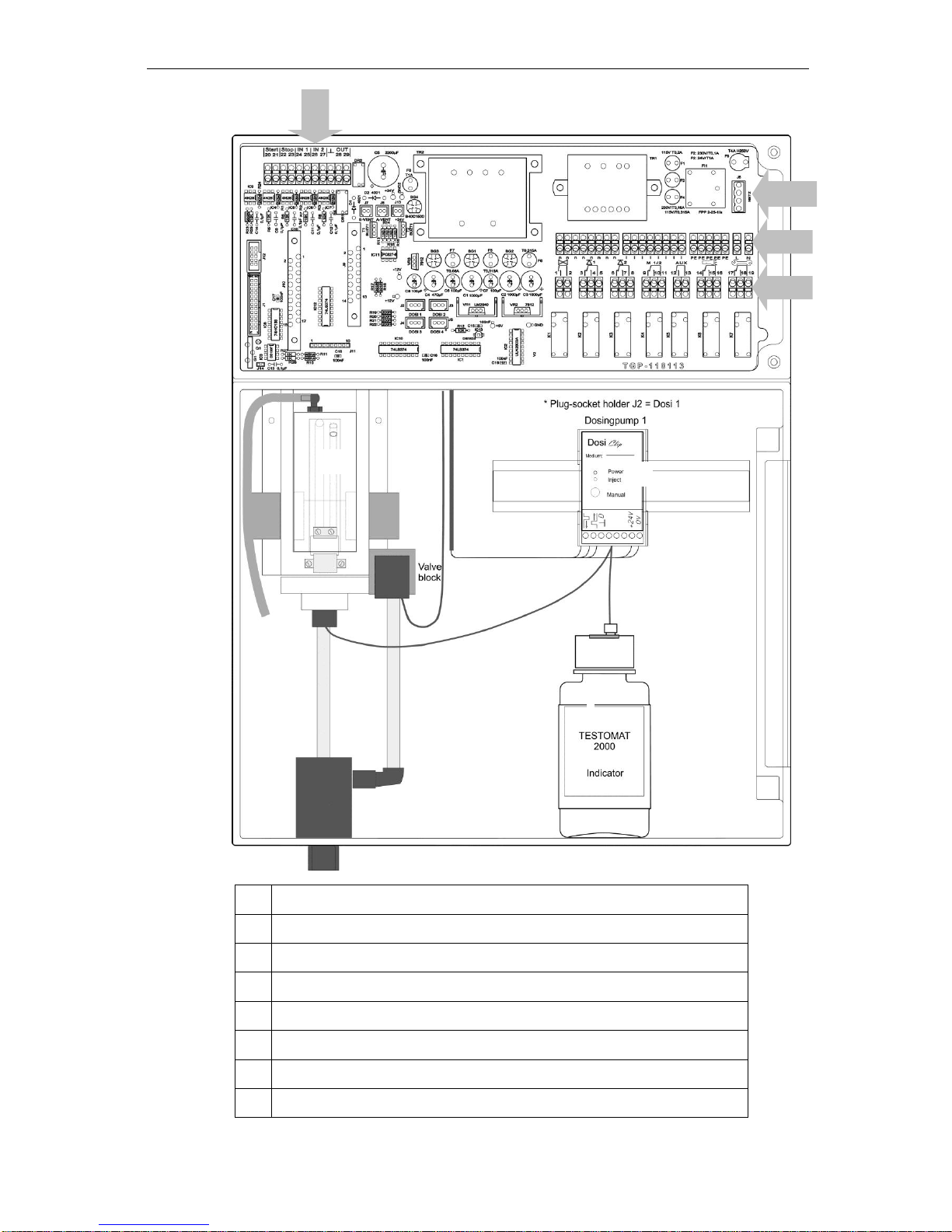
Internal design Testomat 2000® V
Terminal strip for inputs Start, Stop, IN1, IN2, and output OUT
Mains switch
Terminal strip for power input and power output
Terminal strip for relay outputs
Dosing pump
Water connections, inlet and outlet
Controller / Filter receiver
Measuring chamber
Installation
17
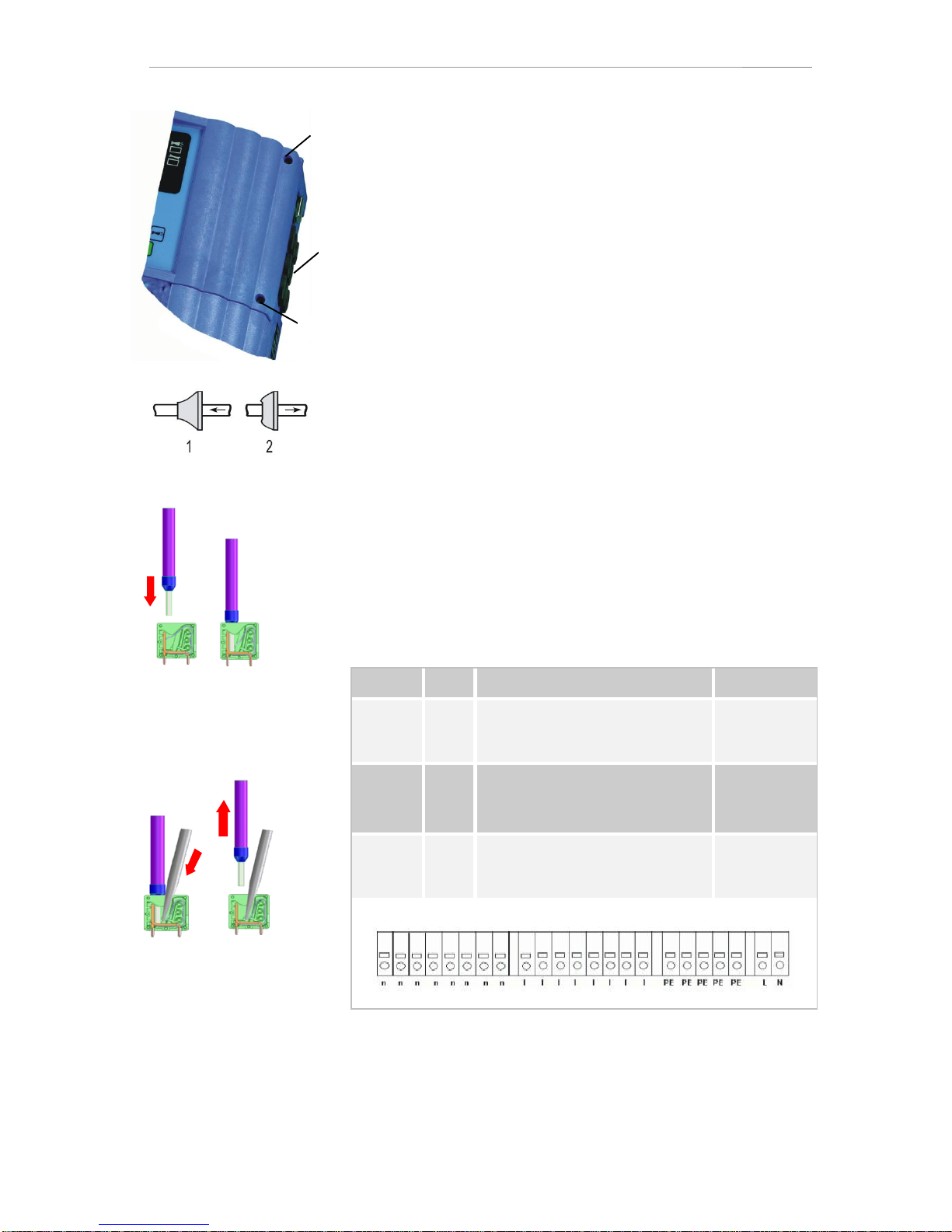
Connecting the mains voltage
Only connect the instrument to the specified mains voltage. Refer to
the rating plate for the appropriate mains voltage. Connect the cables
as follows:
Loosen both fastening screws and open the upper door. The
terminal box is now accessible.
Pierce the required rubber cable glands with a screwdriver and
insert the cable through the bush into the terminal box (1)
Subsequently pull back the cable until the bush has been turned
over (2).
Connect the power supply to terminals PE, N, L or for 24 V
instruments to terminals U, V.
Connect the conductor to the terminal block as shown on the left
.
Ensure that the leads are held securely in the terminals.
Proceed as shown in figure to loosen the connection.
Terminal
Type
Function
Comment
PE
IN
Protective earth conductor (5x)
Only for
mains
115/230 V !
N (U)
L (V)
IN
Mains, N= neutral conductor (U=24 V)
Mains, L= phase (V=24 V)
Mains input
24 V / 115 V /
230 V
n
l
OUT
Neutral, switched (8x)
Phase, switched (8x)
Mains for
consumers,
max. 4 A
Insert the conductor with
ferrule or the solid conductor
into the round input.
1. Insert a screwdriver
into the square opening
without force in order
to open the terminal.
2. Once the terminal has been
opened, remove the conductor.
Installation
18
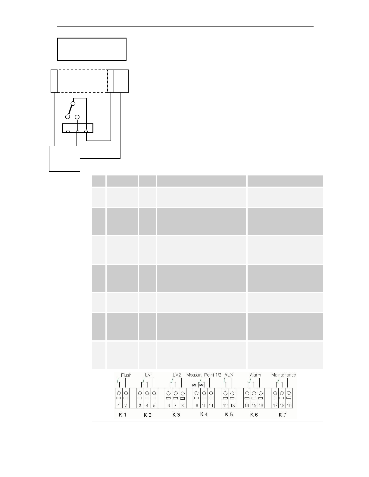
Connecting the plant components
Connect the plant components to the output terminals of relays 1
to 19 (e.g. valves).
If the plant components require mains voltage, connect the
switched mains voltage (l) to the common contact of the
respective relay (see the connection example for 230 VAC on the
left).
Connect the neutral conductor of the plant component to one of the
terminals (n).
For components with a protective earth conductor connection,
connect it to the PE connection.
Ensure that the leads are held securely in the terminals.
(Drawn relay positions: Instrument de-energised)
No.
Terminal
Type
Function
Comment
1
2
Flush
OUT
External flush valve
Isolated relay output, max.
240 VAC, 4 A
3
4
5
LV1
OUT
Limit value output 1 –N/C
Limit value output 1 –N/O
Limit value output 1 - Common
Isolated relay output, max,
max. 240 VAC, 4 A
6
7
8
LV2
OUT
Limit value output 2 –N/C
Limit value output 2 –N/O
Limit value output 2 - Common
Isolated relay output, max.
240 VAC, 4 A
9
10
11
M. point.
1/2
OUT
Measuring point 1 –N/C
Measuring point 2 –N/O
M. point switch-over - Common
Isolated relay output, max.
240 VAC, 4 A
12
13
AUX
OUT
Universal output
Isolated relay output, max.
240 VAC, 4 A
14
15
16
Alarm
OUT
Fault message output –N/C
Fault message output –N/O
Fault message output - Common
Isolated relay output, max.
240 VAC, 4 A
17
18
19
Maintenan
ce
OUT
Maintenance message –N/C
Maintenance message –N/O
Maintenance message - Common
Isolated relay output, max.
240 VAC, 4 A
Connection example
Limit value contact LV 1
switches mains voltage
n
l
3
4
5
e.g.
solenoid
valve
PE

Installation
19
Connecting the inputs and outputs
Testomat 2000® V has the following connections for control and
monitoring functions.
Do not connect an external voltage to these connections!
Ensure that the leads are held securely in the terminals.
Use the two fastening screws to close the upper door once
installation has been completed.
For more information, please refer to the section entitled "Description
of the signal inputs/outputs".
No.
Terminal
Type
Function
Comment
20
21
Start
IN
External analysis start
common earth for inputs
Only connect isolated normally
open contact!
22
23
Stop
IN
External analysis stop
common earth for inputs
Only connect isolated normally
closed/open contact!
24
25
IN1
IN
Universal input 1 (External fault
message)
common earth for inputs
Only connect isolated normally
closed/open contact!
26
27
IN2
IN
Universal input 2 (water meter)
common earth for inputs
Only connect isolated normally
open contact!
┴
28
29
OUT
OUT
Earth
0/4 - 20 mA galvanically
separated
Earth = ┴
28 = (+) or (TxD)
29 = (-) or (RxD)

Commissioning
20
Commissioning
Handling of reagents/indicators
Adhere to the respective safety data sheet!
Trouble-free operation of Testomat 2000®V is only guaranteed
when using Heyl Testomat 2000®
V
indicators!
Inserting the indicator bottle
Open the lower housing door by pulling on the right-hand side.
Remove the cap from the indicator bottle.
Remove the plastic bag from inside the lower housing door. The
plastic bag contains the screw cap with hole and the insert
for the screw cap.
Connect the parts as shown on the left.
Screw the hose connector of the intake hose hand-tight into
the insert .
Place the insert with the screwed-in intake hose into the indicator
bottle.
Now screw the screw cap with hole hand-tight onto the
indicator bottle.
Extracting the indicator
Switch the instrument on and press the "STANDBY" key.
During operation, the pump (DOSIClip) automatically extracts
indicator.
To ensure that indicator is available for the initial analyses, the
intake hose and the transport hose must be filled with
indicator from the pump up to the measuring chamber.
Press the "manual" key several times until the intake hose
and the transport hose are filled with indicator up to the
measuring chamber (always switch on the instrument at the mains
switch first!)
If necessary, manually tighten the hose connectors of the intake
and transport hose slightly in case of bubble formation.
Opening the water inlet
Open the lower housing cover.
Slowly open the manually operated shut-off valve to prevent the
measuring chamber overflowing. The flow regulator requires a few
seconds to function correctly.
Make sure that the water conducting parts are not leaky.
CAUTION
!
Indicator
Table of contents
Other Heyl Neomeris Controllers manuals


