HF rotoss-PW11 User manual

Protoss-PW11 User Manual
http://www.iotworkshop.com - 1 -
Protoss-PW11
RS485 to Wi-Fi
User Manual
V 1.1
Overview of Characteristic
Support 802.11bgn Wireless Standard
Support STA/AP/AP+STA Mode
Support SmartLink V8 Smart Config (Provide APP)
Support TCP/UDP/MQTT/HTTP/WebSocket Protocol
Support Modbus TCP to RTU, Modbus Master Function
Support RS485 To WiFi Conversion
Support Webpage Easy Configuration or PC IOTService Tool
Support Security Protocol Such As TLS/AES/DES3

Protoss-PW11 User Manual
http://www.iotworkshop.com - 2 -
Support Heartbeat and Resister Packet Function
Support Webpage OTA Wireless Upgrade
Support Industrial Temperature: -40 to +85˚ C
Multiple Type of Different Power Input:
◼Protoss-PW11-H:100~240VAC@50~60Hz
◼Protoss-PW11-M:9~48VDC@1A
Size: 102.03 x 64.95 x 27.50 mm (L x W x H) ,C45 rail installation

Protoss-PW11 User Manual
http://www.iotworkshop.com - 3 -
TABLE OF CONTENTS TABLE OF CONTENTS
TABLE OF CONTENTS TABLE OF CONTENTS...........................................................................3
LIST OF FIGURES............................................................................................................................4
LIST OF TABLES .............................................................................................................................5
HISTORY...........................................................................................................................................5
1. PRODUCT OVERVIEW........................................................................................................6
1.1. General Description.........................................................................................................6
1.2. Device Paremeters...........................................................................................................6
1.3. Key Application................................................................................................................7
2. HARDWARE INTRODUCTION...........................................................................................8
2.1. Interface Definition ..........................................................................................................9
2.2. RS485 Interface..............................................................................................................10
2.3. Mechanical Size .............................................................................................................11
2.4. Product Installation .......................................................................................................13
2.5. Order Information ..........................................................................................................13
3. NETWORK STRUCTURE..................................................................................................14
3.1. Wireless Network...........................................................................................................14
3.1.1. AP Network .....................................................................................................................14
3.1.2. STA Wireless Network ....................................................................................................15
3.1.3. AP+STA Wireless Network .............................................................................................15
3.1.4. IOTService Software.......................................................................................................17
3.1.5. Webpage Configuration...................................................................................................17
4. FUNCTION DESCRIPTION...............................................................................................19
APPENDIX A: CONTACT INFORMATION ...............................................................................20

Protoss-PW11 User Manual
http://www.iotworkshop.com - 4 -
LIST OF FIGURES
Figure 1. Protoss-PW11 Appearance .............................................................................................................8
Figure 2. Protoss-PW11 Interface...................................................................................................................9
Figure 3. Protoss-PW11 Mechanical Dimension...........................................................................................12
Figure 4. C45 Rail Installation.......................................................................................................................13
Figure 5. Protoss-PW11 Product Order Information .....................................................................................13
Figure 6. General AP Network......................................................................................................................14
Figure 7. STA Application.............................................................................................................................15
Figure 8. AP+STA Wireless Network............................................................................................................16
Figure 9. Config Wi-Fi Parameter.................................................................................................................17
Figure 10. STA Scan Parameter.....................................................................................................................17
Figure 11. Configure the Wi-Fi Parameter......................................................................................................18
Figure 12. STA Scan.......................................................................................................................................18

Protoss-PW11 User Manual
http://www.hi-flying.com - 5 -
LIST OF TABLES
Table1. Protoss-PW11 Technical Specifications.................................................................................................6
Table2. Protoss-PW11-H Interface Definition......................................................................................................9
Table3. Protoss-PW11-M Interface Definition ...................................................................................................10
HISTORY
Ed. V1.0 02-10-2020 First Version
Ed. V1.1 03-18-2020 Update RS485 interface

Protoss-PW11 User Manual
http://www.hi-flying.com - 6 -
1.PRODUCT OVERVIEW
1.1. General Description
The Protoss-PW11 provides a RS485 interface to TCP/IP data transfer product. The Protoss-PW11
integrate TCP/IP controller, memory, Wi-Fi transceiver, RS485 and integrates a fully developed
TCP/IP network stack. Protoss-PW11 also includes an embedded web server used to configure
device.
The Protoss-PW11 using highly integrated hardware and software platform, it has been optimized for
all kinds of applications in the industrial control, smart grid, personal medical application and remote
control that have lower data rates, and transmit or receive data on an infrequent basis.
1.2. Device Paremeters
Table1. Protoss-PW11 Technical Specifications
Item
Parameters
System Information
Processor/Frequency
160MHz
Flash/SDRAM
2MB/352KB
Operating System
mbed
Network Protocol
Network Protocol
IP,TCP,UDP,DHCP,DNS,HTTP Server/Client,ARP,
BOOTP, AutoIP, ICMP,Web socket, Telnet, uPNP, NTP,
Modbus TCP
Security Protocol
TLS v1.2
AES 128Bit
DES3
Wi-Fi Interface
Standard
802.11 b/g/n
Frequency
2.412GHz-2.484GHz
Network Mode
STA/AP/STA+AP
Security
WEP/WPAPSK/WPA2PSK
Encryption
WEP64/WEP128/TKIP/ AES
Tx Power
802.11b: +18dBm (Max.)
802.11g: +16dBm (Max.)
802.11n: +15dBm (Max.)
Rx Sensitive
802.11b: -89dBm
802.11g: -81dBm
802.11n: -71dBm
Antenna
SMA Interface Antenna
Serial Port
Port Number
RS485
Data Bits
7,8

Protoss-PW11 User Manual
http://www.hi-flying.com - 7 -
Stop Bit
1,2
Check Bit
None, Even, Odd
Baud Rate
TTL: 300 bps~230400 bps
Flow Control
No Flow Control
Software Xon/ Xoff flow control
Software
Web Pages
Http Web Configuration
Customization of HTTP Web Pages
Configuration
Web
CLI
XML import
Telnet
IOTService PC Software
Basic Parameter
Size
102.03 x 64.95 x 27.50 mm
Operating Temp.
-40 ~ 85°C
Storage Temp.
-45 ~ 105°C, 5 ~ 95% RH(no condensation)
Input Voltage
Protoss-PW11-H:100~240VAC@50~60Hz
Protoss-PW11-M:9~48VDC@1A
Working Current
~200mA
Power
<700mW
1.3. Key Application
The Protoss-PW11 device connects serial device to Ethernet networks using the TCP/IP protocol:
⚫Remote equipment monitoring
⚫Asset tracking and telemetry
⚫Security Application
⚫Industrial sensors and controls
⚫Medical devices
⚫ATM machines
⚫Data collection devices
⚫Universal Power Supply (UPS) management units
⚫Telecommunications equipment
⚫Data display devices
⚫Handheld instruments
⚫Modems
⚫Time/attendance clocks and terminals

Protoss-PW11 User Manual
http://www.hi-flying.com - 8 -
2.HARDWARE INTRODUCTION
The Protoss-PW11 unit is a complete solution for serial port device connecting to network. This
powerful device supports a reliable and proven operating system stored in flash memory, an
embedded web server, a full TCP/IP protocol stack, and standards-based (AES) encryption.
Through Ethernet cable connect router with Protoss-PW11 serial server for data transfer, which makes
the data transformation very simple.
Figure 1. Protoss-PW11 Appearance

Protoss-PW11 User Manual
http://www.hi-flying.com - 9 -
2.1. Interface Definition
Figure 2. Protoss-PW11 Interface
Table2.Protoss-PW11-H Interface Definition
Pin
Description
Net Name
Signal
Type
Comment
1
AC Power Input
L
Power
100~240VAC Input
2
AC Power Input
N
Power
5
RS485_B-
IO
RS485 B-
6
Signal GND
GND
Power
Used for RS485 GND, usually leave it
unconnected
7
RS485_A+
IO
RS485 A+
ANT
Antenna
ANT
Wi-Fi 2.4G SMA Antenna
Reload
Restore to factory
setting button
Reload
I
Detailed functions see <Notes>
Reset
Reset button
Reset
I
Hardware reset button
Net
Network status LED
Net
O
Boot On: Boot OK.
0.1s Off -> 0.1s On: SmartLink Config Mode
0.3s Off -> 3s On: STA mode connect to router
or AP mode being connected by other STA.
0.3s Off ->0.3s On: No Wi-Fi Connection
Active
UART Data
Transfer
Active
O
Off: No data transfer
0.3s Off -> 0.9s On: UART TX Output
0.3s Off -> 0.3s On: UART RX Receive
On: UART bidirection.
Power
Power LED
Power
O
On: Power input OK
Off: Power input NG.
Link
Server connection
LED
Link
O
On: netp Socket connection OK.
Off: no netp Socket connection.

Protoss-PW11 User Manual
http://www.hi-flying.com - 10 -
Table3.Protoss-PW11-M Interface Definition
Pin
Description
Net Name
Signal Type
Comment
1
DC Power Input
VCC+
Power
9~48VDC@1A Input
2
DC Power Input
GND-
Power
5
RS485_B-
IO
RS485 B-
6
Signal GND
GND
Power
Used for RS485 GND, usually leave it
unconnected
7
RS485_A+
IO
RS485 A+
ANT
Antenna
ANT
Wi-Fi 2.4G SMA Antenna
Reload
Restore to factory
setting button
Reload
I
Detailed functions see <Notes>
Reset
Reset button
Reset
I
Hardware reset button
Net
Network status
LED
Net
O
Boot On: Boot OK.
0.1s Off -> 0.1s On: SmartLink Config Mode
0.3s Off -> 3s On: STA mode connect to
router or AP mode being connected by other
STA.
0.3s Off ->0.3s On: No Wi-Fi Connection
Active
UART Data
Transfer
Active
O
Off: No data transfer
0.3s Off -> 0.9s On: UART TX Output
0.3s Off -> 0.3s On: UART RX Receive
On: UART bidirection.
Power
Power LED
Power
O
On: Power input OK
Off: Power input NG.
Link
Server
connection LED
Link
O
On: netp Socket connection OK.
Off: no netp Socket connection.
<Notes>
I —Input; O —Output; I/O: Digital I/O; Power—Power Supply
nReload Pin (Button) function:
1. After module is powered up, short press this button (0.2< “Low” <1.5s) and loose to
make the module go into “SmartLink“config mode, waiting for APP to set password
and other information. Download SmartLink V8 APP as following link:
http://www.hi-flying.com/download-center-1/applications-1/download-item-smartlink-v8
2. After module is powered up, long press this button (“Low” > 4s) and loose to make
the module recover to factory setting.
2.2. RS485 Interface
RS485 use two wire links, A(DATA+), B(DATA-). Connect A(+) to A(+), B(-) to B(-) for communication.
Suggest to connect GND together when interference is very severe.
The RS485 interface support maximum 32 RS485 device. The cable maximum length is 1200 meters.
Need to add 120Ohm terminal resistor for over 300 meters.


Protoss-PW11 User Manual
http://www.hi-flying.com - 14 -
3.NETWORK STRUCTURE
3.1. Wireless Network
Product can be set as a wireless STA and AP as well. And logically, it supports two wireless interfaces,
one is used as STA and the other is AP. Other STA devices can join into the wireless network through
AP interface. So it can provide flexible networking method and network topology.
AP: Wireless access point which is the central joint. Usually, wireless router is a AP, other STA
devices can connect with AP to join the network.
STA: Wireless station which is terminal of a wireless network. Such as laptop and pad etc.
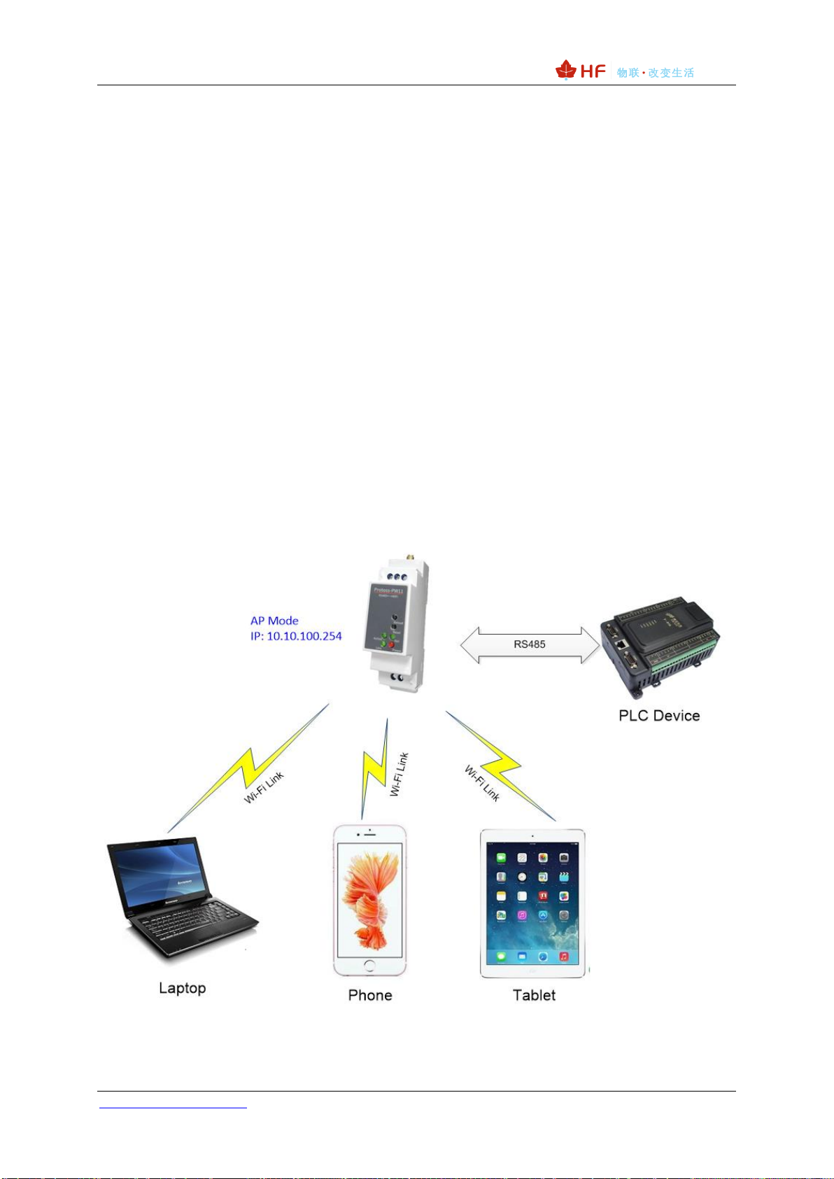
3.1.1. AP Network
All the STA devices connect to the device AP transfer data to PLC device. Note the STA devices can
not communicate to each other due to PW11 does not support router function, if need this function,
use PW21/HF2211/HF2221
Figure 6. General AP Network
Protoss-PW11 User Manual
http://www.hi-flying.com - 15 -
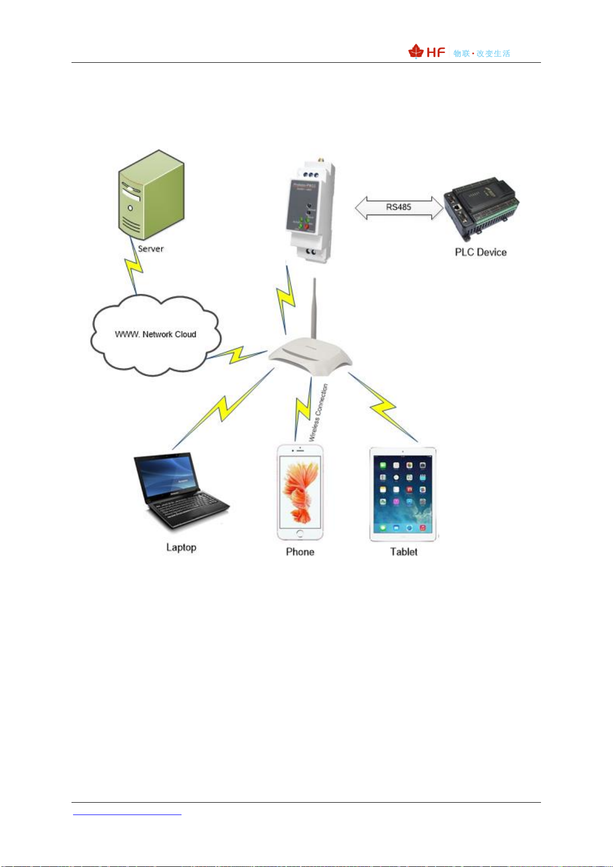
3.1.2. STA Wireless Network
Take the following picture as example. When router works in AP mode, product connects to the user’
s devices by RS485 interface. In this topology, the whole wireless network can be easily stretched.
Figure 7. STA Application
3.1.3. AP+STA Wireless Network
Product can support AP+STA method. It can support AP and STA interface at the same time.Shown
as follow:

Protoss-PW11 User Manual
http://www.hi-flying.com - 16 -
Figure 8. AP+STA Wireless Network
In this picture, open the AP+STA function and the STA interface can be connected to the remote
server by the router. Similarly, the AP interface can also be used. Phone/PAD can be connected to the
AP interface and to control the serial devices or set itself.
Through AP+STA function, it is convenient to use Phone/PAD to monitor the user’s devices and not
change its original settings.
Notes that:
When the AP+STA function is opened, the STA interface needs to connect to other router.
Otherwise, STA interface will endlessly scan the router information nearby. When it is scanning,
it will bring bad effects to the AP interface, like losing data etc.
AP and STA parts must set to the different sub-network for the product working as APSTA
mode.

Protoss-PW11 User Manual
http://www.hi-flying.com - 17 -
Does not support Wi-Fi repeater function that means device works in AP+STA(STA connects to
router), PC connects to device AP, but can not access to internet (If need this router function,
use PW21/HF2211/HF2221)
3.1.4. IOTService Software
Open the IOTService after PC connect to the AP hotspot generated by product, then config the
parameter.
Figure 9. Config Wi-Fi Parameter
Figure 10. STA Scan Parameter
3.1.5. Webpage Configuration
Use PC to connect with product’s AP. Input the default IP(10.10.100.254, default username and
password: admin/admin) to login the webpage to configure the parameter.


Protoss-PW11 User Manual
http://www.hi-flying.com - 20 -
APPENDIX A: CONTACT INFORMATION
------------------------------------------------------------------------------------------------------------
Address: Room 1002,Building 1,No.3000,Longdong Avenue,Pudong New
Area,Shanghai,China,201203
Web: www.iotworkshop.com or www.hi-flying.com
Contact:
Sales: sales@iotworkshop.com
Support: support@iotworkshop.com
Service: service@iotworkshop.com
Business: business@iotworkshop.com
---------------------------------------------------------------------------- -------------------------------
For more information about IOTworkshop modules, applications, and solutions, please visit our web
site www.iotworkshop.com
<END OF DOCUMENT>
Table of contents


