Emcotec DPSI V-Match User manual
Bedienungsanleitung

DPSI V-Match Operating Instructions Version 1.0
Page 2 of 16

DPSI V-Match Operating Instructions Version 1.0
Page 3 of 16
Contents
1. Functionality....................................................................................4
2. Programming...................................................................................6
2.1. Changing Servo Direction........................................................7
2.2. Calibrating Servo Center .........................................................8
2.3. Calibrating End-Limits..............................................................9
2.4. Deleting all Programming ......................................................10
3. Additional Hints.............................................................................11
3.1. Adapting several Servos........................................................11
3.2. Changing the Model...............................................................12
3.3. Sequence of Programming....................................................12
3.3. Limiting Tuning Range...........................................................12
4. Technical Data...............................................................................14
5. Warranty.........................................................................................15

DPSI V-Match Operating Instructions Version 1.0
Page 4 of 16
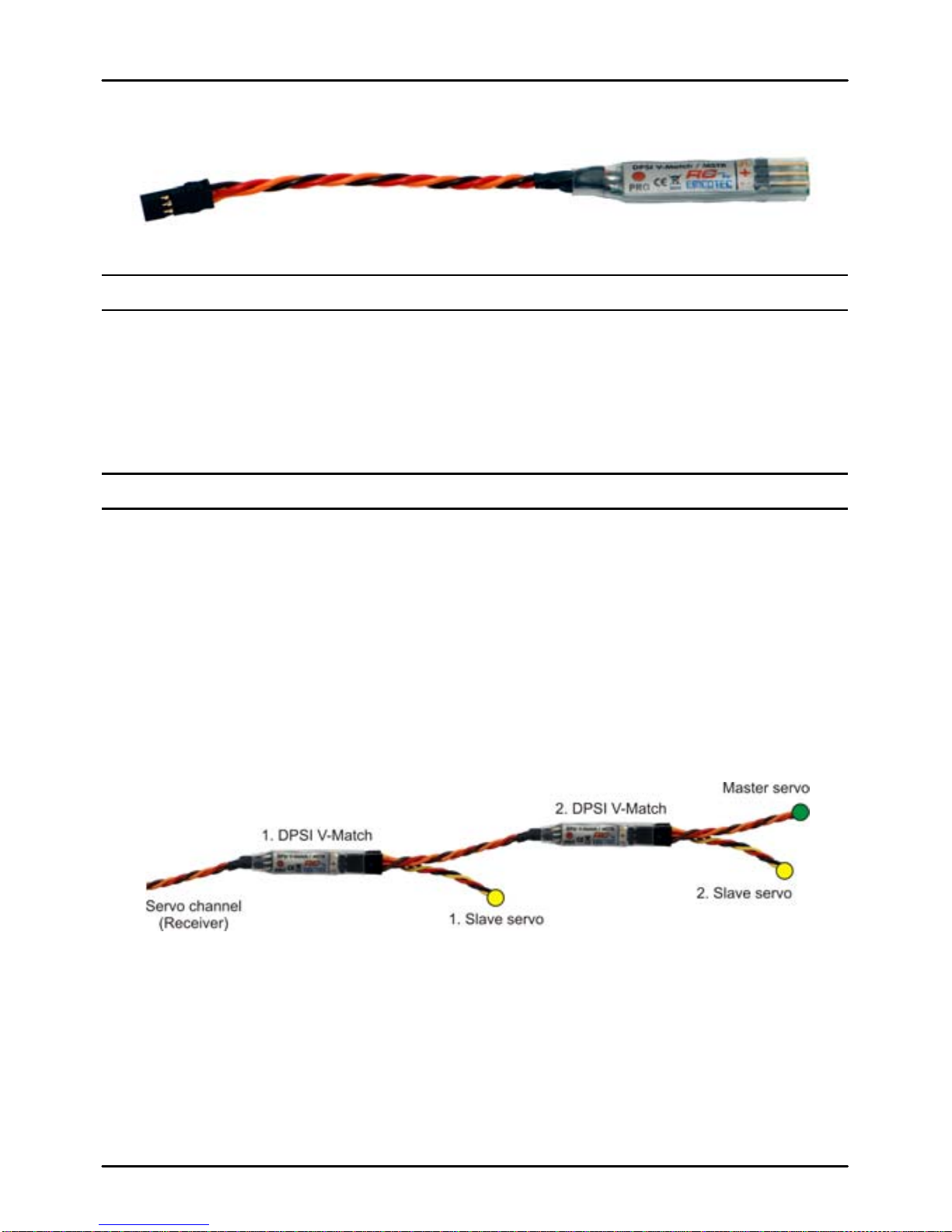
1. Functionality
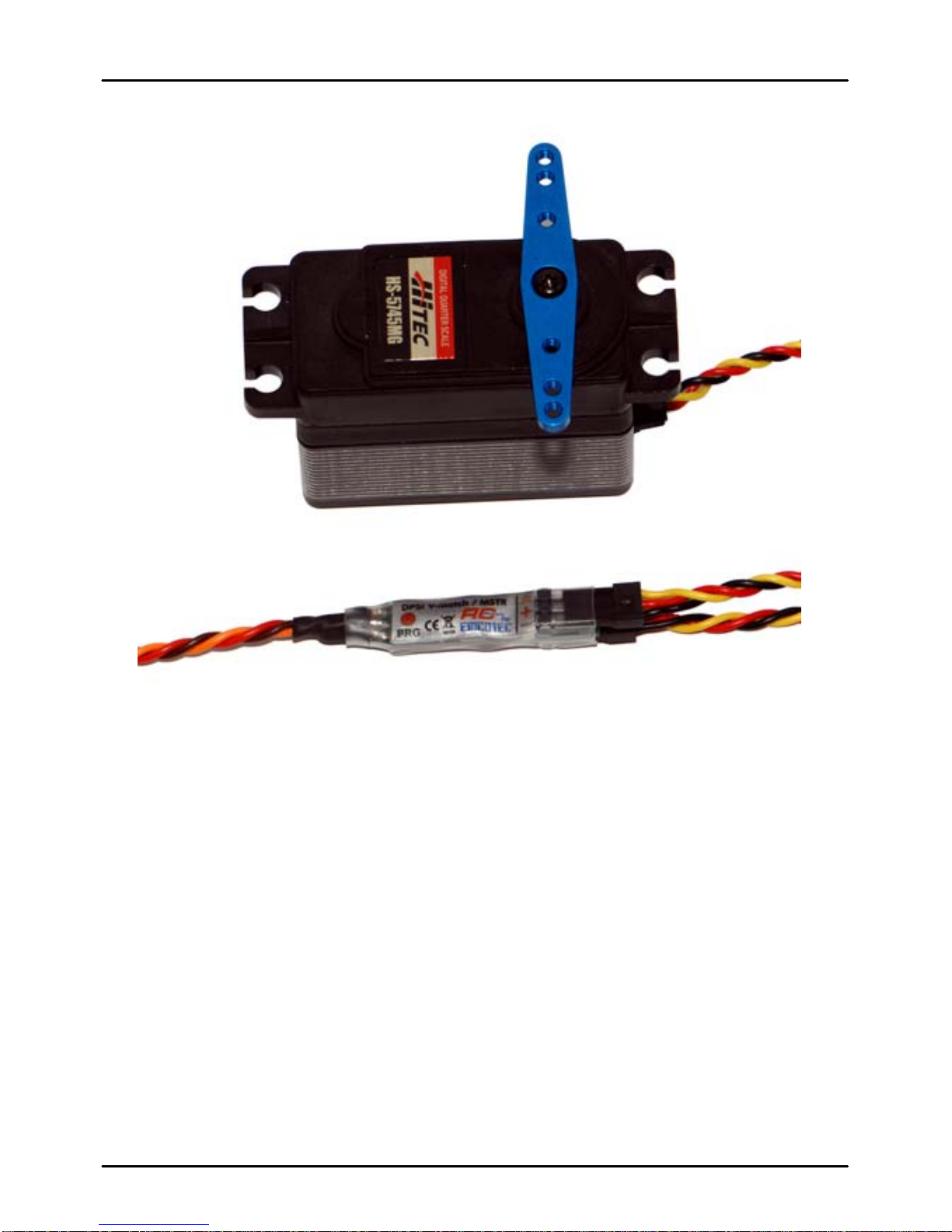
DPSI V-Match constitutes a servo V-cable
that accommodates two commercially
available servos.
As a special feature, one servo (SLAVE) is
programmable for direction, as well as
center position and end-limits. Therefore,
this servo adapts ("matches") to the main
servo (MSTR).
This is especially handy if two servos actuate on one rudder (e.g. two
servos on one aileron) and synchronism cannot be established by
mechanically means. Often, it suffices if one servo's direction can be
changed (e.g. counter rotating mounted servos for the airplane's
elevator). This too, is simply accomplished with DPSI V-Match.
Failsafe-Function:
A failsafe-function is added to its features. Both servos (MSTR and
SLAVE) remain at their current position (HOLD) when encountering an
erroneous or missing receiver signal until a valid signal is again
delivered by the receiver. A flashing red LED (at the PCB's side)
indicates this state and stays active (i.e. flashes) until power is turned
off.
Powerful Servos:
The electronically design of the DPSI V-Match allows for usage of
powerful digital servos; supply voltage ranging up to 8.4 volts. Due to
the PCB (4-layer) and the thick (0.34 mm2) connection cable, current
load is especially high.
DPSI V-Match Operating Instructions Version 1.0
Page 5 of 16
Pulse Amplifier & HF-Suppression:
Besides pulse amplifiers, which recognize and amplify even weak
servo signals, high effective noise filters are built into the DPSI V-
Match. Therefore, ferrite cores or other noise suppression measures
can be omitted.
High Precision:
Because of the intelligent software design and a highly accurate crystal
oscillator, a resolution of more than 3000 steps is obtained. Therefore,
the DPSI V-Match is also suitable for modern remote control systems
with high servo positioning precision (number of steps).

DPSI V-Match Operating Instructions Version 1.0
Page 6 of 16
2. Programming
There is no external programming device necessary, e.g. a PC or a
programming box for programming of the DPSI V-Match. Only a
delivered magnet serves for activation of the corresponding
programming functions. Everything else is conducted with the
transmitter and remote control equipment.
During programming, settings of the original servo (master = MSTR)
remain unchanged! Programming always refers to the slave servo
(SLAVE).
Hint:
Adjustment / programming of the slave servo is only possible within the first 10
seconds after power on. Afterwards, programming is inhibited for safety reasons!
Hint:
Before starting EACH programming, the corresponding transmitter stick (or
switch actuator) must be positioned in center position!
Hints:
If both servos MSTR and SLAVE actuate a common rudder, at least one
servo linkage must be released in order to avoid mechanical touch.
Hint:
Whenever a change e.g. of the servo center position takes place, the end-limits
should be reprogrammed as well!
Hint:
Basic adjustments in DPSI V-Match correspond to Graupner/JR equipment.
Center position is 1.50ms; end-limits are set to 100% each. Of course, all remote
control sets can be used with no limitation.
DPSI V-Match Operating Instructions Version 1.0
Page 7 of 16
Hint:
Whenever programming takes place, the integrated red LED blinks for controlling
purposes at a rate of 0.5Hz (1s on, 1s off) at the DPSI V-Match's side.
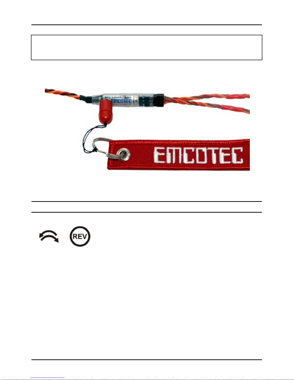
2.1. Changing Servo Direction
When changing the direction of the servo, all
other settings remain! For reversing direction of
the servo, hold the magnet close to position
"PRG" (red dot on sticker) within the first 10
seconds after power on. Distance of the magnet can be up to 8mm.
The magnet also operates through thin fuselage sidewalls, if the DPSI
V-Match is attached to the fuselage's inner sidewall using e.g. dual
adhesive tape.
2.5 seconds after positioning the magnet, the servo makes a short
move (10% stroke). If the magnet is removed within the next 5
seconds, the servo direction is reversed and permanently stored. The
DPSI V-Match now executes a restart.
DPSI V-Match Operating Instructions Version 1.0
Page 8 of 16
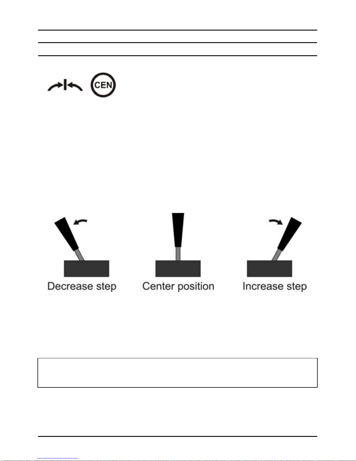
2.2. Calibrating Servo Center
Programming also starts by positioning the
magnet close to the red dot ("PRG"). The
slave servo makes a short move after 2.5
seconds (just like for servo reverse). The
magnet now is not removed, but rather remains at the "PRG" position.
The stick or switch actuator must not be moved now, i.e. it must remain
in center position. After 5 seconds, the servo makes a short move
again. Now, programming of servo center is active.
The master servo now remains centered and does not move anymore,
even if the stick is moved. With each movement of the transmitter stick
out of center, the servo position (servo center) is incremented or
decremented by one step.
If the stick remains in one end-position, steps automatically increment
or decrement after 2.5 seconds. This serves for quicker settings of the
values.
Hint:
Due to the high resolution of the DPSI V-Match, changes of the servo position
are possibly recognizable only after several steps.

DPSI V-Match Operating Instructions Version 1.0
Page 9 of 16
Remove the magnet from its red dot position ("PRG") as soon as the
slave servo reaches the desired center position. The DPSI V-Match
now starts with the newly programmed center position of the slave
servo.
Hint:
Reprogram the end-limits in order to obtain linear curves after programming the
servo center.
2.3. Calibrating End-Limits
Start programming of end-limits just like
programming servo center. Here, the
transmitter stick (or switch actuator) is set to
maximum position (servo end-limit) within 5
seconds after the servo makes its first short move. After these 5
seconds the servo moves again shortly and both servos remain in their
actual (maximum)-position. Reposition the stick to its center position –
servo positions do not alter!

DPSI V-Match Operating Instructions Version 1.0
Page 10 of 16
Here too, the stroke of the slave servo changes by increasing or
decreasing steps when moving the stick out of its center position.
Remove the magnet when the desired end position is reached.
Hint:
Whenever changing servo settings, all values should be reprogrammed, i.e.
center and end-limits! Sequence of programming (center, end-limits) does not
really matter.
Attention:
Programmable values for end-limits could possibly be higher than the mechanical
resolution of the servo. The servo therefore could be damaged or function
incorrectly (e.g. wheel spinning) when utilizing the full range. Therefore,
approximate the limiting values carefully. An additionally connected servo tester
(e.g. using the EMCOTEC Mini Servo Tester – part number A71050) can help if
in doubt, indicating the corresponding servo position digitally.
2.4. Deleting all Programming
Total reset of all programmed settings is
possible too. Position the magnet after power
on close to the "PRG" position and hold it
there for approx. 40 seconds. After 2.5
seconds and after additional 5 seconds the servo makes its short move
(just like when programming center/end-limits). The transmitter stick
must not be moved at that time and the magnet must remain at the
"PRG" position. After 40 seconds have elapsed, all settings are deleted
and a restart of the DPSI V-Match takes place. Now, the magnet can
be removed.
Hint:
Whenever programming takes place, the integrated red LED blinks for controlling
purposes at a rate of 0.5Hz (1s on, 1s off) at the DPSI V-Match's side.
DPSI V-Match Operating Instructions Version 1.0
Page 11 of 16
3. Additional Hints
These additional hints are valuable for the ambitious user who likes to
know more about the functions of the DPSI V-Match by explaining its
behavior under certain circumstances.
3.1. Adapting several Servos
If more than two servos need to be synchronized (e.g. three aileron
servos) two DPSI V-Match can be chained one after another. This
means: the input of the second DPSI V-Match connects to the MSTR
output of the first DPSI V-Match.
Now, a SLAVE output is available at the first DPSI V-Match, a MSTR
and a SLAVE output at the second one. Both SLAVE servos can now
be independently set up.

DPSI V-Match Operating Instructions Version 1.0
Page 12 of 16
3.2. Changing the Model
If a programmed DPSI V-Match is to be used in an other application
(e.g. changing a model), generally all settings should be deleted (see
also "Deleting all Programming"). This is also true if a servo with a
different rotating direction is to be built in.
3.3. Sequence of Programming
When programming the slave servo, the rotating direction (if
necessary) should always be programmed first. Then center position
and end-limits follow, sequence is unimportant.
Hint:
Whenever there is a change, e.g. serve center position, the end-limits should be
programmed, too!
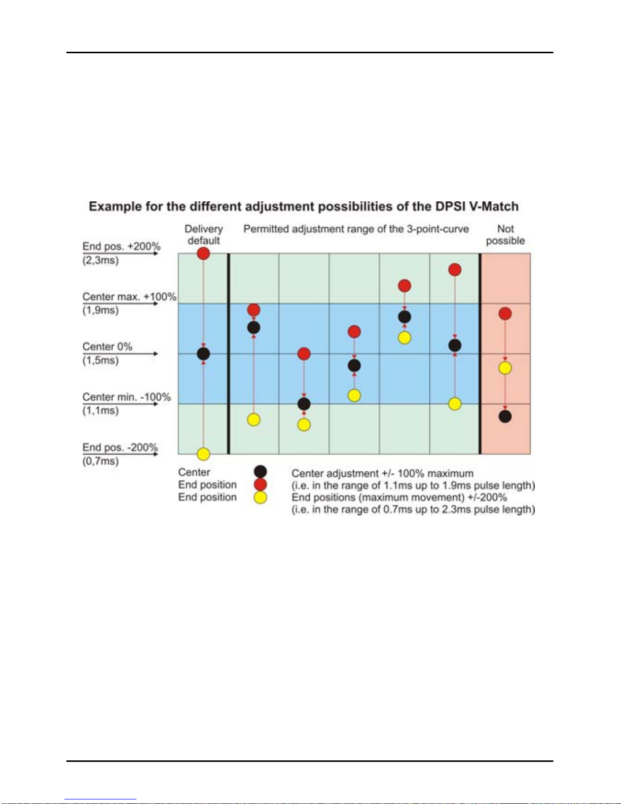
3.3. Limiting Tuning Range
The DPSI V-Match only allows for certain values when programming
or adjusting the slave servo. Because the slave servo is to be adapted
to the master servo, both servos should have similar base adjustments
in the first place, e.g. comparable center positions.
If the center of the master servo already is over 100% of the possible
servo stroke it does not make much sense to adjust the slave servo
even further. Therefore, only a maximum of +/-100% (referring to JR
values) of the servo center position is possible.
Adjustment of the slave servo is carried out by a so-called 3-point
curve (i.e. center, maximum value left/top, maximum value
right/bottom).
DPSI V-Match Operating Instructions Version 1.0
Page 13 of 16
The "distance" of the maximum position of a servo in respect to its
center must be at least 20%, otherwise the value is not programmable.
Range checking accompanies each programming. It is therefore not
possible to position the servo center position off limits. Malfunctions are
avoided this way (e.g. V-curve of the servo).
DPSI V-Match Operating Instructions Version 1.0
Page 14 of 16
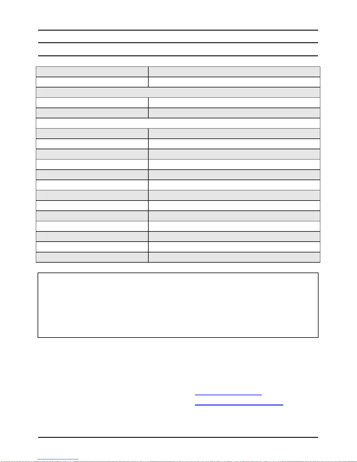
4. Technical Data
Operating Voltage Range 4V .... 8.4V
Current Consumption Approx. 4.7mA
Servo Signal Level Input:
Low-Level 0V ... 0.8V
High-Level 2.0V ... 8.4V
Servo Signal Level Output:
Supplying > 5.1V Approx. 5.0V
Supplying < 5.1V Supply voltage -0,1V
Maximum Allowable Current 8A continuous, 20A peak
Allowable Center Position +/-100% (1.10ms .... 1.90ms)
Allowable End-Limits* +/-200% (0.70ms .... 2.30ms)
Allowable Signal Cycle Time Min. 6.9ms, max. 34.868ms
Resolution (Steps) 3200
CE-Test According to 2004/108/EC
Temperature Range -20°C .... +85°C
HF-Noise Suppression -30dB attenuation @ 35MHz
Dimensions approx. 50mm x 8.4mm x 7.2mm
Weight Approx. 4.5g
Warranty 24 month
* Attention:
Programmable values for end-limits could possibly be higher than the mechanical
resolution of the servo. The servo therefore could be damaged or function
incorrectly (e.g. wheel spinning) when utilizing the full range. Therefore,
approximate the limiting values carefully. An additionally connected servo tester
(e.g. using the EMCOTEC Mini Servo Tester – part number A71050) can help if
in doubt, indicating the corresponding servo position digitally.
Technical modifications and errors excepted!
(C) EMCOTEC embedded controller technologies GmbH
(P) July 2008 Version 1.0 from July 15. 2008
Robert Hussmann www.emcotec.de
www.rc-electronic.com

DPSI V-Match Operating Instructions Version 1.0
Page 15 of 16
5. Warranty
EMCOTEC GmbH shall issue a 24-month warranty on the DPSI V-Match. The
guarantee period shall begin with delivery of the equipment by the retailer and
shall be not extended by any guarantee repair or guarantee replacement.
During the period of guarantee, the warranty shall cover the repair or
replacement of any proven manufacturing or material defects at no charge. There
shall be no specific entitlement to repair work. In case of a guarantee claim, the
manufacturer shall reserve the right to exchange the equipment for a product of
equal value if repair of the item is not feasible for economic reasons. There shall
be no assumption of liability for consequential damages that are brought about by
a proven defect during operation of the DPSI V-Match. There shall be no
extended claims for damages.
All transportation, packaging and travel expenses shall be borne by the
purchaser.
No liability shall be assumed for any damages during transport.
If repair is needed, the equipment must be sent to the appropriate service
center of the respective country or directly to EMCOTEC GmbH.
The guarantee shall only be valid when the following conditions are met:
The guarantee document (original invoice) must include the delivery date,
the company stamp, the serial number and signature of the retailer.
No intervention in the equipment may have been undertaken.
It must have been operated in accordance with our operating instructions.
Only the power sources and other accessory devices and components that
were recommended by us may have been used.
The guarantee document (original invoice) and other pertinent information
regarding the malfunction (a short description of the defect) must be
included with the transmittal.
The equipment must still be the property of the initial purchaser.
If equipment is sent in that later proves to be functional following an initial
inspection, we shall impose a flat processing fee of € 15,-.
In all other respects, the general business terms and conditions of
EMCOTEC embedded controller technologies GmbH shall apply for any
items not listed.

DPSI V-Match Operating Instructions Version 1.0
Page 16 of 16
Legal information:
Trademarks:
The following names are registered trademarks:
-EMCOTEC
-DPSI
-DPSI RV
Other product names mentioned in this manual may also be trademarks or registered
trademarks of their respective owners.
Copyright information:
This manual is copyrighted by EMCOTEC GmbH. All rights reserved. This document may not
be copied either entirely or in part, nor may it be transferred to any type of medium or
translated into any other language without the express written approval of EMCOTEC GmbH.
Manual Note:
EMCOTEC GmbH reserves the right make changes to this manual and to equipment
described herein without notice. Considerable effort has been made to ensure that this manual
is free of errors and omissions. We shall not assume responsibility or liability for any errors that
may be contained in this manual nor for any incidental, concrete or consequential damage that
may arise from the provision of this manual, or the use of this manual in operating the
equipment, or in connection with the performance of the equipment when so operated.
Table of contents
Other Emcotec Recording Equipment manuals


