HFE vacuum systems HENKOVAC HV-40/60 User manual

Art. no. 96.06.5.0805/11.06
User manual
Diptank
"HV-40/60"
"HV-55/75"
Manufactured by:
Het Sterrenbeeld 36, 5215 ML 's-Hertogenbosch, The Netherlands
P.O.Box 2261, 5202 CG 's-Hertogenbosch, The Netherlands
tel: +31(0)73-6271271, fax: +31(0)73-6271200

2 96.06.5.0805-IM-GB/11.06
2011 HFE Vacuum Systems BV
All rights reserved.
No part of this document may be reproduced and/or published by means of printing, photocopy, microfilm or any other method, without the
prior written permission of the manufacturer. This also applies for the accompanying illustrations and/or diagrams and schematics.
The information in this document is based on the general data associated with the construction, material qualities and working methods,
known at the moment of publication, so that we reserve the right to make changes without giving prior notice.
This document is applicable to the indicated models of the Henkovac packing machine in the version supplied. The manufacturer therefore
does accept any liability for any form of damage or injury resulting from deviating from the specifications of these machines as supplied to
you.
All possible care was taken when creating this document, but the manufacturer accepts no liability for mistakes or any consequences
thereof.
TAKE THE TIME TO READ THIS DOCUMENT THOROUGHLY TO ACQUAINT YOURSELF WITH THE
CORRECT AND APPROPRIATE USE OF THE HENKOVAC PACKING MACHINES.
2011-06

PREFACE
96.06.5.0805-IM-GB/11.06 3
PREFACE
U
SE OF THE MANUAL
This manual is intended as a reference for users and technicians, who can install, use and maintain the
machine(s) stated on the front of this document in a safe way.
P
ICTOGRAMS AND SYMBOLS AT THE MACHINE
At the machine the following pictograms and symbols are attached to the machine:
Suggestions and advice to make carry out the particular tasks or actions easier.
WARNING
Procedures that can result in damage to the machine, the surroundings and the environment or
physical injury when not carried out carefully.
DANGER
Danger of electrical shock!
DANGER
Residual substances can contain valuable substances and materials that can be suitable for
recycling. Waste may also contain substances that are harmful to the environment.
I
LLUSTRATIONS
Because of the number of types and models it is impossible for practical reasons to illustrate every variation.
Nevertheless, the illustrations used show the principles of operation of the machine identified on the front of this
document.
S
ERVICE AND TECHNICAL SUPPORT
For information concerning specific settings, maintenance or repair work that is outside the scope of this
manual, contact the supplier of the machine. He is always ready to help you. Make sure that you have the
following data available:
machine type
serial number
This data can be found on the identification plate.
PREFACE
4 96.06.5.0805-IM-GB/11.06
I
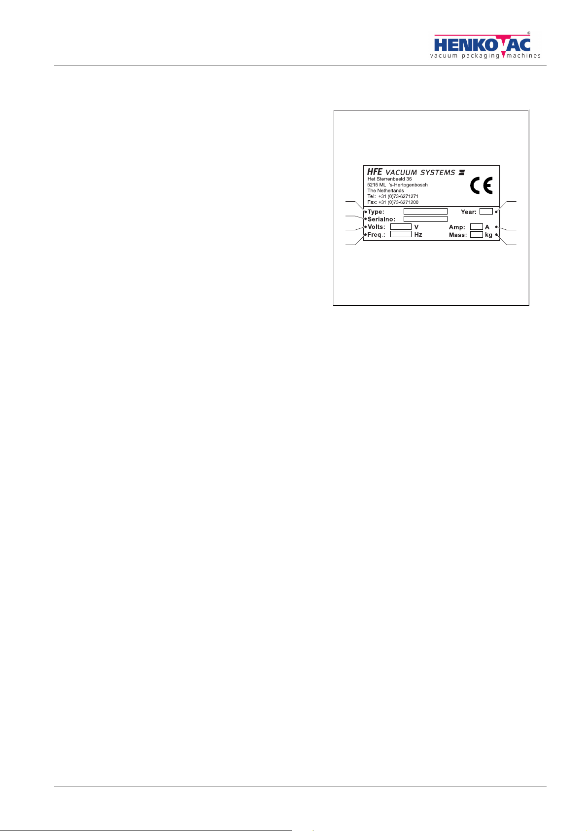
DENTIFICATION OF THE MACHINE
The identification plate contains the following data:
A Type
B Serial number
C Year of manufacture
D Number of phases-
Voltage
Volt V
E Frequency Hertz Hz
F Current Ampere A
G
Weight kilogram kg
E
A
B
D
G
C
F

CONTENTS
96.06.5.0805-IM-GB/11.06 5
CONTENTS
PREFACE..........................................................................................................................................3
SAFETY INSTRUCTIONS AND DANGER WARNINGS...................................................................6
SAFETY REGULATIONS IN THE DIPTANK....................................................................................8
MACHINE AND THE ENVIRONMENT..............................................................................................9
1.THE DIPTANK..............................................................................................................................10
1.1.
E
XECUTION DIPTANK
..................................................................................................................10
1.2.
M
AIN COMPONENTS DIPTANK
......................................................................................................10
2.INSTALLATION............................................................................................................................11
2.1.
I
NSTALLATION
...........................................................................................................................11
2.2.
P
REPARE FOR USE
....................................................................................................................11
3.CONTROL ....................................................................................................................................12
3.1.
C
ONTROL PANEL
.......................................................................................................................12
3.2.
S
WITCHING ON
..........................................................................................................................12
3.3.
T
HERMOSTAT
............................................................................................................................12
3.3.1.
Adjust working temperature................................................................................12
3.3.2.
Control working temperature..............................................................................13
3.3.3.
Control working thermostat ................................................................................13
3.4.
U
SE
..........................................................................................................................................13
4.MAINTENANCE ...........................................................................................................................14
4.1.
C
LEANING OF THE TANK
.............................................................................................................14
4.2.
C
ONNECTION CABLE
..................................................................................................................14
5.FAULTS........................................................................................................................................15
6.TECHNICAL DETAILS.................................................................................................................16
7.CE-DECLARATION................................................................... Fout! Bladwijzer niet gedefinieerd.

SAFETY INSTRUCTIONS
6 96.06.5.0805-IM-GB/11.06
SAFETY INSTRUCTIONS AND DANGER WARNINGS
G
ENERAL
The manufacturer accepts no liability whatsoever for damage or injury caused by not (strictly) following the safety
directions and instructions in this manual, or carelessness during the installation, use, maintenance and repair of
the machines identified on the front of this document and any accompanying options.
The owner of the machine is responsible at all times for observing the locally applicable safety
regulations and guidelines.
Obey all safety instructions and guidelines as given in this manual.
U
SER MANUAL
Every user should be informed of the contents of this manual and follow the instructions in it carefully.
Management must train personnel on the basis of this manual and obey all directions and indications.
They should not be damaged or removed and they should remain present and readable throughout the entire
life span of the machine.
Replace or repair unreadable or damaged pictograms, warnings and instructions immediately.
Always keep the manual in the proximity of the machine.
P
ICTOGRAMS AND INSTRUCTIONS ON THE MACHINE
The pictograms, warnings and instructions that have been attached to the machine are part of the safety
measures taken.
They should not be damaged or removed and they should remain present and readable throughout the entire
life span of the machine.
Replace or repair unreadable or damaged pictograms, warnings and instructions immediately.
SAFETY INSTRUCTIONS
96.06.5.0805-IM-GB/11.06 7
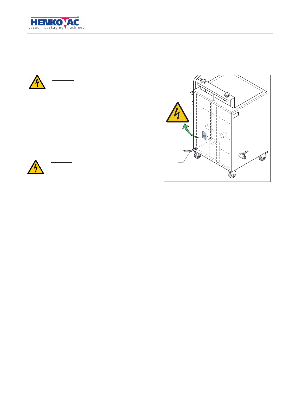
P
ICTOGRAMS ON THE DIPTANK
On the machine the following pictograms are attached.
DANGER
Before opening: remove the plug from the wall
socket!
Only qualified personnel are allowed to open
the unit.
C
ONNECTIONS TO THE DIPTANK
The diptank is equipped with a power cable. A plug
suitable for the local power requirements has to be
connected to the power cable.
DANGER
The plug can only be connected by qualified
electricians only.
U
SE OF THE MACHINE
*1
The diptank has been designed to shrink shrink bags, in which products have been packed under vacuum,
under influence of head.
Any other or extended use is not according to the purpose. The manufacturer accepts no liability for damage or
injury resulting from this. Use the machine only in a technically perfect condition, in accordance with the purpose
described above.
T
ECHNICAL SPECIFICATIONS
The specifications stated in this manual may not be changed.
M
ODIFICATIONS
Modifications of (parts of) the diptank are not allowed.
By modifications executed by others than HFE vacuum systems b.v.:
•The guarantee expires
•The liability of the manufacturer expires
*1 The “Use in accordance with purpose” as established in EN 292-1 is the use for which the technical product is suitable according to the
statement by the manufacturer – including his directions in the sales brochure -. When in doubt it is the use that appears to be the most
usual from the construction, model and function of the product. Use in accordance with the purpose means observing the instructions in
the user manual.
A

SAFETY INSTRUCTIONS IN THE DIPTANK
8 96.06.5.0805-IM-GB/11.06
SAFETY REGULATIONS IN THE DIPTANK
BOILING DYR SECURITY
The machine is equipped with a float switch (A) that
secures the diptank against boiling dry. Because of the
vaporizing of warm water and as there is always some
water left in the packing, the water level in the diptank will
decrease. When the water level will be too low, the
heating will switch off automatically.
Switching on again of the diptank:
•Add water.
•Press the pushbutton to switch on the diptank.
TEMPERATURE SENSOR
The temperature sensor (B) in the diptank guards the
temperature set.
U
SE
•Inspect the diptank before use and check it for damage.
•Remove the plug from the diptank from the wall socket after every use. Because of this you will not have
tension on the diptank.
•Never use sharp objects to operate the keys.
•Do not allow unauthorized persons into the working environment.
•Always ensure there is adequate ventilation, especially in confined places
•Wear clothing that is suitable for the work. Loose clothing or jewelry can get between the cover and the
vacuum chamber.
•Never use the machine in an environment in which there is an explosion risk.
•Replace the supply cable if it is damaged
•Make sure that the supply cable cannot be damaged by trapping this cable.
H
YGIENE
•Cleaning the machine is of the utmost importance when food products are wrapped. Clean the machine
regularly and thoroughly, preferably every day, sees “maintenance”.
•Work hygienically and prevent direct contact between the product and the machine as much as possible.
•Keep the operating controls free of dirt and grease.
•Hold long hair together.
S
ERVICE
,
MAINTENANCE AND REPAIR
A clear distinction is made in this manual between the service, maintenance and repair work that can be carried out by
the user, and that which is reserved for trained and qualified service technicians only.
A
B
SAFETY INSTRUCTIONS IN THE DIPTANK
96.06.5.0805-IM-GB/11.06 9
•Make sure there is adequate lighting.
•Always switch off the machine at the main switch during maintenance and/or repairs and/or remove the plug
from the socket.
•Observe the maintenance intervals specified. Overdue maintenance can lead to high costs for repair and
servicing and the right to guarantee can be lost.
•Always use parts, materials, lubricants and service techniques approved by the manufacturer.
•Never use worn tools and do not leave any tools inside the machine.
•Do not carry out service, maintenance or repair work to the machine, when it is indicated that the dealer or
qualified service technician should carry it out.
•Always have a recognized Henkovac dealer carry out repair and maintenance work.
•Safety measures that have been removed in order to carry out service, maintenance or repairs must be
refitted immediately after this work and they must be checked for correct operation.
MACHINE AND THE ENVIRONMENT
PACKING
The packing that is for the transportation and protection of the machine is mainly made of cardboard
and/or wood, which are suitable for recycling. Do not dispose of the packaging as industrial waste but
ask the sanitation department of your local government authority where you can hand in the material.
MACHINE
When you dispose of your machine, it can still contain valuable substances and materials. Do not
dispose of the machine as industrial waste, but enquire at your local government authority about the
possibilities for recycling or environmentally friendly disposal of the material.
•Most parts of the machine have been manufactured from stainless steel and can be disposed of as
scrap metal in the normal way. From health and environmental considerations, no asbestos has been
used.
•The printed circuit boards and the components mounted on them are electronic waste.. Deliver old
printed circuit boards to specialized companies for environmentally friendly processing.
OIL
Ask the sanitation department of your local government authority where you should take the used oil for
an environmentally friendly processing.

THE DIPTANK
10 96.06.5.0805-IM-GB/11.06
1. THE DIPTANK
1.1. Execution diptank
In a diptank products can be final processed which are vacuum packed in shrink bags. Shrink bang are vacuum
bags which shrink when being heated.
A diptank is a machine with a water reservoir. The water will be heated till the adjusted temperature. After
vacuum packing of products the package shows folds and wrinkles. When a packed product in a shrink bag is
dipped in hot water, the pouch shrinks and straightens out the folds. The result is a tight packed product with a
second skin effect.
In the diptank there is a platform, where products should be placed on when it is in its highest position. After
placing the products on the platform, the push button has to be pressed. The platform will automatically descend
and rise automatically where the products have been dipped in the warm water. The final processed products
have to be removed manually from the platform.
1.2. Main components diptank
A. Control panel
B. Platform
C. Wheel with brake
D. Wheel
E. Drainer
F. Connection cable
G. Identification plate
G
F
E
D
A
C
B
INSTALLATION
96.06.5.0805-IM-GB/11.06 11
2. INSTALLATION
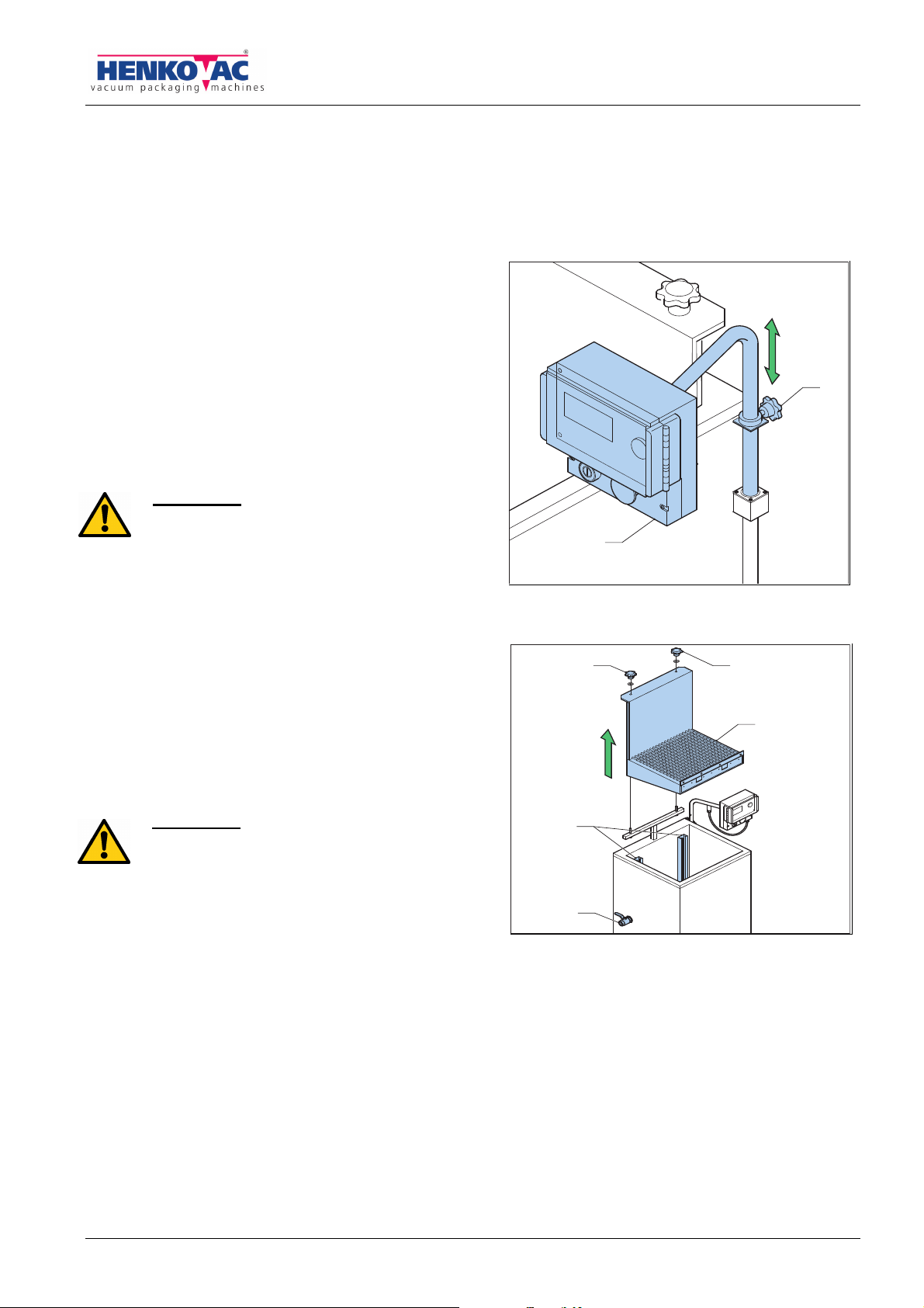
2.1. Installation
1. Unpack the diptank.
2. Level the machine on a flat firm surface.
3. Apply the brakes of the wheels
4. Have a qualified electrician connect a suitable plug to
the connection cable.
5. Adjust the height of control panel:
Loosen the star button (A) and position the control
panel (B) at a suitable height and angle, in order to
work easier with the diptank.
ATTENTION
Never place the diptank before an entrance, exit
or emergency exits that are meant for
emergency services.
2.2. Prepare for use
1. Make sure that the draw-off tap (C) is closed.
2. Fill the tank with water, until about 4 to 6 cm. under
the platform (B), if the platform is positioned in the
upper level.
3. Connect the diptank to a socket.
ATTENTION
Pay attention to the dimensions of the vacuum
packed products. If the packed product will go
completely under water, no water may flow over
of the tank.
B
A
D
B
AA
C
CONTROL
12 96.06.5.0805-IM-GB/11.06
3. CONTROL
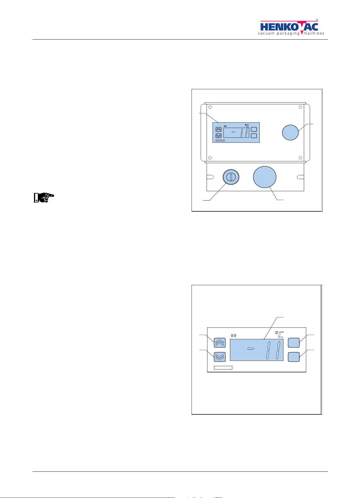
3.1. Control panel
A. Temperature control
B. Control lamp
C. Pulse button in order to have the diptank make one
cycle.
D. Start button for the heating
3.2. Switching on
1. Press the start button (D): the heating will be
switched on. The control lamp (B) will burn.
The heating of the water takes 45-60 minutes.
2. Press the pulse button (C): the platform makes one
cycle and stops in the upper position. Check the water level, see § 2.2.
3. Open the transparent cover.
4. Adjust the required water temperature.
3.3. Thermostat
A. Display
B. Function button “fnc”
C. Function “set”
D. Function “down”
E. Function “up”
3.3.1.Adjust working temperature
1. Press the button “set” (C) for 1 second.
The display (A) will show “SET”.
2. Press “set” again. The display shows the adjusted
value.
3. Adjust the temperature to 90°C by pressing the
button “op” (E) or button “down” (D).
4. Press twice on “fnc” (B) to store the adjusted value.
This ends the adjustments.
fnc
set
out
D
A
B
C
out
set
fnc
B
A
C
E
D

CONTROL
96.06.5.0805-IM-GB/11.06 13
Remarks
•The display shows the measured temperature. This is the actual temperature, not the adjusted temperature.
•If you have not pushed a button during 15 seconds, the display automatically returns, without storing the
value.
3.3.2.Control working temperature
1. Press two times on “set”. In the display the adjusted temperature will be shown.
3.3.3.Control working thermostat
1. Adjust the working temperature at about 3°C above the surroundings temperature.
In the display a point will lighten, that shows that the relays of the controller will be changed over.
2. Adjust the working temperature at about 3°C below the surroundings temperature.
If the point extinguishes, the working of the thermostat is okay.
3. Adjust the correct working temperature again, see § 3.3.1.
3.4. Use
If the water is on temperature is, the diptank can be
used.
1. Place the to be final processed vacuum packed
product (A) on the platform (B).
2. Push the pulse button (C). The platform makes one
cycle: one down and one up. In this upper position
the platform will stop.
3. Remove the final processed product from the
platform.
A new to be final processed vacuum packed product
can be placed on the platform.
DANGER
During the cycle the platform moves down
and up. Keep away from moving parts in
order to prevent oppressing.
B
C
A
MAINTENANCE
14 96.06.5.0805-IM-GB/11.06
4. MAINTENANCE
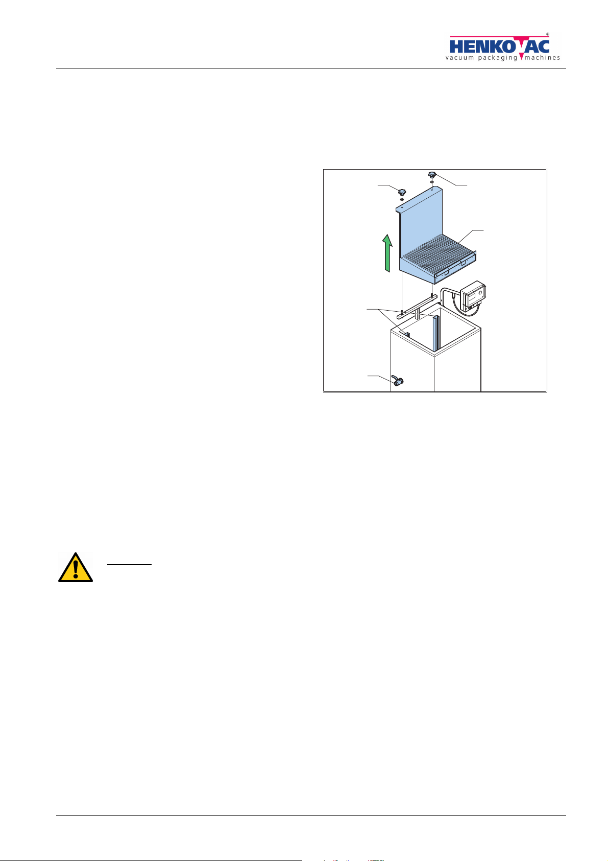
4.1. Cleaning of the tank
Daily maintenance in order to work hygienically it is
necessary to:
•Clean the tank
•Refresh the water
1. Remove the plug from the socket. Because of this
the diptank, so including the heating, will be
switched off.
2. Loosen the star buttons (A).
3. Take the platform (B) out of tank.
4. Clean the platform.
5. Draw off the water in the tank, by opening the
draw-off tap (C). Make sure of a good discharge of
the water.
6. Close the draw-off tap.
7. Attach the platform: the guide rollers have to slide
in the rails (D).
8. Tighten the platform with the star buttons.
9. Fill the diptank with clean water before starting the new production, see § 2.2.
4.2. Connection cable
1. Check the connection cable regularly for damages.
DANGER
Have the dealer replace a damaged connection cable immediately.
D
B
AA
C

FAULTS
96.06.5.0805-IM-GB/11.06 15
5. FAULTS
Faults Cause Remedy
The plug is not in the socket. Plug the plug into the socket.
(Earth leaking) protection in the
electric cabinet has tripped.
Check the electric cabinet.
A fuse(s) in the electric cabinet is
defective.
Check the electric cabinet.
A fuse(s) in the machine is defective. Consult your dealer.
The motor protection of the machine
is switched off.
Consult your dealer.
The diptank does not
work.
There is a break in the connection
cable.
Have the connection cable been replaced
by authorized electrician.

TECHNICAL DETAILS
16 96.06.5.0805-IM-GB/11.06
6. TECHNICAL DETAILS
Type HV-40/60 HV-55/75
Dimensions and weight
Depth 675 mm 800 mm
Width 860 mm 1020 mm
Height 1350 mm 1350 mm
Weight 106 kG 130 kG
Dimensions and weight of the packed machine
Depth 960 mm 1035 mm
Width 950 mm 1180 mm
Height 1260 mm 1375 mm
Weight 157 kG 190 kG
General information
Platform Length 580 mm 730
Width 410 mm 530
Contents diptank 110 ltr 180 ltr
Maximum water volume 75 – 80 ltr 100 – 140 ltr
Connection draw-off tap 1" female
Electrical connections
Voltage, Current, Frequency See the identification plate, see “identification of the machine”.
Capacity 9 kW 15 KW
Phases 200V – 240V 3 phases
Phases 380V – 415V 3 phases + neutral
Frequency 50/60 Hz
Voltage tolerance ± 10 %
Voltage date was not included in this summary, because these are dependent on the electricity
supply of the country that the machine is intended for. The voltage dates are given on the machine
identification plate (see “identification of the machine”),
Dimensions and weights are for the standard model machines.

96.06.5.0805-IM-GB/11.06 17
7. CE-DECLARATION
CE-VERKLARING VAN OVEREENSTEMMING
CE-DECLARATION OF CONFORMITY
CE-KONFORMITÄTSERKLÄRUNG
DECLARATION DE CONFORMITÉ CE
DICHIARAZIONE DI CONFORMITA'CE
Wij,
We, HFE vacuum systems bv.
Wir, Het Sterrenbeeld 36, 's-Hertogenbosch
Nous, The Netherlands
Noi,
verklaren geheel onder eigen verantwoordelijkheid dat de produkten,
declare under our sole responsibility that the products,
erklären in alleiniger Verantwortung, daß die Produkte,
déclarons sous notre responsabilité, que les produits,
Dichiariamo sotto la nostra responsabilità che las macchinas
Henkovac vacuum packing machines
waarop deze verklaring betrekking heeft, in overeenstemming is met de volgende Europese Richtlijnen:
to which this declaration relates, complies with the requirements of the following European Directives:
auf die sich diese Erklärung bezieht, folgende Europäischer Richtlinie entspricht:
auquel se réfère cette déclaration, est conforme aux Directives Européennes:
alla quale si riferisce questa dichiarazione, è conforme alle Direttive Europee:
•the machine guideline: 2006/42/EG
•the EMC-guideline: 2004/108/EG
Conformiteit is aangetoond door overeenstemming met de volgende normen:
Conformity is testified by complete adherence to the following standards:
Die Übereinstimmung wird nachgewiesen durch die vollständige Einhaltung folgender Normen:
La conformité est demonstrée par la conformité intégrale avec les normes suivantes:
La conformità è dimostrata dalla conformità alle sequenti norme:
NEN-EN-ISO 12100-1
NEN-EN-ISO 12100-2
NEN-EN-ISO 14121-1
NEN-EN-ISO 13857
NEN-EN 60204-1
E.H. Goudsmid
Managing Director
The Netherlands, 's-Hertogenbosch, June 2011

This manual suits for next models
1
Table of contents


