HGM COMPUSHIFT Mini User manual

COMPUSHIFT Mini Manual
COMPUSHIFT Mini Manual
Exported on 12/08/2020

COMPUSHIFT Mini Manual – COMPUSHIFT Mini Manual
– 2
Table of Contents
1 Preparing for Your Installation ..............................................................................6
1.1 Vehicle Preparation......................................................................................................................6
1.2 A Word About Adjusting the TV Cable .........................................................................................6
1.3 GM 700R4 / 2004R.........................................................................................................................7
1.4 Chrylser A518 / A618 ....................................................................................................................7
1.5 Additional Planning .....................................................................................................................7
1.6 Other Considerations...................................................................................................................7
1.7 Tools You Will Need......................................................................................................................8
1.8 Tools You May Need.....................................................................................................................8
1.9 Unpacking and Inspecting the Kit ...............................................................................................8
1.9.1 Kit Contents................................................................................................................................................................ 8
1.10 Assembling the Speed Sensor ...................................................................................................11
2 Installing the COMPUSHIFT Mini .........................................................................14
2.1 Installation Inside the Vehicle ...................................................................................................14
2.1.1 Locating and Mounting the Controller.................................................................................................................... 14
2.1.2 Routing the Wiring Harness ..................................................................................................................................... 14
2.1.3 Connecting to Vehicle Power................................................................................................................................... 15
2.1.4 Connecting to an Electronic Speedometer............................................................................................................. 16
2.2 Installation on GM 700R4 / 2004R..............................................................................................16
2.2.1 Installing the Pressure Sensor................................................................................................................................. 16
2.2.2 Installing the Speed Sensor..................................................................................................................................... 18
2.2.3 Installing the Wiring Harness................................................................................................................................... 20
2.3 Installation on Chrysler A518/46RH and Chrysler A618/47RH .................................................22
2.3.1 Installing the 3rd Gear Pressure Switch.................................................................................................................. 22
2.3.2 Installing the Speed Sensor..................................................................................................................................... 23
2.3.3 Installing the Wiring Harness................................................................................................................................... 26
2.3.4 Install / Connect the Throttle Position Sensor ....................................................................................................... 28
2.4 Using the Display........................................................................................................................28
2.4.1 Navigation Mode ...................................................................................................................................................... 29
2.4.2 Edit Mode.................................................................................................................................................................. 29

COMPUSHIFT Mini Manual – COMPUSHIFT Mini Manual
– 3
2.5 System Checkout .......................................................................................................................29
2.5.1 Power On!................................................................................................................................................................. 29
2.5.2 Pressure Sensor Check ............................................................................................................................................ 30
2.5.3 Speed Sensor Check ................................................................................................................................................ 30
2.6 Throttle Position Sensor Calibration (GM)................................................................................30
2.6.1 Introduction ............................................................................................................................................................. 30
2.6.2 Calibration Procedure.............................................................................................................................................. 30
2.6.3 Diagnosing Problems with TPS Calibration............................................................................................................ 33
2.7 Throttle Position Sensor Calibration (Chrysler) .......................................................................33
2.7.1 Introduction ............................................................................................................................................................. 33
2.7.2 Calibration Procedure.............................................................................................................................................. 33
3 Tuning and Driving...............................................................................................35
3.1 Driving with COMPUSHIFT Mini.................................................................................................35
3.2 Status Screens............................................................................................................................35
3.2.1 Vehicle Speed ........................................................................................................................................................... 35
3.2.2 Throttle Position ...................................................................................................................................................... 36
3.2.3 Transmission Pressure (GM Only) ........................................................................................................................... 36
3.2.4 Overdrive .................................................................................................................................................................. 36
3.2.5 Torque Converter Clutch ......................................................................................................................................... 37
3.3 Torque Converter Clutch Parameters (GM) ..............................................................................37
3.3.1 Introduction ............................................................................................................................................................. 37
3.3.2 Torque Converter Clutch Lock Throttle Position ................................................................................................... 38
3.3.3 Torque Converter Clutch Unlock Throttle Position................................................................................................ 38
3.3.4 Torque Converter Clutch Lock Speed ..................................................................................................................... 38
3.3.5 Torque Converter Clutch Unlock Speed ................................................................................................................. 39
3.3.6 Torque Converter Clutch Lock Delay ...................................................................................................................... 39
3.4 Torque Converter Clutch Parameters (Chrysler)......................................................................39
3.4.1 Introduction ............................................................................................................................................................. 39
3.4.2 Torque Converter Clutch Enable Gear .................................................................................................................... 40
3.4.3 Torque Converter Clutch Lock Throttle Position ................................................................................................... 41
3.4.4 Torque Converter Clutch Unlock Throttle Position................................................................................................ 41
3.4.5 Torque Converter Clutch Lock Speed ..................................................................................................................... 41
3.4.6 Torque Converter Clutch Unlock Speed ................................................................................................................. 41
3.4.7 Torque Converter Clutch Lock Delay ...................................................................................................................... 42

COMPUSHIFT Mini Manual – COMPUSHIFT Mini Manual
– 4
3.5 Overdrive Parameters (Chrysler)...............................................................................................42
3.5.1 Introduction ............................................................................................................................................................. 42
3.5.2 Minimum Overdrive Speed...................................................................................................................................... 42
3.5.3 Wide Open Throttle Overdrive Speed ..................................................................................................................... 42
3.6 Other Status Information and Adjustments .............................................................................43
3.6.1 Throttle Position Sensor Voltage ............................................................................................................................ 43
3.6.2 Throttle Position Sensor Calibration Low Voltage ................................................................................................. 43
3.6.3 Throttle Position Sensor Calibration High Voltage ................................................................................................ 43
3.6.4 Speedometer Adjustment ....................................................................................................................................... 43
3.6.5 Speed Sensor Calibration ........................................................................................................................................ 44
3.6.6 Measurement Units.................................................................................................................................................. 44
3.6.7 Factory Defaults ....................................................................................................................................................... 44
4 Diagnostics ...........................................................................................................45
5 Additional Guides and Information.....................................................................48
5.1 Connector Pinouts .....................................................................................................................48
5.1.1 Connector Layout..................................................................................................................................................... 48
5.1.2 Pinout Chart ............................................................................................................................................................. 48

1 https://hgmelectronics.atlassian.net/wiki/download/attachments/1127514121/
COMPUSHIFT%20Mini%20Quick%20Install%20Guide.pdf?
api=v2&cacheVersion=1&modificationDate=1604171838303&version=1
COMPUSHIFT Mini Manual – COMPUSHIFT Mini Manual
– 5
•
•
•
•
•
•
•
•
•
Thanks for purchasing and installing the COMPUSHIFT Mini.
If you want to get started quickly, please read theCOMPUSHIFT Mini Quick Install Guide1.
The COMPUSHIFT Mini is a standalone plug-and-play system designed to control the torque converter clutch and
overdrive on selected transmissions including:
GM 700R4
GM 2004R
Chrysler A518 / 46RH
Chrylser A618 / 47RH
Unlike other control modules that use vacuum switches or a simple delay timer, the COMPUSHIFT Mini uses throttle
position and vehicle speed to optimize its shifting and clutch control.
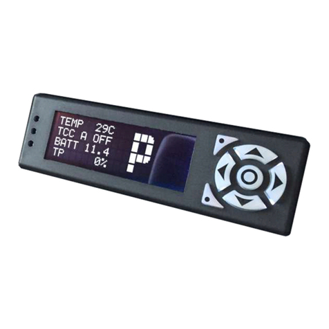
A built-in display and keypad lets the user adjust and tune for their specific application, and diagnose problems
should they occur.
The COMPUSHIFT Mini uses a miniaturized version of same control software and electronics as HGM's COMPUSHIFT
II.
Preparing for Your Installation(see page 6)
Installing the COMPUSHIFT Mini(see page 14)
Tuning and Driving(see page 35)
Diagnostics(see page 45)
Additional Guides and Information(see page 48)

COMPUSHIFT Mini Manual – COMPUSHIFT Mini Manual
Preparing for Your Installation– 6
1.
•
•
2.
•
•
1 Preparing for Your Installation
1.1 Vehicle Preparation
Prior to installation, you should ensure that your powertrain, engine, transmission, drive shaft, rear axle, are all in
good working condition.
The vehicle's electrical system should be properly maintained and working correctly. Battery voltage should be 14.4
- 14.7 volts while the engine is running.
The transmission should shift smoothly and correctly through its gears, and the shift linkage should be correctly
adjusted.
Your transmission must have a properly-calibrated speedometer gear.
COMPUSHIFT Mini uses the industry standard 1000 turns per mile speedometer cable speed to determine
speed.
1.2 A Word About Adjusting the TV Cable
A properly-adjusted TV cable can make a world of difference in transmission and engine performance.
Two things are important for setting the TV cable:
Removing the slack
Proper slack in the cable means that the cable has a little bit of tension with the throttle is closed, but
no so much that it changes in the main line pressure.As soon as the throttle starts to open, the line
pressure should start to increase.
Proper travel in the cable means that the cable extends its full range when the throttle is moved to
the fully open position, but no further.
Setting the travel
If the cable fails to move the full range, then full line pressure won't be reached, the transmission
may slip, and also the shift points may be too low.
A cable that moves too much will cause hard shifts that are too soon, can break the linkage in
transmission, and can also prevent achieving a fully open throttle.
COMPUSHIFT Mini cannot properly operate a malfunctioning transmission. A malfunctioning
transmission may damage COMPUSHIFT Mini and void your warranty.
Your transmission must be properly installed and in good mechanical condition before using COMPUSHIFT
Mini.
A qualified transmission repair shop can inspect, clean, install, and/or rebuild your transmission as
required.
If you have any questions about the condition or type of transmission, please contact a qualified
transmission repair facility, HGM Headquarters, or one of our distributors for a recommendation.

2 http://bowlertransmissions.com/p/64/tru-shift-throttle-correction-arm-system
COMPUSHIFT Mini Manual – COMPUSHIFT Mini Manual
Preparing for Your Installation– 7
•
•
•
•
•
•
•
•
•
•
•
Getting both of these right means having the right combination of cams and arm length on the throttle linkage.
Some accessory kits, like theBowler Tru-Shift2allow full adjustment and correction of TV cable problems.
The COMPUSHIFT Mini is a valuable aid in doing TV cable adjustment because it can display line pressure on screen
in real-time. The cable travel and slack can easily be adjusted to their proper limits because:
When the pressure starts to increase, the slack has been removed.
When the pressure stops increasing, the cable is at its full extension.
1.3 GM 700R4 / 2004R
During the years that GM built these transmissions, a number of different combinations of internal switches and
wiring looms were fitted. The transmission must have a proper internal wiring harness. It must use a 4th gear
pressure switch that is normally open and switches to ground when 4th gear is engaged.
The following are recommended wiring looms:
Rostra350-0045
NATPRO 51870U
TRANSTAR 54425B
The following are recommended 4th gear switches:
NATPRO 51876
TRANSTAR 74411B
1.4 Chrylser A518 / A618
Your engine must have a throttle position sensor in order to use the controller. Aside from being in good, working
mechanical condition, no specific preparation is required for this transmission.
1.5 Additional Planning
Prior to installation, you'll also need to decide:
Where tomount your COMPUSHIFT Mini Controller.
Where to install the firewall grommets for your wiring harnesses.
How toroute the wiring harnessesto the engine and transmission.
1.6 Other Considerations
COMPUSHIFT Mini can provide an electronic signal tooperate an electronic speedometer.

COMPUSHIFT Mini Manual – COMPUSHIFT Mini Manual
Preparing for Your Installation– 8
•
•
•
•
•
•
•
•
•
•
•
•
•
•
•
•
Refer to theCOMPUSHIFT Mini Quick Install Guide, also included in the packaging, to get an overview of all
the components.
1.7 Tools You Will Need
1/8" or 3/16" flat blade screwdrivers
Drill and small drill bit assortment
Socket / open-end wrench assortment
Wire cutters / wire stripping pliers
Soldering iron and solder or wire crimping pliers
PTFE / Teflon sealant or tape
1.8 Tools You May Need
Depending on the installation, you may also need:
File
Tin snips
Center punch
Sheet metal tools
Insulating tape
Wire spade lugs
Wire crimp connectors
1.1875" hole saw or chassis punch
Volt/ohm-meter
1.9 Unpacking and Inspecting the Kit
1.9.1 Kit Contents
The kit ships with all of the parts that should be needed for the installation.
The basic kit contains the following items:
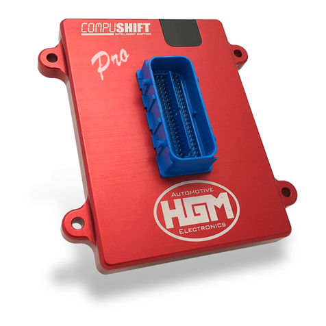
COMPUSHIFT Mini Controller with keypad:

COMPUSHIFT Mini Manual – COMPUSHIFT Mini Manual
Preparing for Your Installation– 9
Wiring harness, specific to the kit:
Hydraulic pressure sensor (GM only):

COMPUSHIFT Mini Manual – COMPUSHIFT Mini Manual
Preparing for Your Installation– 10
Third gear pressure switch (Chrysler only):
Speed sensor and fittings:

COMPUSHIFT Mini Manual – COMPUSHIFT Mini Manual
Preparing for Your Installation– 11
•
•
•
•
Hook and loop fasteners, terminals and cable ties:
1.10 Assembling the Speed Sensor
A little bit of preparation is required before installing the speed sensor on the transmission.
The speed sensor kit has four pieces:
The sensor
A small section of drive cable
A washer
A cable nut

COMPUSHIFT Mini Manual – COMPUSHIFT Mini Manual
Preparing for Your Installation– 12
The assembly is straightforward.
The small end of the nut attaches to the small end of the speed sensor.
The section of drive cable goes into the speed sensor through the nut.
The washer goes into the large end of the nut, leaving the drive cable protruding.
The finished assembly looks like this:

COMPUSHIFT Mini Manual – COMPUSHIFT Mini Manual
Preparing for Your Installation– 13

COMPUSHIFT Mini Manual – COMPUSHIFT Mini Manual
Installing the COMPUSHIFT Mini– 14
1.
2.
3.
4.
5.
6.
7.
2 Installing the COMPUSHIFT Mini
Installing the COMPUSHIFT Mini is a straightforward operation if you are familiar with working on cars. A simplified
breakdown is as follows:
Mount the controller in the vehicle.
Install the wiring loom in the vehicle, routing the loom though a hole in the firewall.
Install the sensors and switches on the transmission.
Connect the wiring loom to the transmission and secure it.
Install the throttle position sensor (Chrysler only).
Calibrate the throttle position sensor.
Drive the vehicle.
You can get started with Installation Inside the Vehicle(see page 14).
2.1 Installation Inside the Vehicle
2.1.1 Locating and Mounting the Controller
Look inside your passenger compartment and decide where to mount the COMPUSHIFT Mini controller.
It needs to be in a dry, cool, secure location -- thefarther awayfrom a heater outlet, the better.
The controller needs to be located in the vehicle near a source of ignition-switched power.
One good place is under the passenger or driver-side dash, but you can also mount the controller on the floor pan
or under a seat – provided there's at least 1" of clearance and free-flowing air around all sides. Make sure the engine
exhaust system is not heating the spot where you plan to mount it.
Carefully consider the mounting location. The unit isnot waterproofso never mount the controller in the
engine compartment or under the vehicle. Extreme shock and vibration, high temperature, or high input
voltage can damage the unit. You will need to make adjustments to COMPUSHIFT Mini during installation, so
be sure that the wiring loom will reach where you can read and adjust it.
A section of tape with hook-and-loop fasteners (Velcro) has been provided to mount the controller. Apply the hook
side of the tape to the back of the controller. Apply the loop side of the tape to mounting location.
For now, leave the controller where it can be usedduring final checkout(see page 29),calibration(see page 30)and
tuning(see page 35).
2.1.2 Routing the Wiring Harness
The COMPUSHIFT Mini must be mounted inside the vehicle, so the wiring harness to the transmission needs to be
routed through the firewall.

COMPUSHIFT Mini Manual – COMPUSHIFT Mini Manual
Installing the COMPUSHIFT Mini– 15
The wiring harness is equipped with suitable rubber grommet that can moved along the wire harness to the desired
position.
To fit the grommet, you will have to drill or punch a 1.25"hole through the firewall in an appropriate location. The
controller-side connector at the end of the wiring loom is larger than the 1.25" hole, so it the harness must be
pushed through the firewall from inside the vehicle rather than up from the transmission.
Once the harness is though, it can be routed along the right side of the transmission and installed.
2.1.3 Connecting to Vehicle Power
The power section of the wiring loom is a separate branch from the section that goes to the transmission.
This lets you mount the controller away from the power source as needed.

COMPUSHIFT Mini Manual – COMPUSHIFT Mini Manual
Installing the COMPUSHIFT Mini– 16
The power section of the wiring loom has a dedicated fuse, and can be shortened as necessary.
Connect the red wire to a source of switched 12 volt power.
Connect the black wire to a good ground connection, preferably using a bolt to clean sheet metal through the
supplied lug.
2.1.4 Connecting to an Electronic Speedometer
The COMPUSHIFT Mini can drive an electronic speedometer.
If desired, connect the purple wire with a white stripe to the signal input of your electronic speedometer.
2.2 Installation on GM 700R4 / 2004R
2.2.1 Installing the Pressure Sensor
Locate the line pressure plug test port on the left side of the transmission, immediately behind the bellhousing.
The test port is usually capped off with a 1/8" NPT plug:

COMPUSHIFT Mini Manual – COMPUSHIFT Mini Manual
Installing the COMPUSHIFT Mini– 17
Clean the area around the plug and remove it using an appropriately-sized socket or wrench:
Put a small amount of PTFE / Teflon sealant on the pressure sensor or wrap it with PTFE / Teflon pipe sealant tape.
Thread the pressure sensor into the port. Tighten the pressure sensor until it is finger-tight, then use a wrench to
tighten it another 1.5 to 3 turns, depending on feel.
Do not overtighten! The transmission case is made of aluminum and the pressure sensor is made of brass. Both are
soft metals and will strip easily.

COMPUSHIFT Mini Manual – COMPUSHIFT Mini Manual
Installing the COMPUSHIFT Mini– 18
2.2.2 Installing the Speed Sensor
As installed in the vehicle, the transmission should have speedometer cable attached to the speedometer drive
output of the trailhousing.
Clean the area around the end of the cable, and unscrew the cable nut from the drive output:
Remove the cable and set it aside. The drive output should look like this:

COMPUSHIFT Mini Manual – COMPUSHIFT Mini Manual
Installing the COMPUSHIFT Mini– 19
Locate the speed sensor you assembled earlier:
Screw the speed sensor into the speedometer drive on the tailhousing, being sure to engage the short cable inside
the drive.
Snug the nut securely with a wrench ensuring that the speed sensor wires point toward the front of the vehicle:

COMPUSHIFT Mini Manual – COMPUSHIFT Mini Manual
Installing the COMPUSHIFT Mini– 20
Reattach the speedometer cable to the output of the speed sensor:
2.2.3 Installing the Wiring Harness
Earlier, you pushed the wiring harness through the firewall and installed the grommet. From the underside of the
vehicle, locate the wire harness and begin routing it toward the right rear side of the transmission. Locate the
transmission wiring socket, shown below:
Table of contents
Other HGM Controllers manuals
