Hi-flying HF211 User manual

HF2111 GPRS Serial Server User Manual
Shanghai High-Flying Electronics TechnologyCo., Ltd 1/29
HF2111
GPRS Serial Server User Manual
V1.4
OverviewofCharacteristic
Support Four Frequency Bands, Global Standard(850/900/1800/1900MHz)
Support GSM/GPRS (No 3G Network) and 2G/3G/4G CMCC or CUCC SIM Card
Support Max 3 channel TCP/UDP.
Support Multiple Work Mode(Transparent Transmission/AT Commands)
Embedded RS232/RS422/RS485 to GPRS interface
Size: 95 x 65 x 25mm
Single 5~36V DC Power Supply

HF2111 GPRS Serial Server User Manual
Shanghai High-Flying Electronics TechnologyCo., Ltd 2/29
CONTENT
List Of Figures..................................................................................................................... 4
List Of Tables......................................................................................................................4
History.................................................................................................................................4
1. PRODUCT OVERVIEW ............................................................................................5
1.1 Basic Parameters........................................................................................... 5
1.2 Hardware Introduction....................................................................................6
1.2.1. Interface Description......................................................................................6
1.2.2. RS232 Interface............................................................................................. 7
1.2.3. RS485 Interface............................................................................................. 7
1.2.4. RS422 Interface............................................................................................. 7
1.2.5. Mechanical Size............................................................................................. 8
1.2.6. Order Information........................................................................................... 8
1.2.7. Package Information...................................................................................... 9
2. FUNCTION DESCRIPTION................................................................................... 10
2.1. Wireless Networking.................................................................................... 10
2.2. Work Mode...................................................................................................10
2.3.1. Support single and multiple connecton ....................................................... 10
3. IOTSerialTool...........................................................................................................11
3.1. Description...................................................................................................11
3.2. UI..................................................................................................................11
3.3. Operation Steps........................................................................................... 12
4. AT+INSTRUCTION INTRODUCTION..................................................................14
4.1. Configuration Mode......................................................................................14
4.1.1. Switch to Configuration Mode............................................................... 14
4.2. AT+Instruction Set Overview.......................................................................15
4.2.1. Instruction Syntax Format............................................................................15
4.2.2. AT+Instruction Set....................................................................................... 16
4.2.2.1. AT+E.............................................................................................. 17
4.2.2.2. AT+ENTM......................................................................................17
4.2.2.3. AT+VER ......................................................................................... 18
4.2.2.4. AT+APPVER..................................................................................18
4.2.2.5. AT+RELD....................................................................................... 18
4.2.2.6. AT+Z............................................................................................... 18
4.2.2.7. AT+CFGTF..................................................................................... 18
4.2.2.8. AT+FCLR.......................................................................................18
4.2.2.9. AT+H.............................................................................................. 19
4.2.2.10. AT+UART....................................................................................... 19
4.2.2.11. AT+UARTINTERVAL.....................................................................19
4.2.2.12. AT+UARTTYPE ............................................................................. 19
4.2.2.13. AT+USERHEAD ............................................................................ 20
4.2.2.14. AT+SOCKA....................................................................................20
4.2.2.15. AT+SOCKB....................................................................................20
4.2.2.16. AT+SOCKC....................................................................................21
4.2.2.17. AT+TCPALK................................................................................... 21
4.2.2.18. AT+TCPBLK................................................................................... 21
4.2.2.19. AT+TCPCLK..................................................................................22
4.2.2.20. AT+SOCKANUM............................................................................ 22
4.2.2.21. AT+SOCKBNUM............................................................................ 22
4.2.2.22. AT+SOCKCNUM...........................................................................22

HF2111 GPRS Serial Server User Manual
Shanghai High-Flying Electronics TechnologyCo., Ltd 3/29
4.2.2.23. AT+WANN......................................................................................22
4.2.2.24. AT+GETIP...................................................................................... 23
4.2.2.25. AT+HEART ....................................................................................23
4.2.2.26. AT+UPGRADE...............................................................................23
4.2.2.27. AT+GVER ......................................................................................23
4.2.2.28. AT+GCID........................................................................................ 23
4.2.2.29. AT+CIMI......................................................................................... 24
4.2.2.30. AT+CGSN......................................................................................24
4.2.2.31. AT+GSLQ.......................................................................................24
4.2.2.32. AT+LOGIN ..................................................................................... 24
4.2.2.33. AT+MODBUSPROTO....................................................................25
4.2.2.34. AT+SCRIPTUART.........................................................................25
4.2.2.35. AT+MOVESCRIPT.........................................................................25
5. TEST CASE.............................................................................................................. 26
5.1. Use SOCK A to connect to server............................................................... 26
5.2. Use SMS to Set Parameters........................................................................ 27
5.3. Use SMS to Upgrade Firmware...................................................................28
5.4. Use SMS to Upgrade HIS Script .................................................................28
APPENDIX A:CONTACT US............................................................................................ 29

HF2111 GPRS Serial Server User Manual
Shanghai High-Flying Electronics TechnologyCo., Ltd 4/29
LIST OF FIGURES
Figure 1. HF2111 Appearance...............................................................................6
Figure 2. RS232 Pin Defination(Male/Needle Type) .............................................7
Figure 3. HF2111 Mechanical Dimension..............................................................8
Figure 4. HF2111 Production Code Definition.......................................................9
Figure 5. GPRSwireless network.........................................................................10
Figure 6. HF2111 Default UART Port Parameters..............................................14
Figure 7. Switch to Configuration Mode............................................................... 14
Figure 8. ”AT+H” Instruction for Help ................................................................... 15
LIST OF TABLES
Table1. HF2111 Basic Parameters...................................................................... 5
Table2. HF2111 External Interface...................................................................... 6
Table3. RS232 Interface......................................................................................7
Table4. RS422 Connectioin.................................................................................8
Table5. Error Code Describtion......................................................................... 16
Table6. AT+Instruction Set List.......................................................................... 16
HISTORY
Ed. V1.0 12-29-2016 First Version.
Ed. V1.1 01-19-2017 Update PC Config IOTSerialTool
Ed. V1.2 02-10-2017 Update the appearance of the product, adjust the power input mark
Ed. v1.3 03-20-2017 Added register function and configuration instructions
Ed. v1.4 12-18-2017 Support HIS script, Modbus to TCP

HF2111 GPRS Serial Server User Manual
Shanghai High-Flying Electronics TechnologyCo., Ltd 5/29
1.PRODUCT OVERVIEW
1.1 Basic Parameters
Table1. HF2111 Basic Parameters
Item
Parameter
Wireless
Parameter
Internet Type
GSM/GPRS
Data Rate
85.6Kbps(DL,UL)
Frequency
850/ 900/1800/1900MHz
Multi-Slot Class
GPRS Class 12
Terminal Device
Class
Class B
Coding Schemes
CS1 ~ CS4
Max Transmit
Power
GSM850/GSM900: Class 4(2W)
DCS1800/PCS1900: Class 1(1W)
Application
AT Command
Network Protocol
TCP/UDP
Max Link
3
SIM Card
1.8V/3V
Antenna Interface
SMA(female, 50Ω)
Hardware
Parameter
Port Interface
1 RS232/RS422/RS485
RS232: DB9
RS485/RS422: 5.08mm connector
Data Bit
5,6,7,8
Stop Bit
1,2
Charity Bit
None,Even,Odd
Baud Rate
1200bps ~ 115.2Kbps
Flow Control
RTS/CTS
Buffer
1K
Size
95 x 65 x 25mm
Work Temp.
-40 ~ 85°C
Storage Temp
-45 ~ 105°C
5 ~ 95% RH
Input Voltage
DC 5~36V
Work Current
~400mA
Power Consumption
<2W
Others
Guarantee
2 years
Accessories
5V/1A Adapter, Male to Female Serial Cable GPRS
Antenna

HF2111 GPRS Serial Server User Manual
Shanghai High-Flying Electronics TechnologyCo., Ltd 6/29
1.2 HardwareIntroduction
Figure 1. HF2111 Appearance
1.2.1. Interface Description
Table2. HF2111 External Interface
Function
Name
Description
External
Interface
RS232
RS232 Communication.(Chooseone of
the three RS232/RS422/RS485 to

HF2111 GPRS Serial Server User Manual
Shanghai High-Flying Electronics TechnologyCo., Ltd 7/29
Function
Name
Description
communicate)
RS422/RS485
RS422/RS485 Interface
SIM Card
Sim Card Slot
DC Input
DCPower5~36V Input
Earth
Connect to Protect GND
Antenna
SMA Antenna Interface
LED
Indicator
Power
3.3V Internal Power Supply Indicator
NET
On: Socket TCPconnect to server
success
Off: No SocketTCP connection
Active
Data receive Indicator
Flash Whenreceive UART data.
Button
Reset
Click to restore to factory setting
Switch
Protect/Reload
Reserved, switchto H by default
1.2.2. RS232 Interface
Device serial port is male(needle), RS232 voltage level(can connect to PCdirectly), Pin
Order is cosistentwith PC COMport. Use cross Cableconnected with PC(2-3 cross,7-8
cross,5-5direct), see the following table for pin defination.
Figure 2. RS232 Pin Defination(Male/Needle Type)
Table3. RS232 Interface
Pin Number
Name
Description
2
RXD
Receive Data
3
TXD
Send Data
5
GND
GND
7
RTS
Request to Send
8
CTS
Clear to Send
1.2.3. RS485 Interface
RS485 use two wire links, A(DATA+), B(DATA-). Connect A(+) to A(+), B(-) to B(-)for
communication.
The RS485 interface support maximum 32 485 device, special hardware version can
support max 255 device. The cable maximum length is 1200 meters.Need to add
120Ohm terminal resistor for over 300 meters.
1.2.4. RS422 Interface
RS422 interface use T+/T-/R+/R-,cross connecttodevice as the following picture.

HF2111 GPRS Serial Server User Manual
Shanghai High-Flying Electronics TechnologyCo., Ltd 8/29
Name
Description
TX+
Transfer Data+
TX-
Transfer Data-
RX+
Receive Data+
RX-
Receive Data-
Table4. RS422 Connectioin
1.2.5. MechanicalSize
HF2111 device physical size as follows:
Figure 3. HF2111 Mechanical Dimension
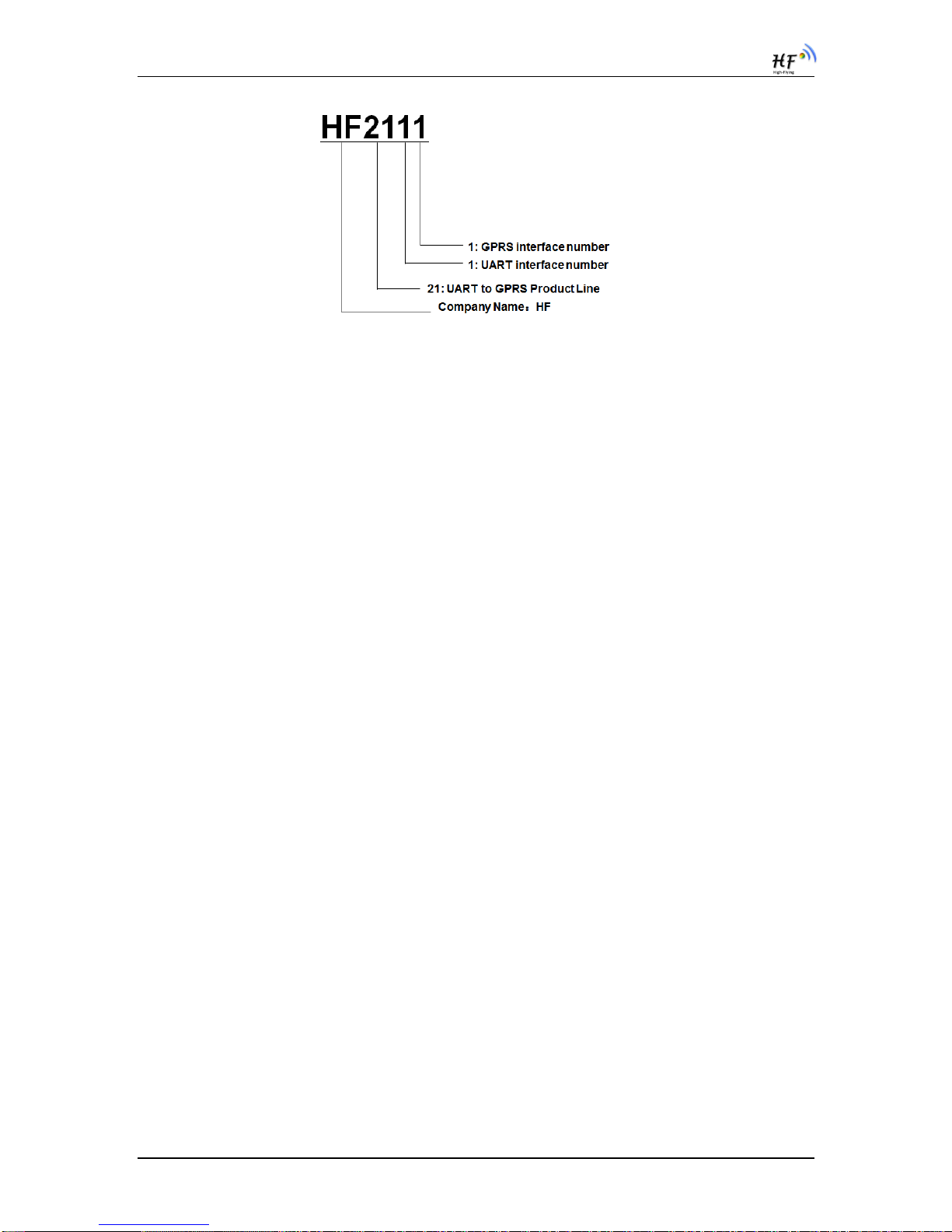
1.2.6. Order Information
Acorrding to customer’s demands,HF2111 product can provide different configured
products,and the particular production code is showed as follow:
HF2111 GPRS Serial Server User Manual
Shanghai High-Flying Electronics TechnologyCo., Ltd 9/29
Figure 4. HF2111 Production Code Definition
1.2.7. Package Information
1 * HF2111
1 * 5V/1A Power Adapter
1 * RS232 Cable
1 * GPRS Antenna
HF2111 GPRS Serial Server User Manual
Shanghai High-Flying Electronics TechnologyCo., Ltd 10/29
2.FUNCTION DESCRIPTION
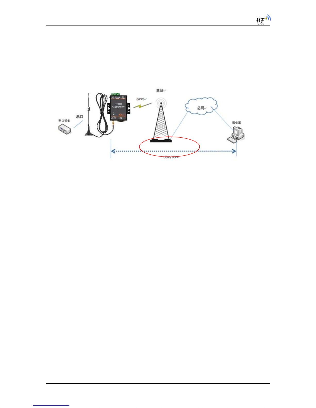
2.1. WirelessNetworking
Product is connected with serial devices and GPRSnetwork and communicatewith
remote server through public network. It is suggested to use build-in TCP/IP protocol
stackto achieve remote control and monitor through UDP/TCPconnection with server.
Figure 5. GPRSwireless network
2.2. Work Mode
2.3.1. Support single and multiple connecton
Single connection: build only one connection (UDP/TCP)
Multiple connection: maximum eight connections (UDP/TCP, AT+SOCKA, AT+SOCKB,
AT+SOCKC)
Note:
Recommendto sendUART data every 1000ms to device, otherwise may lost some
packet.
HF2111 GPRS Serial Server User Manual
Shanghai High-Flying Electronics TechnologyCo., Ltd 11/29
3.IOTSerialTool
3.1. Description
IOTSerialTool is to config the HF-G200/DTU-G101/HF2111 product, it is convenient to config the
product parameters, upgrade firmware via RS232/RS485/RS422 interface.
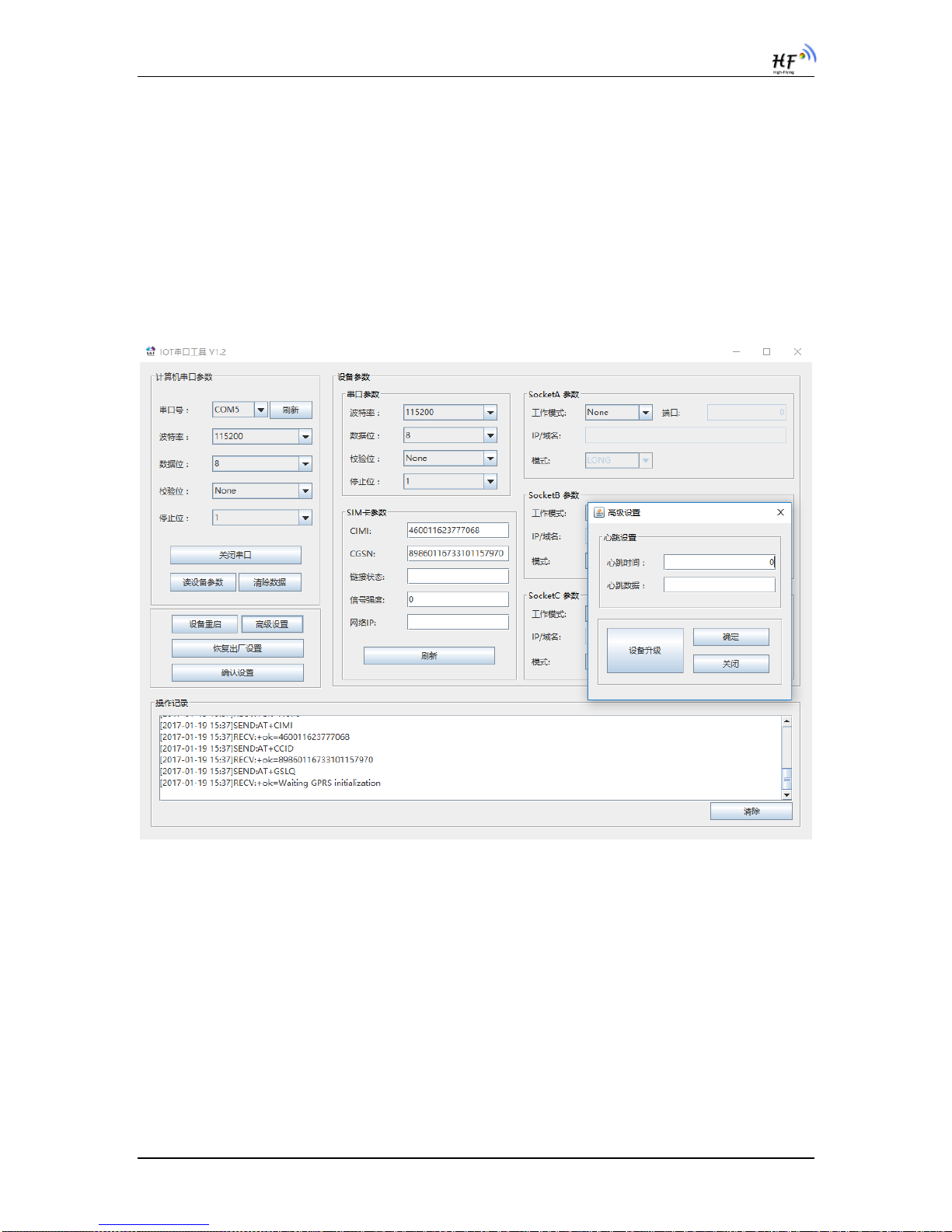
3.2. UI
The following is a note on the interface of this tool in Chinese:
【计算机串口参数】: Computer serial port parameters
【串口号】:Serial number;【刷新】:Refresh;【波特率】:Baud rate;
【数据位】:Data bit;【校验位】:Check bit;【停止位】:Stop bit;
【关闭串口】:Disable serial port;【读设备参数】:Read device parameters;
【清除参数】:Clear parameters;【设备重启】:Device reboot;
【高级设置】:Advanced setting;【恢复出厂设置】:Restore factory settings;
【确认设置】:Confirm setting;【设备参数】:Equipment parameters;
【串口参数】:Serial parameters;【链接状态】:Link state;【信号强度】:signal intensity;
【网络 IP】:Network IP;【sockA 参数】:sockA parameters;【工作模式】:Working mode;
【端口】:port;【IP/域名】:IP/domain name;【模式】:Mode;
【操作记录】:Operation record
HF2111 GPRS Serial Server User Manual
Shanghai High-Flying Electronics TechnologyCo., Ltd 12/29
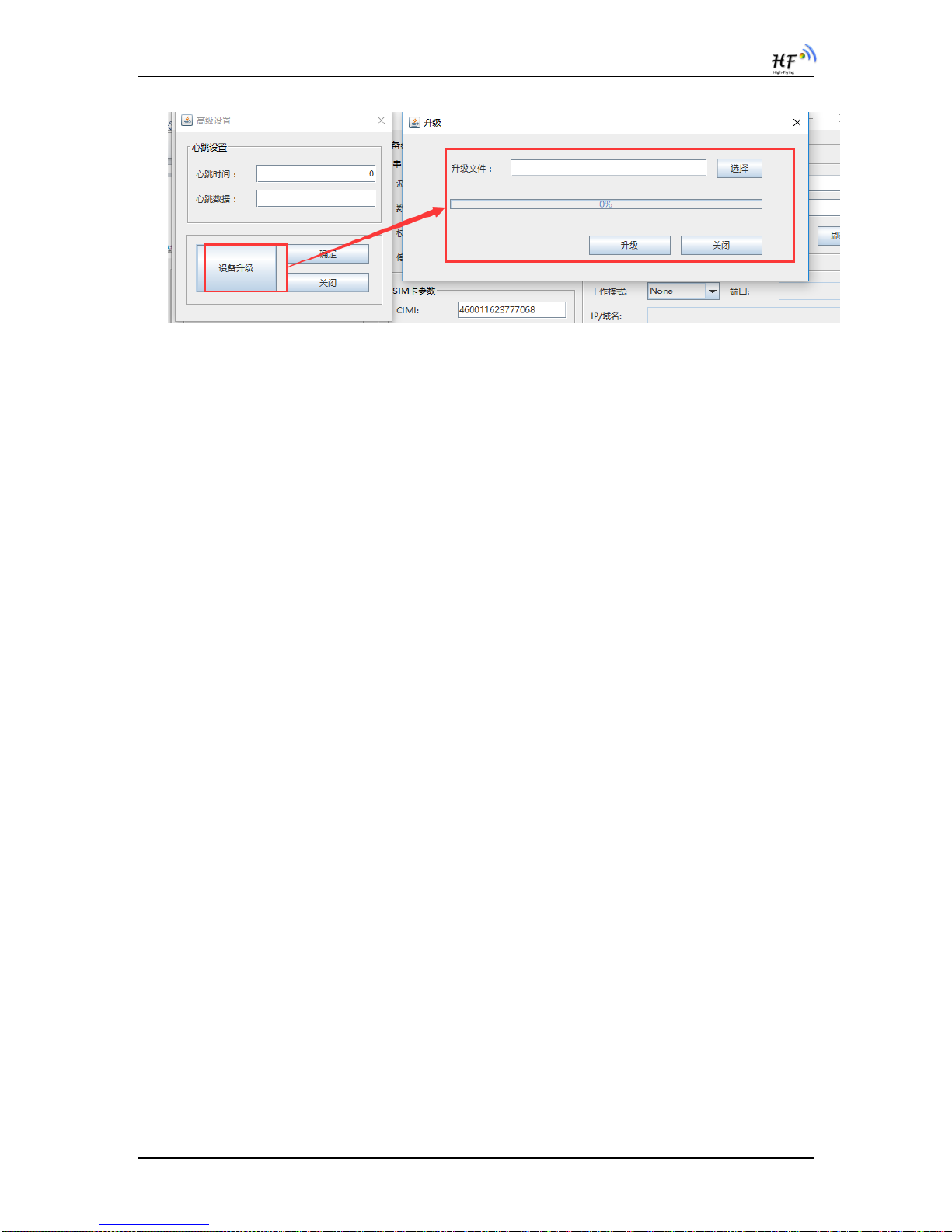
Click Advanced settings to enter heartbeat settings:
【心跳时间】:Heartbeat time;【心跳数据】:Heartbeat data;
【设备升级】:Equipment upgrade;【确定】:confirm;【关闭】:Close;
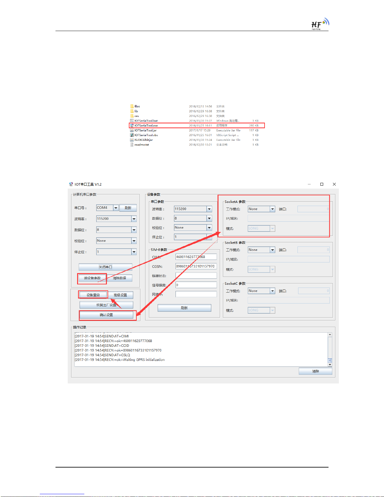
3.3. OperationSteps
a) Click “IOTSerialTool.exe” to open the tool.
b) Set tool serial parameters and click open the serial.(product default parameter is
115200,8,N,1)
c) Click【读设备参数】,in【操作记录】 column, it will show AT command log information
d) Modify the parameter to the needed setting, and reboot to make new setting valid.
e) Click 【高级设置】 can set heart beat and upgrade function.
HF2111 GPRS Serial Server User Manual
Shanghai High-Flying Electronics TechnologyCo., Ltd 13/29

HF2111 GPRS Serial Server User Manual
Shanghai High-Flying Electronics TechnologyCo., Ltd 14/29
4.AT+INSTRUCTION INTRODUCTION
4.1. Configuration Mode
When HF2111 power up, it will default works as transparent transmission mode, then user can
switch to configuration mode by serial port command. HF2111 UART default parameters setting
as below figure,
Figure 6. HF2111 Default UART Port Parameters
In configuration mode, user can setting the product through AT+instruction set, which cover all
web page setting function.
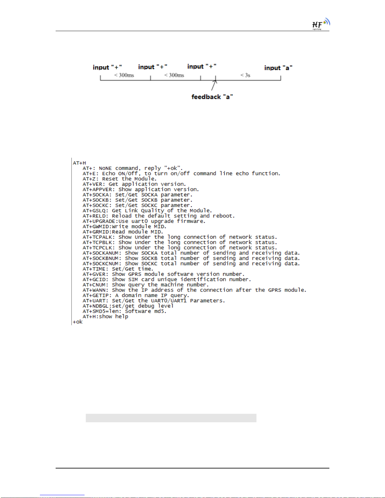
4.1.1. Switch to Configuration Mode
Two steps to finish switching from transparent transmission mode to configuration mode.
UART input “+++”, after product receive “+++”, and feedback “a” as confirmation.
UART input “a”, after product receive “a” and feedback “+ok” to go into
AT+instruction set configuration mode.
Figure 7. Switch to Configuration Mode
Notes:
1. When user input “+++” (No “Enter” key required), the UART port will display feedback
information “a”, and not display input information”+++” as above UART display.
2. Any other input or wrong step to UART port will cause the product still works as original mode
(transparent transmission).
HF2111 GPRS Serial Server User Manual
Shanghai High-Flying Electronics TechnologyCo., Ltd 15/29
3. “+++”and “a”should be input in a certain period of time to make the product switch to
configuration mode. Like the following sequence.
4.2. AT+InstructionSetOverview
User can input AT+Instruction through hyper terminal or other serial debug terminal, also can
program the AT+Instruction to script. User can also input “AT+H” to list all AT+Instruction and
description to start.
Figure 8. ”AT+H” Instruction for Help
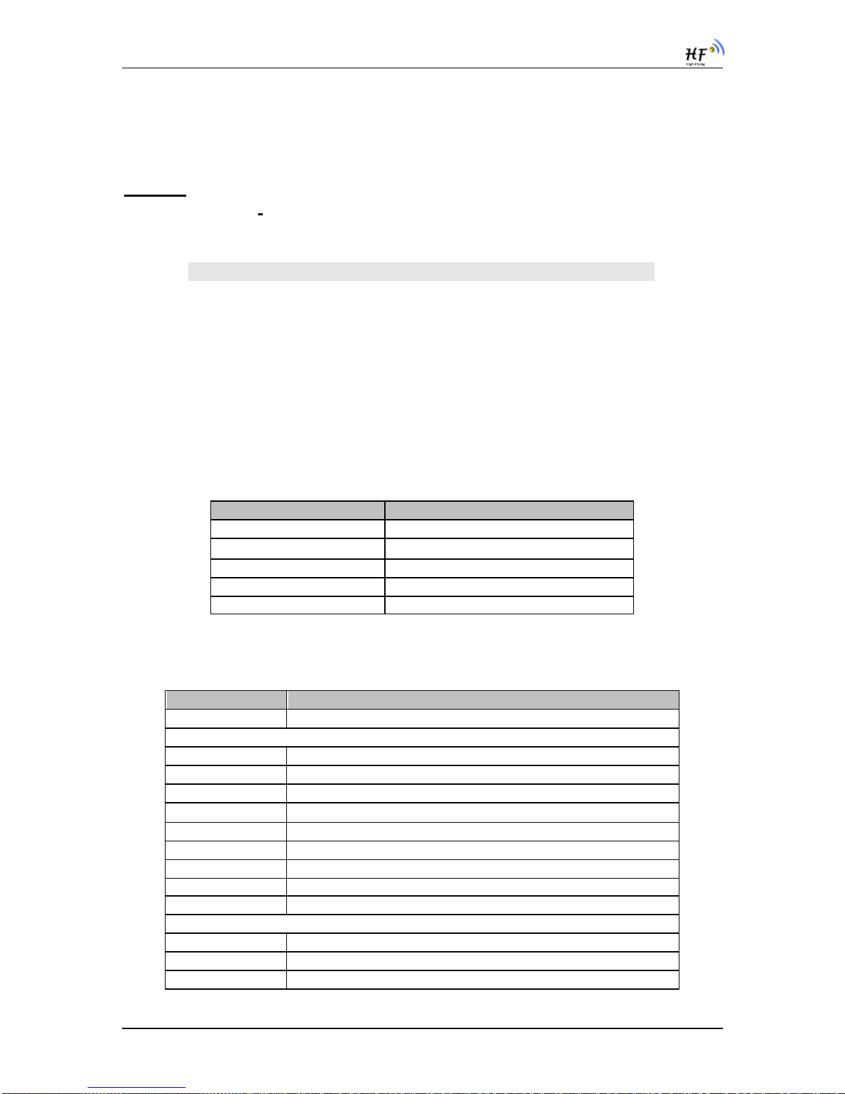
4.2.1. Instruction Syntax Format
4. AT+Instruction protocol is based on the instruction of ASCII commandstyle,the
description of syntax format as follow.
Format Description
< >: Means the parts must be included
[ ]: Means the optional part
Command Message
AT+<CMD>[op][para-1,para-2,para-3,para-4…]<CR>
AT+: Prefix of command message;
CMD: Command string;
[op]: Symbol of command operator,
HF2111 GPRS Serial Server User Manual
Shanghai High-Flying Electronics TechnologyCo., Ltd 16/29
“=” : The command requires parameters input;
“NULL”: Query the current command parameters setting;
[para-n]: Parameters input for setting if required;
<CR>:”Enter” Key, it’s 0x0a or 0x0d in ASCII;
Notes: When input AT+Instruction, “AT+<CMD>” character will display capital letter
automatic and other parts will not change as you input.
Response Message
+<RSP>[op] [para-1,para-2,para-3,para-4…]<CR><LF><CR><LF>
+: Prefix of response message;
RSP: Response string;
“ok” : Success
“ERR”: Failure
[op] : =
[para-n]: Parameters if query command or Error code when error happened;
<CR>: ASCII 0x0d;
<LF>: ASCIII 0x0a;
Error Code
Table5. Error Code Describtion
Error Code
Description
-1
Invalid Command Format
-2
Invalid Command
-3
Invalid Operation Symbol
-4
Invalid Parameter
-5
Operation Not Permitted
4.2.2. AT+Instruction Set
Table6. AT+Instruction Set List
Instruction
Description
<null>
NULL
Managment Instruction Set
E
Open/Close show back function
ENTM
Set product into transparent transmition mode
VER
Query product software version information
APPVER
Query customized software version information
RELD
Restore to factory default setting
Z
Re-start product
CFGTF
Save current setting as factory setting
FCLR
Clear saved factory setting
H
Help
UART Instruction Set
UART
Set/Query serial port parameters
UARTINTERVAL
Set/Query serial port frame time
UARTTYPE
Set/Query serial port type

HF2111 GPRS Serial Server User Manual
Shanghai High-Flying Electronics TechnologyCo., Ltd 17/29
Instruction
Description
UARTHEAD
Set/Query serial port head data
Network Instruction Set
SOCKA
Set/Query SOCK A network protocol parameters
TCPALK
Query if SOCK A TCP link already build-up;
SOCKANUM
Set/Query SOCK A send/receive data bytes.
SOCKB
Set/Query SOCK B network protocol parameters
TCPBLK
Query if SOCK B TCP link already build-up;
SOCKBNUM
Set/Query SOCK B send/receive data bytes.
SOCKC
Set/Query SOCK C network protocol parameters
TCPCLK
Query if SOCK C TCP link already build-up;
SOCKCNUM
Set/Query SOCK C send/receive data bytes.
WANN
Set/Query GPRS network status.
GETIP
Set/Query domain name IP address
HEART
Set/Query heartbeat parameters
LOGIN
Set/Query register data
MODBUSPROT
O
Set/Query Modbus RTU to Modbus TCP function
Upgrade Instruction Set
UPGRADE
Upgrade Firmware
GPRS Instruction Set
GSLQ
Query GPRS signal strength
GVER
Query GPRS chip software version
GCID
Query SIM card CID number
CIMI
Query SIM card IMSI
CGSN
Query device IMEI
GPRS Instruction Set
SCRIPTUART
Upgrade HIS script via UART
MOVESCRIPT
Delete HIS script
4.2.2.1. AT+E
Function: Open/Close show back function;
Format:
Set Operation
AT+E=<status><CR>
+ok<CR><LF><CR><LF>
Parameters:
status: Echo status
on: Open echo
off: Close echo
When HF2111 product firstly switch from transparent transmission to configuration mode, show
back status is open, input “AT+E” to close show back function, input“AT+E” again to open show
back function, use AT+E=on/off command to direct set the echo status..
4.2.2.2. AT+ENTM
Function: Set product into transparent transmition mode;
Format:
AT+ENTM<CR>

HF2111 GPRS Serial Server User Manual
Shanghai High-Flying Electronics TechnologyCo., Ltd 18/29
+ok<CR><LF><CR><LF>
When operate this command, product switch from configuration mode to transparent transmission
mode.
4.2.2.3. AT+VER
Function: Query module software version information;
Format:
Query Operation
AT+VER<CR>
+ok=<ver><CR><LF><CR><LF>
Parameters:
ver: Module software version information;
4.2.2.4. AT+APPVER
Function: Query custmized software version information
Format:
Query Operation
AT+APPVER<CR>
+ok=<ver><CR><LF><CR><LF>
Parameters:
ver: Module custmized software version information;
4.2.2.5. AT+RELD
Function: module restore to factory default setting;
Format:
Set Operation
AT+RELD<CR>
+ok<CR><LF><CR><LF>
When operate this command, module will restore to factory default setting. Support SMS connfig.
4.2.2.6. AT+Z
Function: Restart module;
Format:
AT+Z<CR>
4.2.2.7. AT+CFGTF
Function: Copy User Parameters to Factory Default Parameters;
Format:
AT+CFGTF<CR>
+ok=F-Setting Saved<CR><LF><CR><LF>
Support SMS config.
4.2.2.8. AT+FCLR
Function: Clear saved factory setting
Format:
AT+FCLR<CR>
+ok<CR><LF><CR><LF>
Support SMS config.

HF2111 GPRS Serial Server User Manual
Shanghai High-Flying Electronics TechnologyCo., Ltd 19/29
4.2.2.9. AT+H
Function: Help;
Format:
Query Operation
AT+H<CR>
+ok=<command help><CR><LF><CR><LF>
Parameters:
command help: command introduction;
4.2.2.10. AT+UART
Function: Set/Query serial port parameters. Setting is valid after reset.
Format:
Query Operation
AT+UART<CR>
+ok=<baudrate,data_bits,stop_bit,parity,flowctrl><CR><LF><CR><LF>
Set Operation
AT+UART=<baudrate,data_bits,stop_bit,parity,flowctrl><CR>
+ok<CR><LF><CR><LF>
Parameters:
baudrate:
1200,1800,2400,4800,9600,19200,38400,57600,115200
data_bits:
8
stop_bits:
1,2
parity:
NONE
EVEN
ODD
Flowctrl: (CTSRTS),
NFC: No hardware flow control
FC: hardware flow control
Support SMS config.
4.2.2.11. AT+UARTINTERVAL
Function: Set/Query serial port frame time. Setting is valid after reset.
Format:
Query Operation
AT+UARTINTERVAL<CR>
+ok=<interval><CR><LF><CR><LF>
Set Operation
AT+UARTINTERVAL=<interval><CR>
+ok<CR><LF><CR><LF>
Parameters:
interval: UART frame time.
default 200ms
4.2.2.12. AT+UARTTYPE
Function: Set/Query serial port type. Setting is valid after reset. Only valid for
HF-G200 and HF2111 product.
Format:
Query Operation

HF2111 GPRS Serial Server User Manual
Shanghai High-Flying Electronics TechnologyCo., Ltd 20/29
AT+UARTTYPE<CR>
+ok=<type><CR><LF><CR><LF>
Set Operation
AT+UARTTYPE=<type><CR>
+ok<CR><LF><CR><LF>
Parameters:
type: UART type
RS485: UART type is RS485, half-duplex.
RS232: UART type is RS232/RS422, full-duplex.
4.2.2.13. AT+USERHEAD
Function: Set/Query adding head data for each serial data. Setting is valid after
reset. Only valid for HF-G200 and HF2111 product.
Format:
Query Operation
AT+USERHEAD<CR>
+ok=<data_len><data><CR>< LF ><CR>< LF >
+ok=None<CR><LF ><CR><LF >
Set Operation
AT+USERHEAD=None<type><CR>
AT+USERHEAD=<data_len><data><type><CR>
+ok=None<CR><LF ><CR><LF >
+ok=<data_len><data><CR>< LF ><CR>< LF >
Parameters:
data_len: head data length
data:head data, if need hex format add blank character. Ex: [68 79 90]
Support SMS config.
4.2.2.14. AT+SOCKA
Function: Set/Query SOCK A network protocol parameters, Setting is valid after
reset. Support SMS config.
Format:
Query Operation
AT+SOCKA<CR>
+ok=<protocol,port,IP,mode><CR><LF><CR><LF>
Set Operation
AT+SOCKA=<protocol,port,IP,mode><CR>
+ok<CR><LF><CR><LF>
Parameters:
protocol:
NONE: none setting, clear current setting.
TCP
UDP
port: protocol port ID: Decimal digit and less than 65535
IP: Server’s IP address or domain name
mode: Connectiontype
LONG: long link connection
SHORT: short link connection.
4.2.2.15. AT+SOCKB
Function: Set/Query SOCK B network protocol parameters, Setting is valid after
reset. Support SMS config.
Format:
Table of contents
Other Hi-flying Server manuals


