Hi-Link HLK-LD1115H-24G User manual

Human Presence Sensor Radar
HLK-LD1115H-24G User Manual
V1.2
2021-12-6
Due to product upgrades or other reasons, the content of this document will be
updated. This document is intended as a guide only and neither the information nor
the recommendations stated shall constitute any express or implied warranty.

2
Content
1. Product Overviews..................................................................................................................2
2. Module appearance and interface...........................................................................................3
3. Module performance...............................................................................................................4
4. Debug wiring.......................................................................................................................... 5
5. Debug configuration............................................................................................................... 5
6. Radar installation and testing................................................................................................. 9
7. Precautions............................................................................................................................14
8. Appendix...............................................................................................................................15

3
1. Product Overviews
HLK-LD1115H-24G is a high sensitivity 24GHz millimeter wave human presence detection
radar module. Different from the traditional radar, which judges the existence of the human body by
detecting the large-scale movements of the human body or the small-scale body movements, the
main feature of this module is that on the basis of the function of the traditional human-body
induction radar, it also has the ability to detect and accumulate small-scale movements such as
human respiration. , to determine the function of the existence of the human body. Therefore,
compared with traditional Doppler radar, it has presence detection within a certain range, with higher
accuracy, and is not easy to miss reports.
Modules can penetrate non-metallic enclosures without openings. Common materials include plastic, glass,
wood, ceramic, and more. Especially for human presence detection applications, wall-mounted plastic 86-
box panels and ceiling-mounted ceiling buckle enclosures are recommended.
4
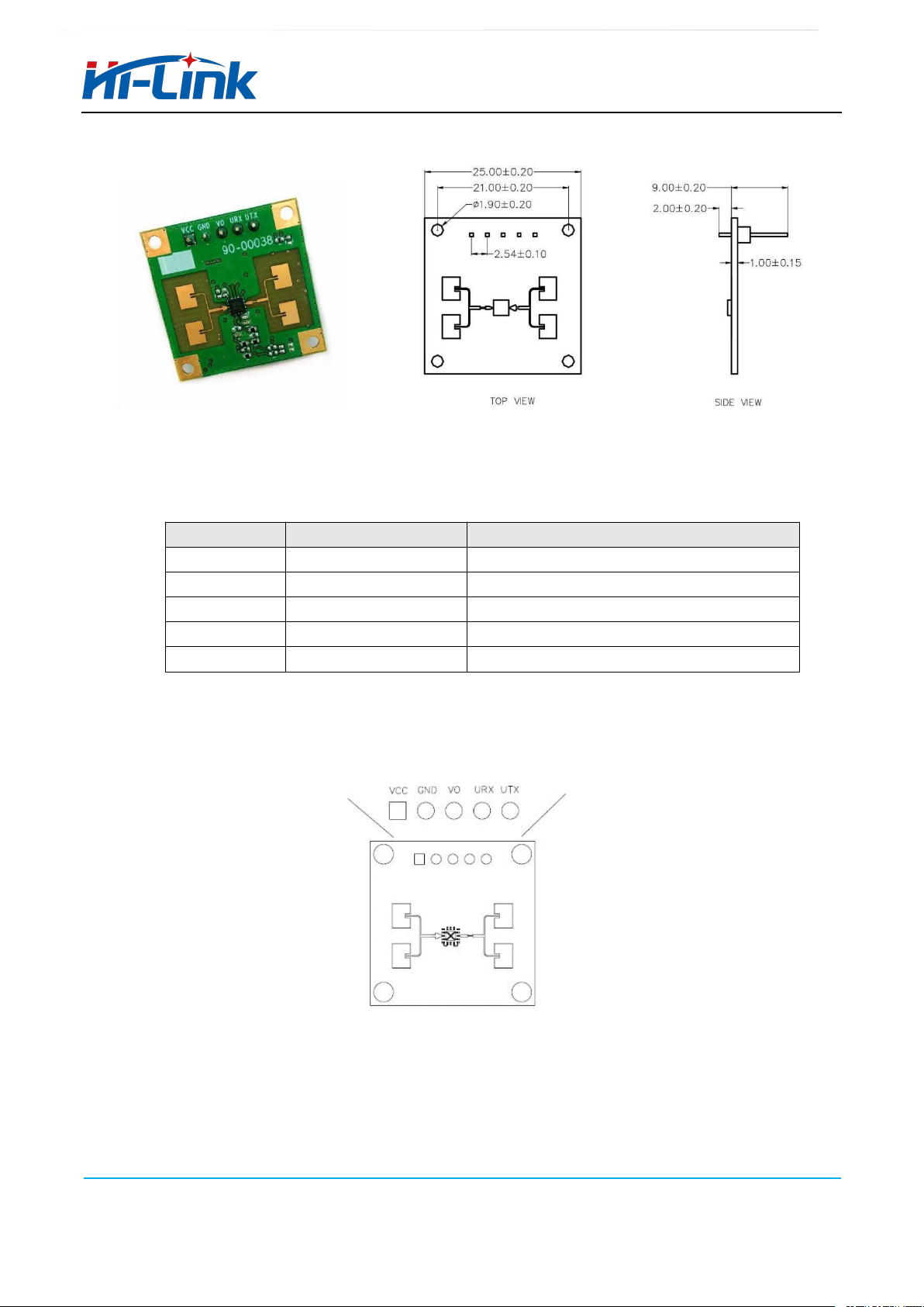
2. Module appearance and interface
Pin interface definition:(2.54mm pitch pinheader connector isrecommended for the interface)
Pin
Name
Remark
1
VCC
Vlotage 5V power supply
2
GND
Ground
3
VO
Induction output pin (optional)
4
URX
TTL serial receive
5
UTX
TTL serial transmission

5
24G-24.25GHz
Frequency
Typical value
Parameter
Voltage 3.6-5V
Current
70mA
Output serial
level
3.3V
Detection cycle
Adaptive
Vertical
Horizontal
3. Module performance
Modulation CW
Detection distance >4m Static human presence detection,>16m motion detection
Scope The hanging height is 3m, the static body detection coverage radius is 2m, and
the mobile detection radius is >5m
Data Format Serial ASCII output/or high and low level
Start Time About 15 s
Antenna half power angle Horizontal ±57°, vertical ±24° (see the figure below for the definition of the
horizontal/vertical direction of the antenna)
6
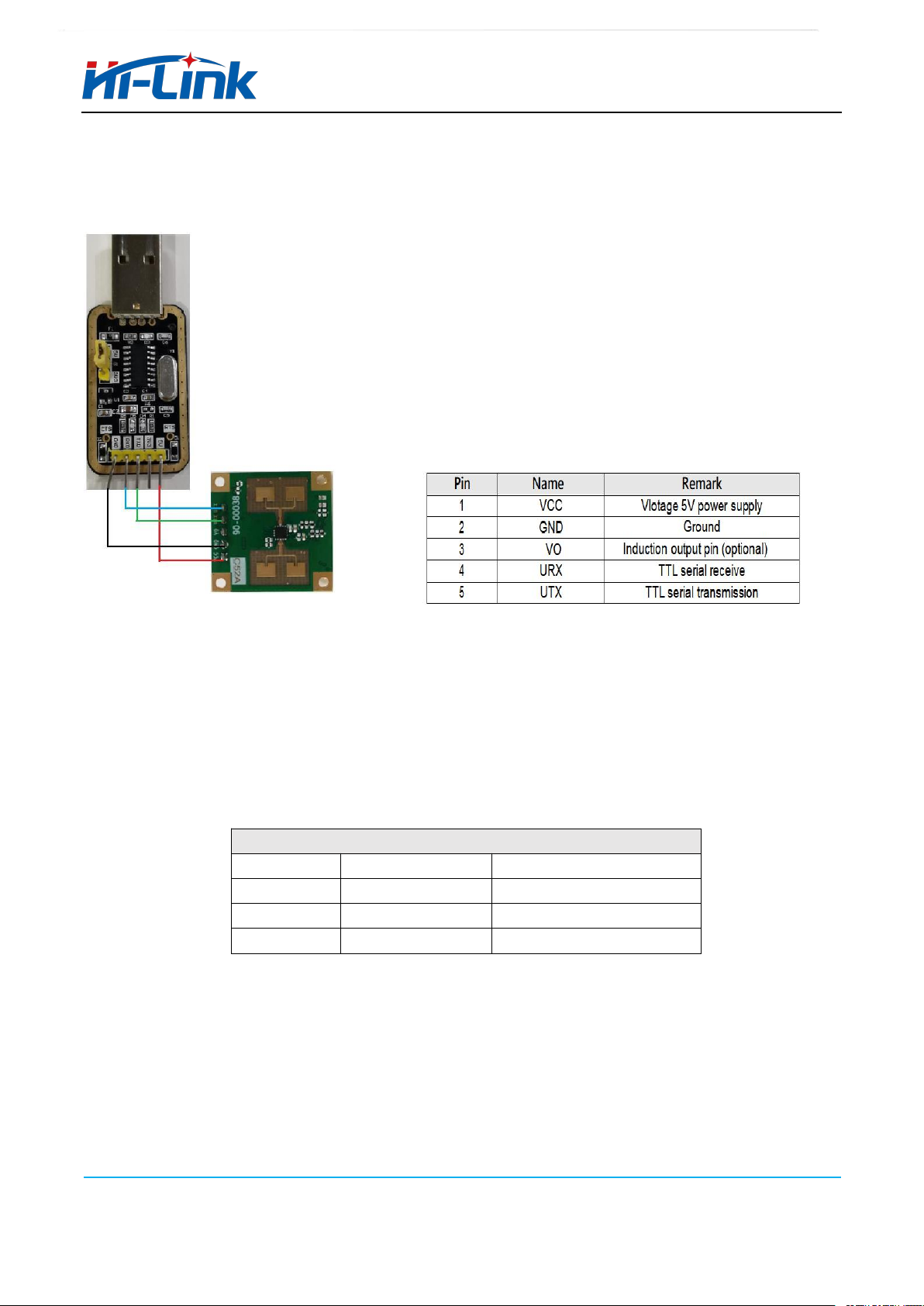
4. Debug wiring
HLK-LD1115H-2.4G uses the serial port to output the test results in string format, so when
users test the module, they can first perform a quick test evaluation on the serial port assistant.
The module and serial board can be connected according to the figure
on the left:
Module1 pin is connected to the serialboard 5V
Module2 pin is connected to the serial board GND
Module4 pin is connected to the serial board TX
Module5 pin is connected to the serial board RX
(There is a silk screen on the pins of the radar module, which can be
directly connected)
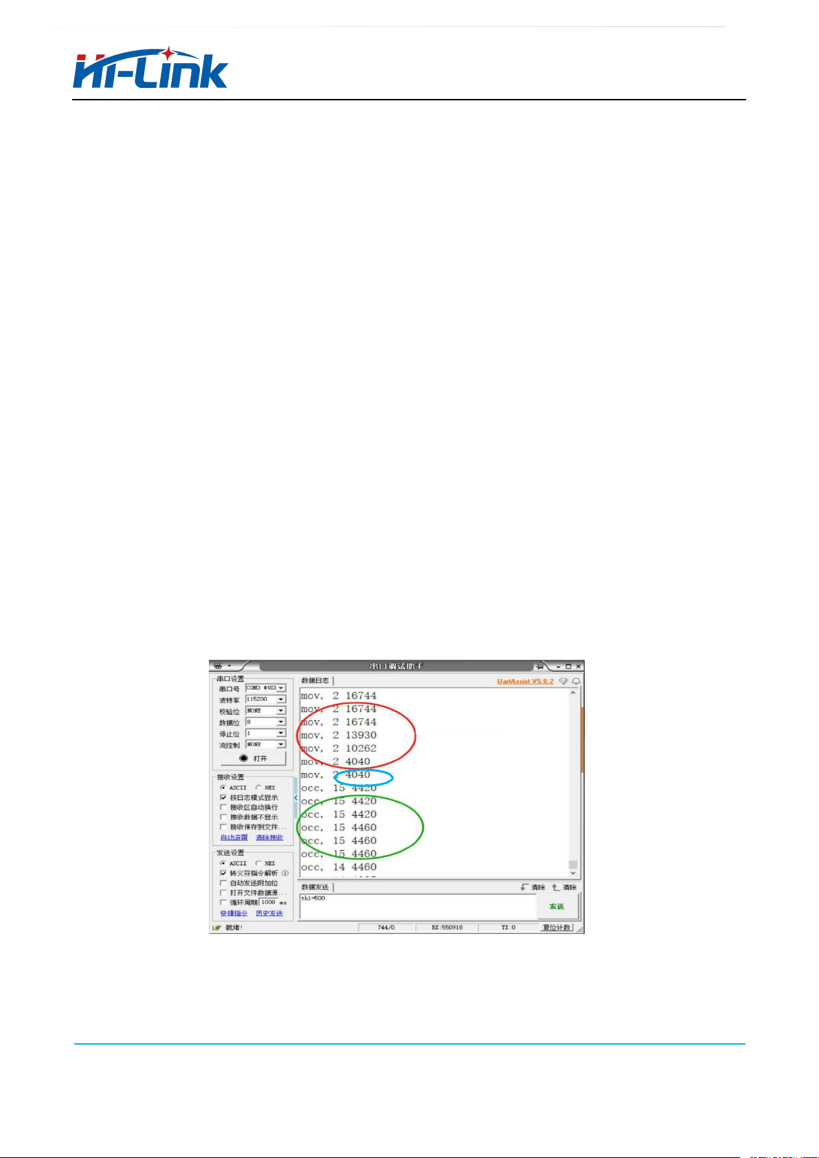
5. Debug configuration
You can debug and test on the computer through the serial port assistant HLK-LD1115H-24G.
Use any serial debugging tool. The baud rate is 115200, 8 data bits, 1 stop bit, check bit and flow control
are None, select ASCII for receive settings, and select ASCII for send settings.
Product supports UART text protocol
1
Baud rate
115200
2
Word width
8bit
3
Stop bit
1
4
Parity
None
7
The first number represents the
spectral line position,the second
number represents the signal
strength
Configuration directives
th1=**, set the motion detection sensitivity. Integer setting. The default configuration is th1=120. The higher
the value, the less sensitive the module is. The sensing distance and range are smaller. The FOV under the reference
sensitivity setting is given later.
th2=**,set the presence detection sensitivity. Integer setting. The default configuration is th2=250. The higher the value,
the less sensitive the module is to presence detection. The sensing distance and range are smaller. The FOV at the reference
sensitivity setting is given later. Generally, the sensitivity can not be adjusted.
dtime=**, set the GPIO delay detection time. Integer setting. The default configuration is dtime=5. A value of 5
is 5S.
mov_sn=**, set the GPIO to pull up the GPIO when it detects several large-scale data. The default
configuration is mov_sn=3, the larger the setting, the less sensitive it is, and it can be increased when there are large
false positives.
occ_sn=**, set how many times small amplitude data is detected after GPIO is pulled high to maintain GPIO
high level. The default configuration is occ_sn=5, the larger the setting, the less sensitive it is. It is not recommended
to increase it.
save, save the parameter settings. If save is not sent, the power-down will fail.
get_all, the module outputs the current parameter settings.
All commands sent with carriage return and line feed are valid.
Radar output
When the radar detects a larger motion, it outputs mov, ******. (The second number represents the signal strength)
When the radar detects the static state of the human body or small amplitude movements, it will output occ, ******. (The
second number represents the signal strength)
When the radar cannot detect the target, it stops outputting. The user can make a certain delay in the upper layer to
avoid frequent unmanned state when the signal is weak. (The first number represents the spectral line position, the
user can ignore it directly)
Note: The startup time of the module is about 15 seconds, and it starts to output data after 15 seconds of
power-on. Because the module makes existence judgment by accumulating signal characteristics for a period
of time, when the person disappears from the radar detection range, the radar will continue to accumulate
signals for a period of time, so the radar will stop outputting after a period of lag time.
Motion status output
Static state output
8
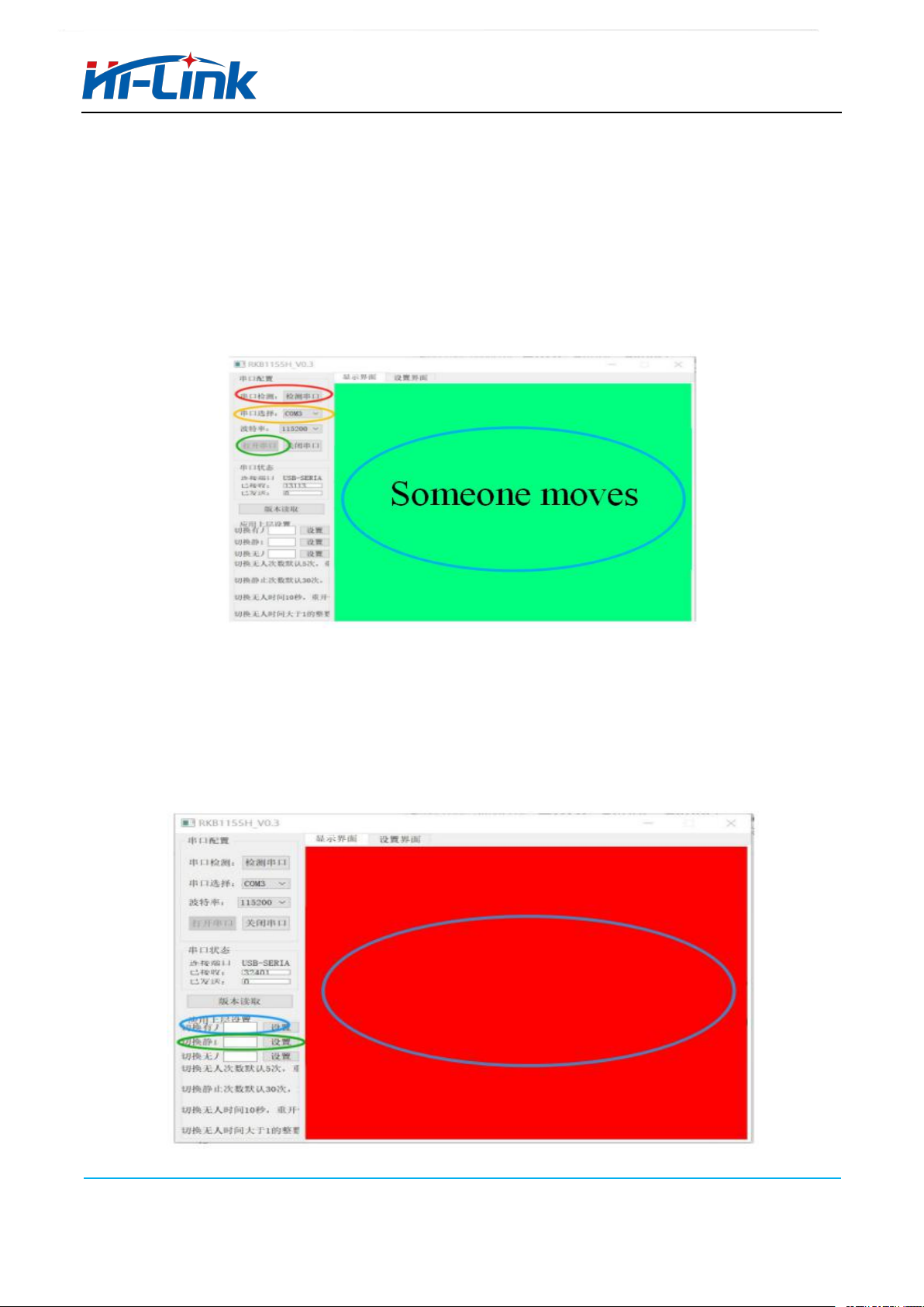
Using the host computer
We provide a matching host computer for users to use for evaluation. Different from the direct
observation of the module output through the serial port, the host computer can do some upper-layer
delay processing after receiving the serial port signal output by the module.
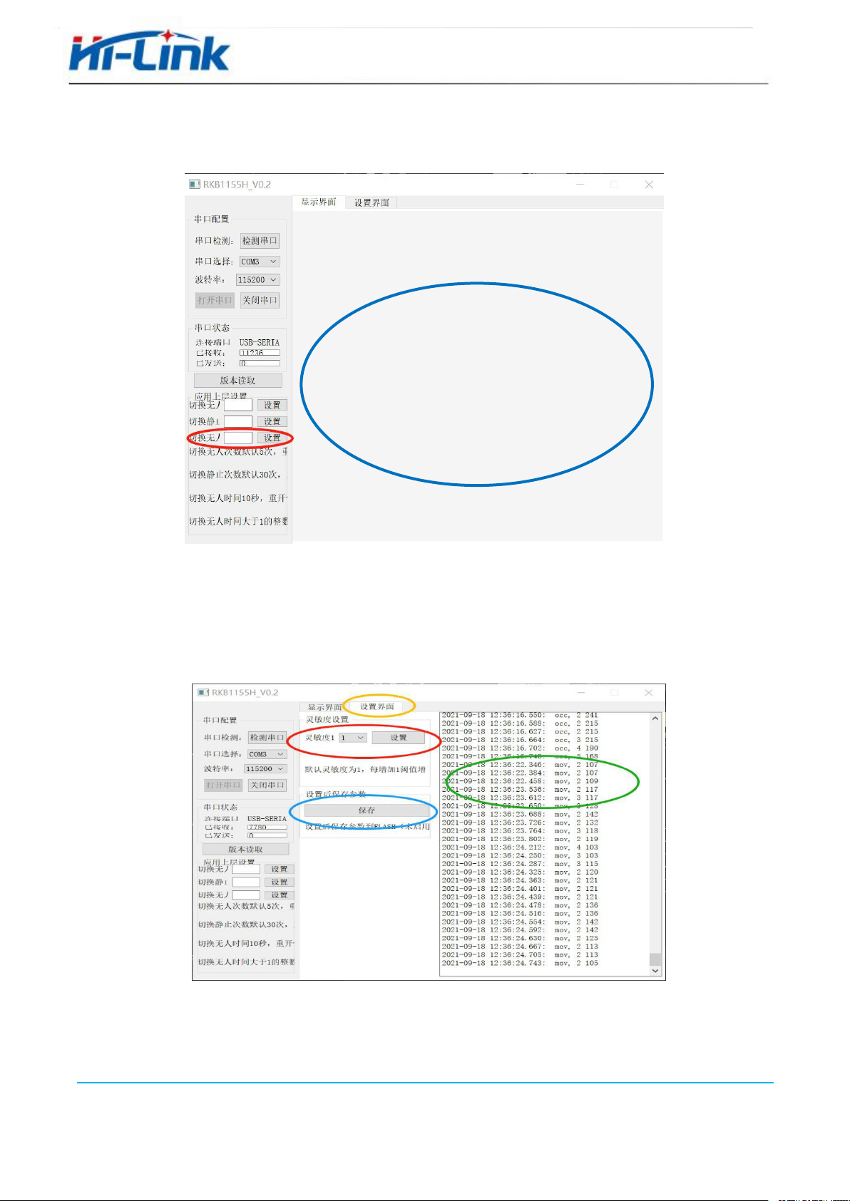
After connecting the module, click the serial port detection -serial port selection -open the
serial port, and the display interface will display the current status. Someone moves the
corresponding module serial port mov output.
Enter an integer greater than 1 in the switch static window. When the number of times the
host computer receives occ continuously is greater than the set value, the host computer
displays that someone is in a static state, corresponding to the occ output of the module serial
port. Enter an integer greater than 1 in the switch man status window. When the host
computer enters the man static state, when the number of consecutive move received is greater
than the set value, the host computer displays that there is someone moving.
Somenone static
9
Enter an integer greater than 1 in Toggle Unattended Window, the window unit is seconds.
When the upper computer does not receive any signal longer than the set time, the upper
computer displays the unmanned state.
Click the setting interface, and the sensitivity setting and saving parameters window will
appear. The Sensitivity drop-down menu can select 1-30, 1 is the default sensitivity setting,
and each increase by 1 increases the sensitivity threshold th1/th2 by 10%. The module does
not support flash save temporarily, and the save button of the host computer can be ignored.
Parameters such as sensitivity need to be reconfigured after power failure. The right side of
the window will also display the output signal of the module's serial port.
Note: When performing the setting operation of each window in the upper computer, you need to
click the button to close the serial port of the upper computer. After setting, click to open the
serial port.
Unmanned
10
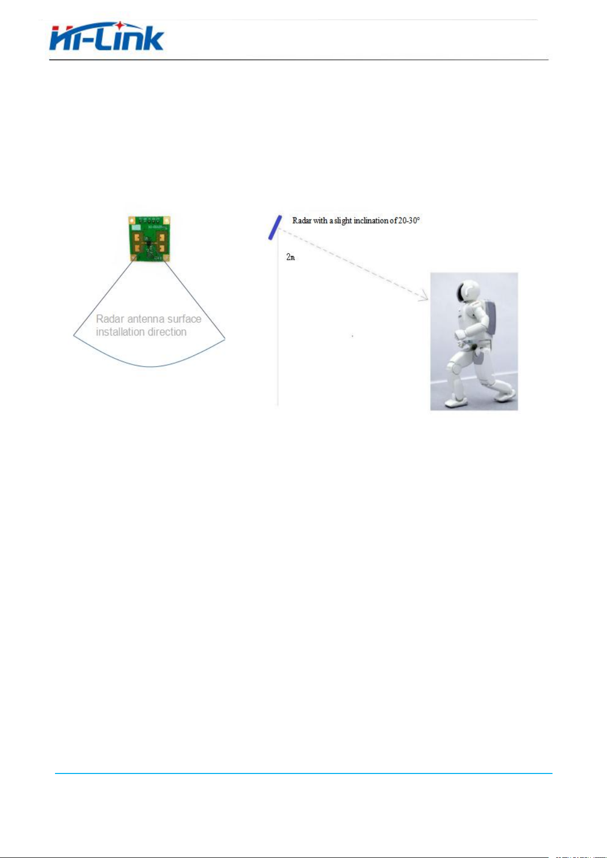
6. Radar installation and testing
Test Application Scenario 1: Wall Mounting Linear Test
The installation height is 2 meters, and the human body is facing the radar when measuring. Test coverage in
both standing and walking states. (There will be a test environment display in the appendix)
Reference coverage
The figure below shows the radar coverage for stationary standing (orange area) and
motion (blue area). for reference. (The left and right range of the blue motion detection is
limited by the test site, and only 4.5 meters on the left and right can be measured. The actual
coverage may be larger. For details, please refer to the Appendix Test Environment
Reference sensitivity configuration 1:
th1=120 (corresponding to motion detection sensitivity)
th2=250 (corresponding to presence detection sensitivity)

11
m
20
18
16
14
Mobile
detection
area
12
10
8
6
4
Static Presence
Detection Zone
2
-6
-4
-2
0
Radar
2
4
6

12
0
Radar
m
20
18
16
14
12
10
Mobile
detection
area
8
6
4
Static Presence
Detection Zone
2
0
-6
-4
-2
2
4
6
Reference sensitivity configuration 2:
th1=500 (corresponding to motion detection sensitivity)
th2=250 (corresponding to presence detection sensitivity)
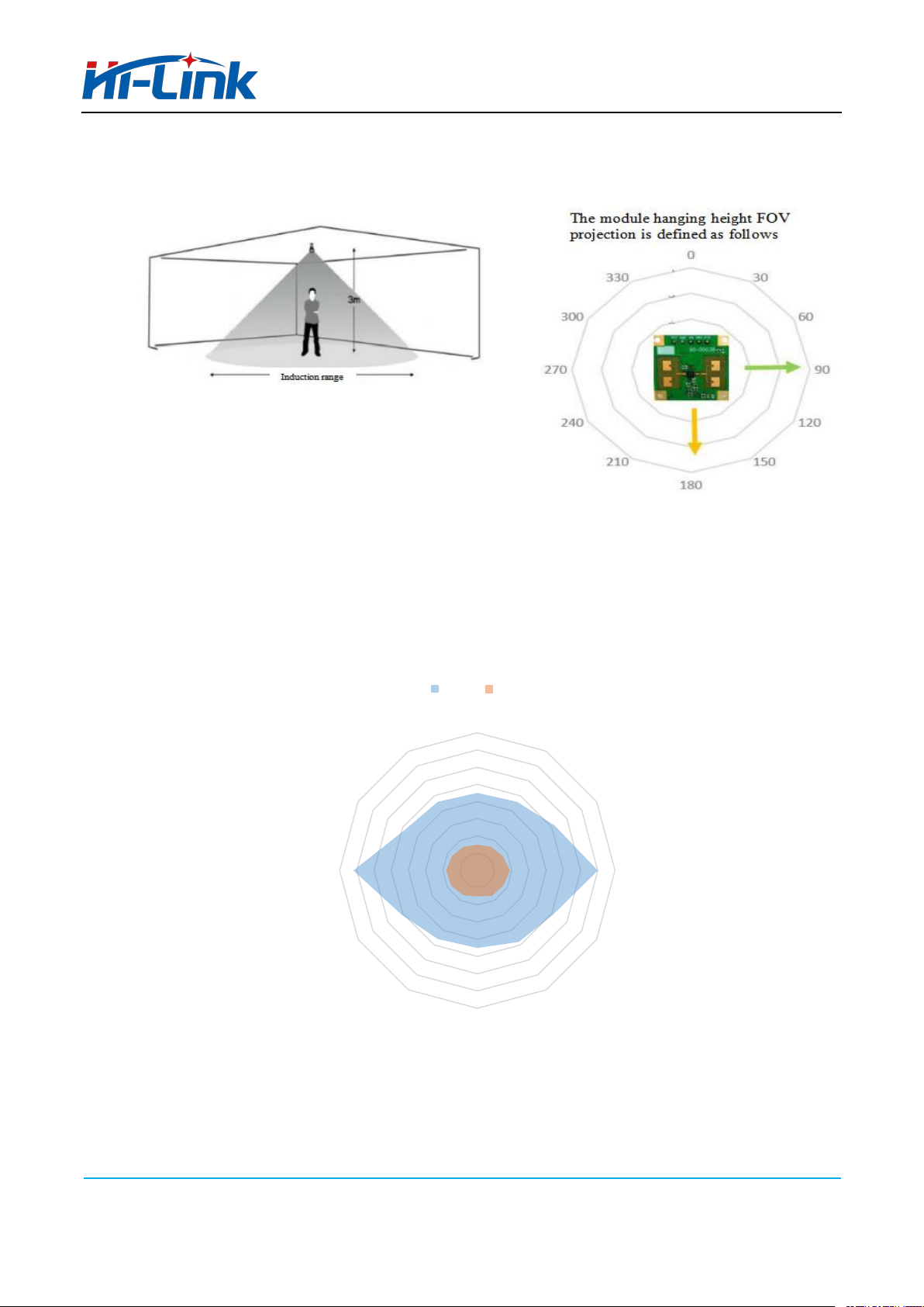
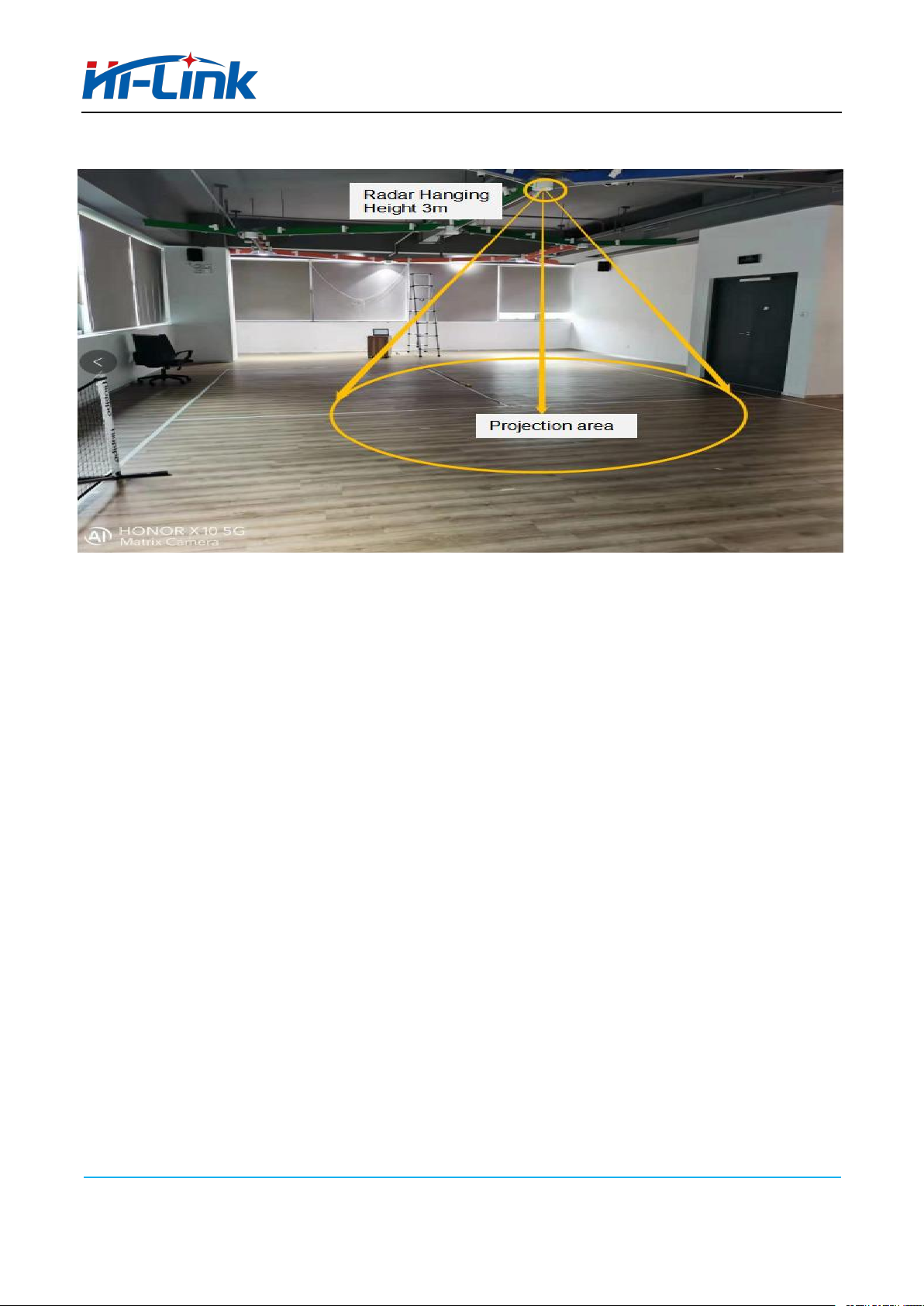
Test Application Scenario 2: Hanging Height Vertical Test
This module can also be hung up for human presence detection. Our test scenario is to hang at a height of 3
meters and measure the FOV of the human body sitting still (orange area) and moving state (blue area).
(There will be a test environment display in the appendix)
13
00
Reference sensitivity configuration 1:
th1=120 (corresponding to motion detection sensitivity)
th2=250 (corresponding to presence detection sensitivity)
Hanging Height FOV
Moving Static
0
8
330 730
6
5
300 460
3
2
1
270 090
240 120
210 150
180
Reference sensitivity configuration 2:
th1=200 (corresponding to motion detection sensitivity)
th2=250 (corresponding to presence detection sensitivity)

14
Moving Static
0
330
300
0
8
7
6
5
4
3
2
1
0
90
120
210
150
0
330
300
8
7
6
5
4
3
2
1
0
60
270
90
240
120
210
150
180
0
Hanging Height FOV
27
180
Reference sensitivity configuration 3:
th1=300 (corresponding to motion detection sensitivity)
th2=250 (corresponding to presence detection sensitivity)
Hanging Height FOV
Moving Static
240
60
30
30

15
7. Precautions
During installation, avoid metal and other objects blocking the transmission of electromagnetic waves in
front of the module to block the antenna.
Different housing materials and the distance between the module and the inner surface of the housing will
result in different spectral energy returned and parameter settings, which need to be fine-tuned according
to actual conditions. It is generally recommended that the module be 5-6mm away from the housing,
which can be adjusted according to the actual measurement.
We recommend users to test according to the default settings of the module. If the effect is not as
expected, you can send the shell structure to the original factory, and the original factory will test
and adjust a reference setting.
It is recommended to use plastic as the casing, because the radar is a very sensitive module in the
presence of the human body. If the casing is made of a material with large attenuation, it may
affect the detection.
If the person under test sits quietly with his back to the radar, the sensing effect will decrease. The
rise and fall of the chest or abdomen caused by breathing cannot be detected when the back is
facing the radar.
Install to avoid the air outlet of the air conditioner, fans and other objects. Shaking equipment and
objects may be detected by radar to determine the presence of persons.
When multiple modules are installed and used at the same time, the distance between the modules should
be greater than 0.5 meters, and the antennas of different modules should not face each other.
According to user scenarios, the sensitivity is adjustable. Users can adjust the sensitivity according
to their actual application scenarios. The sensitivity settings given in this manual can be used for
users' reference. The FOV given in the manual is only for our test environment, and the actual FOV
may deviate due to different actual scene environments or factors such as housing.
If you need more technical support, you can contact sales.

16
8. Appendix
Module test environment display
1. Wall hanging test:
17
2. Hanging height installation test:
Appendix:
about power supply
■An isolated power supply must be used. At the same time, the AC rectifier bridge and transformer
should avoid direct contact with the module, and try not to make the transformer and rectifier face
the module. The shielding layer can be staggered or added.
■The power supply ripple should be less than 50mV as far as possible to avoid spikes in the power supply.
■Do not add devices such as anti-reverse diodes in the DC power supply chain. Adding any device
to the DC power supply chain will increase the power supply noise and cause false alarms.
■The power drive current should not be less than the normal operating current of the module.
Table of contents
Other Hi-Link Radar manuals

Popular Radar manuals by other brands

Simrad
Simrad argus Installation and service manual

Rosemount
Rosemount 5600 Series Reference manual

Parametric
Parametric PCR2-EU868-ODA quick start guide

FLIR
FLIR Raymarine Quantum Q24C installation instructions

Kustom Signals
Kustom Signals DRU III Operator's manual

Radarsign
Radarsign TC-800 installation manual

kymati
kymati KY-LOC 1D.02.01 user manual

Uniden
Uniden R9 quick start guide

Sports Radar
Sports Radar Tracer Pro instruction manual

Infineon
Infineon XENSIV BGT60TR13C user guide

Bindicator
Bindicator F78MP Series Installation & operation manual

Endress+Hauser
Endress+Hauser Micropilot M FMR240 operating instructions


