Infineon XENSIV BGT60TR13C User manual

Please read the Important Notice and Warnings at the end of this document
www.infineon.com page 1 of 20 2022-05-16
XENSIV™60GHz BGT60TR13C Radar System on
Module MCU4 Presence Detection
User guide
About this document
Scope and purpose
This document is a user guide for the presence detection software qualified on the XENSIV™60GHz
BGT60TR13C system-on-module (SoM) MCU4 board as a reference hardware platform.
Intended audience
Customers interested in using the Infineon XENSIV™60GHz BGT60TR13C SoM solution for presence detection
in various consumer applications.

2 of 20
2022-05-16
XENSIV™60GHz BGT60TR13C Radar System on Module MCU4
Presence Detection
Introduction
Table of contents
About this document....................................................................................................................... 1
Table of contents............................................................................................................................ 2
1 Introduction .......................................................................................................................... 3
1.1 What is radar for presence detection?....................................................................................................3
1.2 Key benefits .............................................................................................................................................3
2 Prerequisites ......................................................................................................................... 4
2.1 Hardware .................................................................................................................................................4
2.2 Software...................................................................................................................................................5
3 Module configuration software setup ....................................................................................... 6
4 Set and get configuration........................................................................................................ 7
5 Presence event output...........................................................................................................11
6 Macro and micro threshold tuning...........................................................................................12
6.1 Reading the macro and micro level......................................................................................................12
6.2 Increase Sensitivity by parameter adjustment ....................................................................................13
7 Signal verification mode ........................................................................................................14
7.1 Measurement setup...............................................................................................................................15
8 Anti-interference ..................................................................................................................16
9 Firmware update ..................................................................................................................17
10 Additional documents............................................................................................................18
Revision history.............................................................................................................................19

3 of 20
2022-05-16
XENSIV™60GHz BGT60TR13C Radar System on Module MCU4
Presence Detection
Introduction
1 Introduction
The Infineon radar presence detection solution detects both macro- and micro-movements in a configurable
range using the XENSIV™60GHz BGT60TR13C radar sensor. This user guide for the Infineon radar presence
detection solution describes the required software and hardware, and how to set up and use the module
configuration software to configure and update the system. In an accompanying mounting recommendations
guide, the user can see how to mount the presence solution in indoor environments. Additional user guides are
available and are listed at the end of this document.
1.1 What is radar for presence detection?
Motion sensing is a standard feature in many devices. Today’s devices become smarter by knowing if the user is
around or not. Traditionally motion sensors have been designed using passive infrared (PIR) sensing. As simple
as PIR is, there are performance limitations. For example, PIR sensors cannot detect micro movements. In
addition, they require a lens, while radar sensors can be covered and disguised behind plastic enclosures.
What if there were a solution that could detect the tiniest movements without requiring an opening in the
product housing?
Infineon’s radar presence detection solution enables the detection of human presence within a configured
range. Enabled by our XENSIV™60 GHz BGT60TR13C radar with its sophisticated radar presence detection
algorithms, this solution provides extremely high accuracy in detecting both macro and micro movements.
1.2 Key benefits
Ready-to-use radar solution for presence sensing with adjustable detection range
Ability to detect micro-movements
Radar sensor immune to environmental factors such as temperature, wind, sunlight and dust/debris
A fully tested and verified solution for presence sensing for home, office and commercial buildings

4 of 20
2022-05-16
XENSIV™60GHz BGT60TR13C Radar System on Module MCU4
Presence Detection
Prerequisites
2 Prerequisites
2.1 Hardware
Figure 1 Reference hardware platform – XENSIV™60 GHz BGT60TR13C SoM board (mounted on
motherboard for development/evaluation purposes)
The module can be connected with a UART serial interface (baud rate 115200, 8N1) for command
communication. There is a converter chip on the motherboard to convert the UART interface to USB for PC
connection. Set the dip switch as follows to enable USB_UART connection.
Figure 2 USB_UART selection
The user must download and install the driver at the following link to ensure the USB- to- UART converter chip
can work at on a PC.
https://www.cypress.com/documentation/software-and-drivers/microsoft-certified-usb-uart-driver

5 of 20
2022-05-16
XENSIV™60GHz BGT60TR13C Radar System on Module MCU4
Presence Detection
Prerequisites
The following dip switch setting can directly route the USB connection to the module. The module will then
become a USB device, acting as VCOM at the PC.
USB_MCU selection
2.2 Software
Infineon_ XENSIV™60 GHz BGT60TR13C SoM _Presence_v1.3.0_build-xxxxxxx.zip is part of the above software
release package.
This archive contains the following files after extraction to the folder MCU4_SoM:
IFX_B XENSIVTM 60GHz BGT60TR13C SoM _MCU4_Module_Config_v1.3.1_build-xxxxxxx.exe
IFX_ XENSIVTM 60GHz BGT60TR13C SoM _MCU4_Presence_v1.3.0_build-xxxxxxx.bin
The “xxxxxxx” stands for the build and version number of the firmware and should match the number in the
archive filename.

6 of 20
2022-05-16
XENSIV™60GHz BGT60TR13C Radar System on Module MCU4
Presence Detection
Module config
uration software setup
3 Module configuration software setup
Connect the radar board to the PC through USB, and open the file “IFX_ XENSIVTM BGT60TR13C SoM
_MCU4_Module_Config.exe”. Select the correct comport number (COM8 in this example) and press “Connect”.
Figure 4 Com port selection
If the board is connected successfully, a firmware version will show in the box. Otherwise a fail message will be
shown at the bottom.
Figure 5 Firmware version get success

7 of 20
2022-05-16
XENSIV™60GHz BGT60TR13C Radar System on Module MCU4
Presence Detection
Set and get configuration
4 Set and get configuration
The user can set or get the configuration of the radar under the “Parameter” tab. The following items are
currently available:
Item
Description
Version
Get
the firmware version in MCU.
Max
.
range
[0.66 to 10.2]
Get or set the maximum detection distance for presence detection.
The setting would be stored in Flash; default is 1.00 m.
Sensitivity
Get or set the sensitivity level presence detection; higher
sensitivity
means more sensitivity to small movements. Changing the sensitivity
would change the macro and micro threshold values. “Max”
sensitivity is a special setting that will extend the observation time to
10 s, which means the response of changing from presence to
absence will have a delay of 10 s. The setting would be stored in
Flash; default is high.
Note: The user is recommended to use a “max” sensitivity setting for
optimal performance at angles and for use cases such as a person
sitting on a chair behind a table.
Event control
Enable/disable active output command of presence or absence event
change. The setting would be stored in Flash; default is on.
Get presence event
Get current presence detection result
.
Presence detect on/off
Set presence detection
to
on or off. Default is on. When set to off,
radar chip power would also be set to off.
RFCW mode
Enable or disable the RF continuous wave mode for FCC test.
Presence detection needs to be off before enabling this mode.
Disable: Disable RFCW mode.
Low: Set RFCW output at 61.02 GHz.
Mid: Set RFCW output at 61.25 GHz.
High: Set RFCW output at 61.48 GHz.
Low TX off: Set RFCW test at 61.02 GHz with TX off.
Mid TX off: Set RFCW test at 61.25 GHz with TX off.
High TX off: Set RFCW test at 61.48 GHz with TX off.
Self
-
test
Perform tests related to the radar chip. Presence detection needs to
be off before enabling this mode. Self-test covers SPI checking and RF
test utilizes internal test hardware. Please run the self-test in an
environment where there is an empty space of 50 cm in front of the
radar.
Temperature
Get temperature on
the
radar chip (°C)
.
Sleep mode
Set the radar module to deep sleep mode. The module w
ill
wake up
again when data is received at the UART RX pin. A preamble byte such
as 0x00 is needed to add in the next command so the command is
correctly received at the module (to compensate for wake-up delay
time).
Calibration mode
Enable/disable active output command of calibration message. A
calibration message would output periodically when enabled. The
message would contain the activity level used to compare with the
macro/micro threshold value at that time. This mode is mainly used
for measuring the background noise of macro and micro detection, to
tune for an optimum threshold value for the environment.

8 of 20
2022-05-16
XENSIV™60GHz BGT60TR13C Radar System on Module MCU4
Presence Detection
Set and get configuration
Calibration rate
[1 to 4]
Set the update rate of
the
calibration message output. Selection is 1
to 4. For example, setting the value to 4 would change the output
message rate to 4 Hz.
Dete
ct mode
Set presence detection detect mode.
The s
etting would
be
store
d
in
Flash; default is macro then micro.
Macro then micro: The radar would first detect macro motion for
presence, and enter micro motion detect mode when the object
movement is smaller.
Macro only: Radar would only detect macro movement.
Micro only: Radar would only detect micro movement.
Macro and micro: Radar would always detect both macro and micro
movement; either kind of motion exceeding the threshold would be
treated as a presence.
Signal verify mode
Enable/disable active output command of range bin profile. A range
bin profile would output periodically (1 s) when enabled. The range
bin profile is an array of floating numbers showing the received signal
level (in dB) at different distances. This feature can be used to
measure the RF attenuation due to plastic casing.
Min
.
range
[0.00 to 10.2]
Get or set the minimum detection distance for presence detection.
The user needs to ensure this value is smaller than the maximum
range. The setting would be stored in Flash; default is 0.00 m.
Macro threshold
[more than 0.0]
Threshold value us
ed
in macro movement detection. After changing
this value, the sensitivity would be customized. The setting would be
stored in Flash; default is 1.00.
Micro threshold
[more than 0.0]
Threshold value us
ed
in micro movement detection. After changing
this value, the sensitivity would be customized. The setting would be
stored in Flash; default is 25.00.
Macro valid
[0.5 to 30.0]
Time
-
out value (s)
used to
judge
motion is no longer macro
movement. For example, if the value is 1, it means a detected value
below the macro threshold for 1 s continuous would be treated as no
macro movement. The setting would be stored in Flash; default is 1.
Micro valid
[1.5 to 1800.0]
Time
-
out value (s)
used to judge
the motion is no longer micro
movement. The judging criteria are the same as for a valid macro
value. The setting would be stored in Flash; default is 4.
Macro trigger range
[1 to 64]
Get or set the macro trigger
range for macro movement detection.
When setting a higher value, the user needs to enter the inner
detection zone to trigger a presence. The value is a multiple of 0.33 m.
The setting would be stored in Flash; default is 1.
Macro trigger delay
[0 to 255]
Get or set the trigger delay for macro movement detection. Input
value is multiple of 0.25 s. For example, by setting the value to 3, the
radar will determine the motion as macro movement for a continuous
0.75 s of major motion. The setting would be stored in Flash; default
is 0.
Chirp per
frame
[1 to 16]
Get or set the number of chirps per frame for coherent integration.
Setting a higher value, radar will send out more chirps in a frame and
use them for coherent integration and interference checking,
resulting in a better signal-to-noise ratio. Note that power
consumption will increase for setting a higher value, as the RF active
time will also increase. The setting would be stored in Flash; default is
16.

9 of 20
2022-05-16
XENSIV™60GHz BGT60TR13C Radar System on Module MCU4
Presence Detection
Set and get configuration
Unique ID
Get the unique ID of the module.
Re
set config
.
Reset all setting
s
stored in Flash to default.
Figure 6 Configuration item list

10 of 20
2022-05-16
XENSIV™60GHz BGT60TR13C Radar System on Module MCU4
Presence Detection
Set and get configuration
After pressing the “Set” or “Get” button, the relevant binary command would be shown in the command text
box. The developer can use that command for reference or checking. The temperature button enables periodic
polling of the radar chip temperature.
Figure 7 Configuration set or get example

11 of 20
2022-05-16
XENSIV™60GHz BGT60TR13C Radar System on Module MCU4
Presence Detection
Presence event output
5 Presence event output
When event control is turned on, the presence detection result would be shown under the “Event” tab.
Item
Description
Presence
e
vent
Presence detection result.
In: Moving object detected in the zone.
Out: No moving object detected in the zone.
Distance (m)
Detected distance range of the closest moving object, in meter
s
.
Time (s)
Relative
event time, in seconds. The time starts from power on
;
it is not
an absolute time.
The received event command would be shown in the command text box for reference. When calibration mode
is enabled, a calibrate message box would also be shown.
Figure 8 Presence detect event page
12 of 20
2022-05-16
XENSIV™60GHz BGT60TR13C Radar System on Module MCU4
Presence Detection
Macro and micro threshold tuning
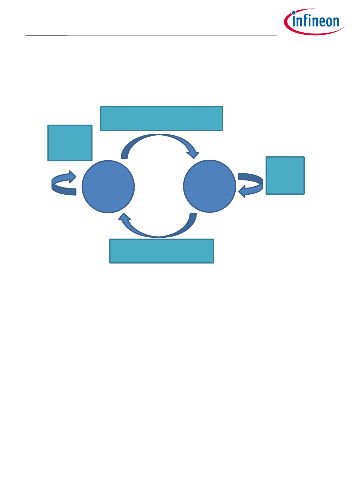
6 Macro and micro threshold tuning
In the presence detection solution, there is a macro and micro mode concept. The macro then micro detection
mode can be illustrated using a state machine.
Figure 9 Presence detect state diagram
When the detection is in absence state, it will check the macro level. If the macro level is higher than the macro
threshold, the macro trigger confirmation count will increase by 1. If the confirmation count exceeds the macro
trigger delay, the state will transit from absence to presence. For presence state, the state remains in presence
when the micro level is higher than the micro threshold. When the micro level is lower than the micro
threshold, the absence count will increase by 1. If the absence count exceeds micro valid, the state will return
to absence.
Sensitivity settings (high, medium and low) have pre-defined macro and micro threshold values. If the user
finds the sensitivity is not enough even with high sensitivity, they can manually set the micro and macro
threshold value to fit their use case.
6.1 Reading the macro and micro level
The following steps are used to enable macro- and micro-level tuning.
1. Turn “Calibration mode” to “On”.
2. Set “Detection mode” to “macro and micro”.
3. Set “Calibration rate” to 4, so the solution will report the update rate as fast as possible.
With these settings, the presence detection solution would report the macro- and micro-level readings. An
example is shown below (macro level 1.155, micro level 219.1):
Absence Presence
Macro level > Macro threshold
Confirmation count > Macro trigger delay
Micro
level >
Micro
threshold
Macro level
< Macro
threshold
Micro level < Micro threshold
Absence count > Micro valid

13 of 20
2022-05-16
XENSIV™60GHz BGT60TR13C Radar System on Module MCU4
Presence Detection
Macro and micro threshold tuning
macro 1.155223 at 0.33, micro 219.102509 at 0.33
6.2 Increase sensitivity by parameter adjustment
To increase the sensitivity further, the user must:
1. Find out the noise floor value of the system
2. Set the threshold above the noise floor
To find out the noise floor value, the user must empty the detection area so no one is inside. Put the radar
module into a product casing so it will have a temperature similar to the product environment, as temperature
can affect the noise floor. Record the macro and micro level for a period of time, and take the maximum
reading as macro and micro noise level. The threshold level can then be set to 15 to 20 percent above noise
level.

14 of 20
2022-05-16
XENSIV™60GHz BGT60TR13C Radar System on Module MCU4
Presence Detection
Signal verification mode
7 Signal verification mode
The radar SoM provides a feature called signal verification mode to check the RF attenuation due to the plastic
material. Signal verification mode is a feature to output range bin profile. For a basic explanation of how FMCW
radar measures distance, see the following link.
https://www.infineon.com/dgdl/Infineon-Radar%20FAQ-PI-v02_00-
EN.pdf?fileId=5546d46266f85d6301671c76d2a00614
The range bin profile is an array of floating numbers showing the received signal level (in dB) at different
distances. An example of a range bin profile is shown below. This feature can be used to measure the RF
attenuation due to the plastic casing.
Figure 10 Range bin profile

15 of 20
2022-05-16
XENSIV™60GHz BGT60TR13C Radar System on Module MCU4
Presence Detection
Signal verification mode
7.1 Measurement setup
Put the radar in an open area, to minimize the reflected signal due to other static objects. At 1 m distance, place
a corner reflector to maximize the reflected signal at 1 m. The user can then look at the signal level at 1 m to
compare the difference with and without plastic casing. If the difference is smaller than 2 dB, it can be
considered a good plastic casing that does not attenuate the RF signal too much.
Figure 11 Measurement setup
Recommended corner reflector size (a: 50 mm; L: 70 mm).
Figure 12 Corner reflector

16 of 20
2022-05-16
XENSIV™60GHz BGT60TR13C Radar System on Module MCU4
Presence Detection
Anti
-
interfer
ence
8Anti-interference
When an environment is using more than one radar module for presence detection, interference may occur and
result in a false alarm. The radar module may report a presence event even inside a detection zone. To avoid
this issue, the user can set the chirps-per-frame parameter to a higher value (e.g., 16) to enable the radar to
check whether interference has occurred or not.
When using the 16 chirps-per-frame setting, the radar can filter out interference with up to 20 radar modules
operating at the same time.

17 of 20
2022-05-16
XENSIV™60GHz BGT60TR13C Radar System on Module MCU4
Presence Detection
Firmware update
9Firmware update
A firmware update can be done under the “Firmware update” tab. Select the target .bin file by pressing the
“Select” button. Bootloader mode will be entered automatically during the update process. In case non-
working firmware is loaded, the user can manually force the module to enter bootloader mode by pressing the
user button on the motherboard after power-up or reset. The LED will change to blue when bootloader mode is
entered.
Figure 13 Firmware update tab page
Press the “Flash” button to start the firmware update. The whole update process should take around 20 s.
Although a protection mechanism is included in the update process, it is recommended not to unplug the USB
or power off the board to prevent any unexpected errors.
Figure 14 Firmware update in process

18 of 20
2022-05-16
XENSIV™60GHz BGT60TR13C Radar System on Module MCU4
Presence Detection
Additional documents
10 Additional documents
Specific user guides are available, including the following:
Infineon XENSIV™60GHz BGT60TR13C SoM solution for presence detection user guide: Board
specification, GPIO indication for presence event detection, hardware description and start-up,
schematics and layout.
Infineon XENSIV™60GHz BGT60TR13C SoM MCU4 binary command protocol manual: Describes the
binary command protocol for integration of the module with a serial connection.

19 of 20
2022-05-16
XENSIV™60GHz BGT60TR13C Radar System on Module MCU4
Presence Detection
Table of contents
Revision history
Document
version
Date of release Description of changes
06/02/2020 1.0 Engineering samples release version
21/04/2020 1.1 Productive release version (updated introduction and firmware update
contents)
19/06/2020 1.2 Maintenance release version (updated configuration table content)
30/09/2020 1.3 Maintenance release version (updated configuration table content)
15/01/2021 1.4 Updated hardware description and signal verification mode
18/02/2021 1.5 Updated threshold tuning method
31/05/2021 1.6 Added chapter for anti-interference
13/07/2021 1.7 Updated sensitivity description

Published by
Infineon Technologies AG
81726 Munich, Germany
© 2022 Infineon Technologies AG.
All Rights Reserved.
Do you have a question about this
document?
Email: [email protected]om
Document reference
Important notice
The information contained in this application note
is given as a hint for the implementation of the
product only and shall in no event be regarded as a
description or warranty of a certain functionality,
condition or quality of the product. Before
implementation of the product, the recipient of this
application note must verify any function and other
technical information given herein in the real
application. Infineon Technologies hereby
disclaims any and all warranties and liabilities of
any kind (including without limitation warranties of
non-infringement of intellectual property rights of
any third party) with respect to any and all
information given in this application note.
The data contained in this document is exclusively
intended for technically trained staff. It is the
responsibility of customer’s technical departments
to evaluate the suitability of the product for the
intended application and the completeness of the
product information given in this document with
respect to such application.
Warnings
Due to technical requirements products may
contain dangerous substances. For information on
the types in question please contact your nearest
Infineon Technologies office.
Except as otherwise explicitly approved by Infineon
Technologies in a written document signed by
authorized representatives of Infineon
Technologies, Infineon Technologies’ products may
not be used in any applications where a failure of
the product or any consequences of the use thereof
can reasonably be expected to result in personal
injury.
Trademarks
All referenced product or service names and trademarks are the property of their respective owners.
UM_2205_PL38_2205_132408
Other manuals for XENSIV BGT60TR13C
1
Table of contents
Other Infineon Radar manuals


Popular Radar manuals by other brands

Garmin
Garmin GMR 400 installation instructions

Hesai
Hesai QT128C2X user manual

Carmanah
Carmanah G Series Cabinet Door Replacement Guide

Magnetrol
Magnetrol Pulsar Foundation fieldbus R96 operating manual

Endress+Hauser
Endress+Hauser Micropilot FWR30 operating instructions

IDS GeoRadar
IDS GeoRadar RockSpot user guide


